EP2177973A2 - Berührungsbildschirmanzeigevorrichtung zur Ausführung eines Flash-Modus und Verfahren für Betrieb der Vorrichtung - Google Patents
Berührungsbildschirmanzeigevorrichtung zur Ausführung eines Flash-Modus und Verfahren für Betrieb der Vorrichtung Download PDFInfo
- Publication number
- EP2177973A2 EP2177973A2 EP09252433A EP09252433A EP2177973A2 EP 2177973 A2 EP2177973 A2 EP 2177973A2 EP 09252433 A EP09252433 A EP 09252433A EP 09252433 A EP09252433 A EP 09252433A EP 2177973 A2 EP2177973 A2 EP 2177973A2
- Authority
- EP
- European Patent Office
- Prior art keywords
- touch
- brightness
- illuminance
- light
- light emission
- Prior art date
- Legal status (The legal status is an assumption and is not a legal conclusion. Google has not performed a legal analysis and makes no representation as to the accuracy of the status listed.)
- Ceased
Links
Images


Classifications
-
- G—PHYSICS
- G06—COMPUTING OR CALCULATING; COUNTING
- G06F—ELECTRIC DIGITAL DATA PROCESSING
- G06F3/00—Input arrangements for transferring data to be processed into a form capable of being handled by the computer; Output arrangements for transferring data from processing unit to output unit, e.g. interface arrangements
- G06F3/01—Input arrangements or combined input and output arrangements for interaction between user and computer
- G06F3/03—Arrangements for converting the position or the displacement of a member into a coded form
- G06F3/041—Digitisers, e.g. for touch screens or touch pads, characterised by the transducing means
- G06F3/0416—Control or interface arrangements specially adapted for digitisers
-
- G—PHYSICS
- G06—COMPUTING OR CALCULATING; COUNTING
- G06F—ELECTRIC DIGITAL DATA PROCESSING
- G06F3/00—Input arrangements for transferring data to be processed into a form capable of being handled by the computer; Output arrangements for transferring data from processing unit to output unit, e.g. interface arrangements
- G06F3/01—Input arrangements or combined input and output arrangements for interaction between user and computer
- G06F3/03—Arrangements for converting the position or the displacement of a member into a coded form
- G06F3/041—Digitisers, e.g. for touch screens or touch pads, characterised by the transducing means
- G06F3/042—Digitisers, e.g. for touch screens or touch pads, characterised by the transducing means by opto-electronic means
-
- G—PHYSICS
- G06—COMPUTING OR CALCULATING; COUNTING
- G06F—ELECTRIC DIGITAL DATA PROCESSING
- G06F3/00—Input arrangements for transferring data to be processed into a form capable of being handled by the computer; Output arrangements for transferring data from processing unit to output unit, e.g. interface arrangements
- G06F3/01—Input arrangements or combined input and output arrangements for interaction between user and computer
- G06F3/03—Arrangements for converting the position or the displacement of a member into a coded form
- G06F3/033—Pointing devices displaced or positioned by the user, e.g. mice, trackballs, pens or joysticks; Accessories therefor
- G06F3/0354—Pointing devices displaced or positioned by the user, e.g. mice, trackballs, pens or joysticks; Accessories therefor with detection of two-dimensional [2D] relative movements between the device, or an operating part thereof, and a plane or surface, e.g. 2D mice, trackballs, pens or pucks
- G06F3/03547—Touch pads, in which fingers can move on a surface
-
- G—PHYSICS
- G06—COMPUTING OR CALCULATING; COUNTING
- G06F—ELECTRIC DIGITAL DATA PROCESSING
- G06F3/00—Input arrangements for transferring data to be processed into a form capable of being handled by the computer; Output arrangements for transferring data from processing unit to output unit, e.g. interface arrangements
- G06F3/01—Input arrangements or combined input and output arrangements for interaction between user and computer
- G06F3/03—Arrangements for converting the position or the displacement of a member into a coded form
- G06F3/041—Digitisers, e.g. for touch screens or touch pads, characterised by the transducing means
- G06F3/0412—Digitisers structurally integrated in a display
-
- G—PHYSICS
- G06—COMPUTING OR CALCULATING; COUNTING
- G06F—ELECTRIC DIGITAL DATA PROCESSING
- G06F3/00—Input arrangements for transferring data to be processed into a form capable of being handled by the computer; Output arrangements for transferring data from processing unit to output unit, e.g. interface arrangements
- G06F3/01—Input arrangements or combined input and output arrangements for interaction between user and computer
- G06F3/03—Arrangements for converting the position or the displacement of a member into a coded form
- G06F3/041—Digitisers, e.g. for touch screens or touch pads, characterised by the transducing means
- G06F3/0416—Control or interface arrangements specially adapted for digitisers
- G06F3/04166—Details of scanning methods, e.g. sampling time, grouping of sub areas or time sharing with display driving
-
- H—ELECTRICITY
- H10—SEMICONDUCTOR DEVICES; ELECTRIC SOLID-STATE DEVICES NOT OTHERWISE PROVIDED FOR
- H10K—ORGANIC ELECTRIC SOLID-STATE DEVICES
- H10K50/00—Organic light-emitting devices
Definitions
- the present invention relates to a touch screen display apparatus which easily recognizes a touch position by using an optical sensor and a method of operating the apparatus.
- a touch screen display apparatus in which an optical sensor is integrated with a panel, inputs information by detecting a finger image that is projected on a screen or by detecting light that is irradiated from a light emitting object such as a light pen.
- a touch screen display apparatus may derive a touch position by using external light or by using internal light emitted by the touch screen display apparatus itself.
- a sensing operation may not be performed by an optical sensor.
- the intensities of the external light and the internal light are similar to each other, an image of a touch object is not formed, and thus, the optical sensor may not perform a sensing operation.
- a touch position may not be recognized, thus limiting the effectiveness of the touch screen display apparatus.
- aspects of embodiments of the present invention are directed toward a touch screen display apparatus which effectively recognizes a touch position by utilizing an optical sensor, and a method of operating the apparatus.
- a touch screen display apparatus including: a panel including a light emitting device for displaying a display image and an optical sensor for generating a touch object image; a touch sensing unit on the panel for sensing a touch of a touch object; and a light emission controller for controlling the light emitting device to emit light when a touch of the touch object is sensed by the touch sensing unit.
- the light emission controller may include: a touch measuring portion for measuring a touch sensing signal corresponding to the touch of the touch object; a touch determining portion for determining whether a touch is performed by comparing the touch sensing signal with a reference signal; and a light emission signal generator for generating a light emission signal when a touch of the touch object is performed in accordance with a result of the determination of the touch determining portion.
- the apparatus may further include a position deriving portion for deriving a touch position from the touch object image.
- the apparatus may further include a flash mode controller for controlling operations of the touch sensing unit and the light emission controller.
- the apparatus may further include an illuminance sensing unit for sensing an external illuminance; and an illuminance determining portion for comparing the external illuminance with a reference illuminance.
- the flash mode controller may be configured to operate the touch sensing unit and the light emission controller.
- the apparatus may further include: a brightness deriving portion for deriving a brightness of the display image; and a brightness determining portion for comparing the brightness of the display image with a reference brightness.
- the flash mode controller may be configured to operate the touch sensing unit and the light emission controller.
- the apparatus may further include: an illuminance deriving portion for deriving an external illuminance from the optical sensor; and an illuminance determining portion for comparing the external illuminance with a reference illuminance.
- the flash mode controller may be configured to operate the touch sensing unit and the light emission controller.
- the apparatus may further include: a brightness deriving portion for deriving a brightness of the display image; and a brightness determining portion for comparing the brightness with a reference brightness, wherein when the brightness is less than the reference brightness, the flash mode controller may be configured to operate the touch sensing unit and the light emission controller.
- the apparatus may further include a position deriving portion for deriving a touch position from the touch object image, wherein when the touch position is not derived by the position deriving portion, the flash mode controller may be configured to operate the touch sensing unit and the light emission controller.
- the position deriving portion may include an image obtaining portion for obtaining the touch object image and a position calculating portion for determining a touch position by analyzing the touch object image, and wherein the touch position may be not derived by the position deriving portion when the touch object image is not obtained by the image obtaining portion or when the touch position is not determined by the position calculating portion.
- a method of driving a touch screen display apparatus including a light emitting device for displaying a display image and an optical sensor for generating a touch object image, the method including: sensing a touch of a touch object and generating a sensing signal; generating a light emission signal corresponding to the sensing signal; and emitting light in accordance with the light emission signal, wherein the emitting of the light is performed by the light emitting device.
- the method may further include comparing the sensing signal with a reference signal, wherein when the sensing signal is greater than the reference signal, the light emission signal may be generated.
- the method may further include: obtaining the touch object image from emission of the light emitting device; and deriving the touch position from the touch object image.
- the method may further include: sensing an external illuminance; comparing the external illuminance with a reference illuminance, and generating the sensing signal and the light emission signal when the external illuminance is less than the reference illuminance.
- the method may further include: deriving brightness of the display image; comparing the brightness with a reference brightness, and generating the sensing signal and the light emission signal when the brightness is less than the reference brightness.
- the external illuminance may be measured by the optical sensor.
- the sensing signal and the light emission signal may be generated.
- FIG. 1 schematically illustrates a touch screen display apparatus according to an embodiment of the present invention
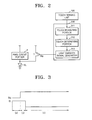
- FIG. 2 schematically illustrates components for performing a flash mode in the touch screen display apparatus of FIG. 1 ;
- FIG. 3 is a timing diagram of an organic electroluminescent (EL) device and a switching element of the touch screen display apparatus of FIG. 2 ;
- EL organic electroluminescent
- FIG. 4 is a flowchart illustrating a method of driving the touch screen display apparatus of FIG. 1 , according to an embodiment of the present invention
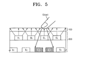
- FIG. 5 is a schematic cross-sectional view explaining driving of the touch screen display apparatus of FIG. 1 ;
- FIG. 6 schematically illustrates a touch screen display apparatus for performing a flash mode when the intensities of external light and internal light are low, according to another embodiment of the present invention
- FIG. 7 is a flowchart illustrating a method of driving the touch screen display apparatus of FIG. 6 , according to another embodiment of the present invention.
- FIG. 8 is a flowchart illustrating a method of driving the touch screen display apparatus of FIG. 6 , according to another embodiment of the present invention.
- FIG. 9 schematically illustrates a touch screen display apparatus for performing a flash mode when the intensities of external light and internal light are low, according to another embodiment of the present invention.
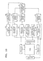
- FIG. 10 schematically illustrates a touch screen display apparatus for performing a flash mode when the intensities of external light and internal light are similar to each other, according to another embodiment of the present invention
- FIG. 11 schematically illustrates a case when the intensities of external light and internal light are similar to each other in the touch screen display apparatus of FIG. 10 ;
- FIG. 12 is a flowchart illustrating a method of driving a touch screen display apparatus for performing a flash mode when the intensities of external light and internal light are similar to each other, according to another embodiment of the present invention
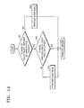
- FIG. 13 schematically illustrates a touch screen display apparatus for performing a flash mode when a touch position is not searched for, according to an embodiment of the present invention.
- FIG. 14 is a flowchart illustrating a method of driving a touch screen display apparatus for performing a flash mode when a touch position is not searched for, according to another embodiment of the present invention.
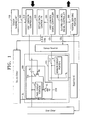
- FIG. 1 schematically illustrates a touch screen display apparatus according to an embodiment of the present invention.
- the touch screen display apparatus includes a touch sensing unit 100, an organic light emitting display panel 200, a plurality of drivers which drive the organic light emitting display panel 200, and a controller 300.
- the touch sensing unit 100 is a touch panel which senses a touch by utilizing either an electrostatic capacity method, a pressure reducing method, or a resistive membrane method.
- the touch sensing unit 100 is disposed in front of the organic light emitting display panel 200 and may sense whether an object touches the touch panel. Since the touch sensing unit 100 is disposed in front of the organic light emitting display panel 200, the touch sensing unit 100 may be formed of a transparent material having very good (or high) light transmittance.
- the organic light emitting display panel 200 includes a display unit 210 and an optical sensor unit 220, which may be formed together.
- the display unit 210 includes a first scan line SL 1 and a data line DL, which are disposed to cross each other, a pixel circuit portion P, which is connected to the first scan line SL 1 and the data line DL, and an organic electroluminescent (EL) device, which emits light corresponding to a current or voltage supplied by the pixel circuit portion P.
- the EL device is, for example, a light emitting device.
- the organic light emitting display panel 200 includes the first scan line SL 1 , the data line DL, the pixel circuit portion P that is connected between the first scan line SL 1 and the data line DL, and the organic EL device.
- the organic light emitting display panel 200 may include a plurality of first scan lines SL 1 that are arranged in parallel, a plurality of data lines DL that are arranged in parallel, a plurality of pixel circuit portions P that are connected between the plurality of first scan lines SL 1 and the plurality of data lines DL, and a plurality of organic ELs that are respectively connected to the plurality of pixel circuit portions P.
- the plurality of first scan lines SL 1 allow the plurality of pixel circuit portions P to operate in response to a first control signal CS 1 supplied by the first control signal controller 330 to the scan driver.
- Display data is applied to the plurality of data lines DL from a source driver in synchronization with the first control signal CS 1 .
- a current or voltage corresponding to the display data is generated by each of the pixel circuit portions P and is output to the plurality of organic ELs to emit light so that the organic light emitting display panel 200 can display an image (e.g., a predetermined image).
- the display unit 210 includes a switching element T which controls the emission of the plurality of organic ELs so as to perform a flash mode.
- the switching element T may supply a set (or predetermined) current or voltage corresponding to a driving voltage VDD to the plurality of organic ELs for the plurality of organic ELs to emit light.
- the flash mode will be described later in greater detail.
- the optical sensor unit 220 includes a plurality of second scan lines SL 2 and a plurality of output lines RL, and a sensor circuit portion S, which is connected between the plurality of second scan lines SL 2 and the plurality of output lines RL.
- the sensor circuit portion S may include an optical sensor and an amplification circuit that amplifies signals sensed by the optical sensor.
- the optical sensor may be a PIN type optical diode.
- the optical sensor unit 220 calculates a coordinate of a touch position by interpreting a finger image due to external light or internal light when the optical sensor unit 220 senses that an object such as a user's finger has touched a touch panel of the touch sensing unit 100, or when the optical sensor unit 220 forms an image by interpreting an amount of light, and correspondingly calculates a position coordinate of the touch position.
- the plurality of second scan lines SL 2 transmit a second control signal CS 2 , which operates the sensor circuit portion S and is supplied by a sensor scanner.
- the plurality of output lines RL output signals that are sensed by the sensor circuit portion S to a read out integrated circuit (ROIC). Then, the signals are transmitted from the ROIC to the controller 300 in which the touch position is calculated.
- ROIC read out integrated circuit
- the touch screen display apparatus further includes the controller 300.
- the controller 300 may include a light emission controller 310, a display data controller 320, a first control signal controller 330, a second control signal controller 340, and a position deriving portion 350.
- the light emission controller 310 outputs a light emission signal Sig that operates the switching element T of the organic light emitting display panel 200, due to a touch sensing signal transmitted by the touch sensing unit 100, and the plurality of organic ELs emit light due to the light emission signal Sig.
- a touch is sensed by the touch sensing unit 100, and the switching element T operates in synchronization with the sensed touch.
- a current or voltage corresponding to a driving voltage VDD is supplied by a VDD source that is connected to a terminal of the switching element T so that the plurality of organic ELs emit light.
- the internal light is forcibly generated so that the optical sensor unit 220 can perform a sensing operation.
- the light emission controller 310 includes a touch measuring portion 311, a touch determining portion 312, and a light emission signal generator 313.
- the touch measuring portion 311 measures the touch sensing signal that is supplied by the touch sensing unit 100.
- the touch sensing unit 100 utilizing an electrostatic capacity method, may sense a change of electrostatic capacity due to a touch of a conductive object, and the touch measuring portion 311 may measure the amount of change of electrostatic capacity.
- the touch determining portion 312 may determine whether the amount of change of electrostatic capacity is equal to or greater than a reference amount (e.g., a predetermined reference amount). In other words, the touch determining portion 312 determines whether a touch of the object is performed by utilizing the touch sensing unit 100.
- a reference amount e.g., a predetermined reference amount
- the light emission signal generator 313 when it is determined that the amount of change of electrostatic capacity is equal to or greater than the reference amount, the light emission signal generator 313 generates the light emission signal Sig to operate the switching element T of the organic light emitting display panel 200 so that the plurality of organic ELs emit light.
- the light emission signal Sig that is applied to the switching element T and an operating signal of the plurality of organic ELs may be illustrated by a timing diagram of FIG. 3 .
- a touch is sensed by the touch sensing unit 100 during a period (a), and the light emission controller 310 generates the light emission signal Sig at a low level.
- the plurality of organic ELs emit light for the period (a).
- the light emission controller 310 generates the light emission signal Sig at a high level during a period (b) so that the emission of light by the plurality of organic ELs is stopped.
- a touch position may be determined and input information corresponding to the touch position may be determined.
- the plurality of organic ELs emit light due to a light emission signal em at a low level that is generated during a period (c) based on display data.
- the display data is based on the input information.
- the emission of light by the plurality of organic ELs is not to display an image but is for the optical sensor unit 220 to effectively perform a sensing operation.
- the light emission signal Sig is generated so that the plurality of organic ELs emit light for an amount of time (e.g., a predetermined amount of time).
- the plurality of organic ELs may emit light during a period in which the optical sensor unit 220 generates the amount of light required for the optical sensor unit 220.
- the display data controller 320 and the first control signal controller 330 output signals that are used to control the touch screen display apparatus so that a plurality of pixels emit light and an image is displayed.
- the display data controller 320 transmits display data, i.e., red (R), green (G), and blue (B) data to the source driver.
- the source driver transmits signals corresponding to the display data (R, G, B data) to the plurality of data lines DL.
- the first control signal controller 330 transmits the first control signal CS 1 to the scan driver.
- the scan driver sequentially transmits scan signals to the plurality of first scan lines SL 1 in response to the first control signal CS 1 .
- the second control signal controller 340 and the position deriving portion 350 are controllers related to the optical sensor unit 220.
- the second control signal controller 340 transmits the second control signal CS 2 to the sensor scanner.
- the sensor scanner sequentially applies scan signals to the plurality of second scan lines SL 2 in response to the second control signal CS 2 .
- the position deriving portion 350 calculates a touch position by utilizing a signal that is sensed by the optical sensor unit 220 and is input to the position deriving portion 350 via the ROIC.
- a method of driving the touch screen display apparatus having the above structure, according to an embodiment of the present invention, will now be described with reference to FIG. 4 .
- a flash mode is performed.
- the touch sensing unit 100 determines whether a touch of an object is sensed. When it is determined in operation S12 that a touch is not sensed, the touch sensing unit 100 again determines whether a touch of an object is sensed. That is, operation S12 is re-performed.
- an amount of change of touch information due to the touch is measured.
- the amount of change of capacitance, the amount of change of permittivity, the amount of change of a gap, etc. may be measured, and in the case of utilizing the resistive layer method, the amount of change of resistance, etc., may be measured.
- operation S14 it is determined whether the amount of change of information is equal to or greater than a reference amount, where the reference amount may be determined in advance from, for example, prior test results.
- the touch sensing unit 100 returns to operation S12 to determine whether a touch of an object is sensed.
- a light emission signal is generated in operation S15 to operate the switching element T that controls emission of the plurality of organic ELs.
- the plurality of organic ELs emit light.
- the plurality of organic ELs typically emit light so that a display image may be displayed based on display data. However in operation S16, the plurality of organic ELs instead emit light based on the touch information that is obtained by the touch sensing unit 100.
- the plurality of organic ELs emit light based on the touch information.
- an image of the touch object is obtained by utilizing optical sensors by utilizing emission of the plurality of organic ELs. Then, in operation S18, the image of the touch object is analyzed and the touch position is derived.
- the touch sensing unit 100 is disposed on the organic light emitting display panel 200, and the plurality of organic ELs are disposed on an upper portion of the organic light emitting display panel 200, and first through fifth optical sensors S 1 to S 5 are integrated between the plurality of organic ELs.
- the plurality of organic ELs emit light.
- the plurality of organic ELs when an intensity of external light is low and/or when the amount of light utilized to display an image (i.e., when an intensity of internal light) is low, the plurality of organic ELs forcibly emit light.
- the internal light that is emitted by the plurality of organic ELs is reflected by the object, and the reflected light is received by the third optical sensor S 3 and the fourth optical sensor S 4 so that the touch object can be imaged.
- the image of the touch object may be black and white.
- the image of the touch object may be analyzed and the touch position may be recognized.
- touch screen display apparatuses and methods of driving the same according to embodiments of the present invention will be described in more detail.
- FIGS. 6 through 9 illustrate a touch screen display apparatus for performing a flash mode when intensities of external light and internal light are low, according to another embodiment of the present invention.
- like reference numerals and like names are the same as those of FIG. 1 , etc. and thus, a detailed description thereof will not be provided again.
- a touch screen display apparatus and a method of driving the same when the intensities of external light and internal light are low, according to embodiments of the present invention, will now be described with reference to FIGS. 6 and 7 .
- the touch screen display apparatus of FIG. 6 further includes an illuminance sensing portion 361.
- the flash mode is controlled based on illuminance sensed by the illuminance sensing portion 361.
- the touch screen display apparatus includes the touch sensing unit 100, the organic light emitting display panel 200 including a display unit for displaying an image and an optical sensor unit for generating an image of a touch object, the source driver that drives the display unit of the organic light emitting display panel 200, the scan driver, the sensor scanner that drives the optical sensor unit of the organic light emitting display panel 200, and the read out integrated circuit (ROIC).
- the touch sensing unit 100 the organic light emitting display panel 200 including a display unit for displaying an image and an optical sensor unit for generating an image of a touch object
- the source driver that drives the display unit of the organic light emitting display panel 200
- the scan driver the sensor scanner that drives the optical sensor unit of the organic light emitting display panel 200
- ROIC read out integrated circuit
- the illuminance sensing portion 361 senses the amount of external light, i.e., illuminance.
- operation S22 it is determined whether the illuminance sensed by an illuminance determining portion 363 is equal to or greater than a reference illuminance.
- the optical sensor may perform the sensing operation by using external light.
- the image of the touch object is obtained so that the touch position may be determined.
- a brightness of display data is derived.
- the display data may be derived from the display data controller 320 by using a brightness deriving portion 371.
- the display data is utilized to implement a current image included in a user interface (UI) and may be utilized to determine the amount of light emitted by the organic light emitting display panel 200, i.e., the amount of internal light from the brightness of the displayed image.
- UI user interface
- a brightness determining portion 373 determines whether the brightness (e.g., of internal light) is equal to or greater than a reference brightness.
- the sensing operation may be performed by the optical sensor by utilizing internal light emitted by the plurality of organic ELs from to the display data.
- the process proceeds to operation S27, where flash mode is performed. That is, the information is transmitted to a flash mode controller 380, and the touch sensing unit 100 and the light emission controller 310 operate based on the information.
- the touch sensing unit 100 senses whether the touch of the object is sensed, information about the case when the touch of the object is sensed is transmitted to the light emission controller 310, and the light emission controller 310 controls the organic light emitting display panel 200 so that the organic light emitting display panel 200 emits light for a time based on when the touch of the object is sensed.
- the plurality of organic ELs emit light. Due to the emission of light by the plurality of organic ELs, an image of the touch object is obtained by the optical sensor, such that the image may be analyzed and the touch position may be determined.
- a method of driving the touch screen display apparatus of FIG. 6 will now be described with reference to FIG. 8 .
- a UI e.g., a predetermined UI
- the UI may be a button or a bright dot or dark dot, for example.
- the UI is used as an input unit.
- operation S34 it is determined whether a brightness level of the display data of a current image may be increased so that a brighter image can be displayed. In addition, it is determined whether the brightness level of the display data may be increased such that a sufficient amount of light sensed by the optical sensor can be generated, and whether a brighter image may be displayed.
- the brightness level of the display data is increased.
- the touch object may be imaged utilizing the optical sensor by utilizing the image that is implemented utilizing the display data having the increased brightness level as internal light. Thus, the touch position of the object may be determined.
- the flash mode is performed.
- the touch sensing unit 100 senses the touch of the object, and the plurality of organic ELs that are disposed in the organic light emitting display panel 200 forcibly emit light based on the touch sensing information so that the touch position can be determined by utilizing the internal light due to emission of light by the plurality of organic ELs.
- FIG. 9 illustrates a touch screen display apparatus for performing a flash mode when the intensities of internal light and external light are low, according to another embodiment of the present invention.
- FIG. 9 illustrates a touch screen display apparatus that senses illuminance by utilizing the optical sensor of the organic light emitting display panel 200 without an illuminance sensing portion 361.
- the optical sensor disposed on the organic light emitting display panel 200 senses the external light, and a sensing signal of the external light sensed by the optical sensor is read from the ROIC. Then, the ROIC transmits the sensing signal to an illuminance deriving portion 362.
- the illuminance deriving portion 362 derives the illuminance from the sensing signal, and the illuminance determining portion 363 determines whether the illuminance is equal to or greater than a reference illuminance.
- the illuminance determination, brightness deriving, and brightness determination of the touch screen display apparatus of FIG. 9 are performed similarly as described with respect to FIG.
- the touch screen display apparatus of FIG. 9 may use either the method of driving the touch screen display apparatus of FIG. 7 or FIG. 8 .
- Touch screen display apparatuses performing a flash mode when the intensities of external light and internal light are similar to each to other and methods of driving the same according to embodiments of the present invention will now be described with reference to FIGS. 10 through 12 .
- the touch screen display apparatus includes an illuminance sensing portion 361, a brightness deriving portion 371, and a comparing and determining portion 375 that compares and determines illuminance and brightness provided by the illuminance sensing portion 361 and the brightness deriving portion 371, respectively.
- an image of a touch object may not be generated by an optical sensor and thus, the touch object image may not be obtained.
- external light a is input to a portion of the first, second, and fifth optical sensors S 1 , S 2 , and S 5
- reflected light of internal light b is input to the third and fourth optical sensors S 3 and S 4 .
- an image of the touch object may not be formed.
- the amounts of reflected light of the external light a and the internal light b are similar to each other (e.g., when the amounts of reflected light of the external light a and the internal light b are substantially the same), the above case may occur.
- the plurality of organic ELs may forcibly emit light so that the amounts of reflected light of the internal light b are increased and the touch position may be determined.
- the emission of light of the plurality of organic ELs may be forcibly and temporarily prevented so that the touch position can be determined by using the external light a.
- the comparing and determining portion 375 determines whether the illuminance and the brightness are similar to each other, to determine whether the amount of the external light a and the amount of the internal light b or the amounts of the reflected light of the internal light b are similar to each other. Also, similarity settings may be pre-set based on previous experience.
- the touch screen display apparatus may further include an illuminance deriving portion 362.
- the illuminance deriving portion 362 may derive illuminance from the ROIC, and the brightness deriving portion 371 may derive brightness, and the comparing and determining portion 375 may compare and determine the illuminance and the brightness.
- operation S41 illuminance is sensed, and in operation S42, the brightness is derived from the display data.
- the sequence of performing the operation of the sensing of the illuminance (S41) and the operation of the deriving of the brightness (S42) may be interchangeable.
- operation S43 it is determined whether the illuminance and the brightness are similar to each other.
- the external light and the internal light may fall within a range (e.g., a predetermined range) where an image of the touch object may not be formed.
- operation S44 When it is determined in operation S43 that the illuminance and the brightness are similar to each other, in operation S44, the flash mode is performed. Otherwise, when it is determined in operation S43 that the illuminance and the brightness are not similar to each other, in operation S45, the image of the touch object is obtained by the optical sensor, and a touch position is determined.
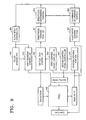
- a touch screen display apparatus for performing a flash mode and a method of driving the same may be used. Such a touch screen display apparatus will now be described with reference to FIGS. 13 and 14 .
- the ROIC may read a signal that is sensed by the optical sensor, and a position deriving portion 350 may determine the touch position based on the signal. More specifically, an image obtaining portion 351 may obtain the image of the touch object based on the signal, and a position calculating portion 353 may calculate and derive the touch position by analyzing the image of the touch object. In this case, when the image obtaining portion 351 may not obtain the image of the touch object or when the position calculating portion 353 may not calculate or derive the touch position, the flash mode controller 380 operates.
- the touch sensing unit 100 senses a touch of an object, and when the touch is sensed by the touch sensing unit 100, the light emission controller 310 controls the organic light emitting display panel 200 to temporarily emit light.
- operation S51 it is determined by an optical sensor whether the image of the touch object is obtained.
- operation S52 When it is determined in operation S51 that the image of the touch object is obtained, in operation S52, the image is analyzed to determine whether the touch position is derived. When it is determined in operation S52 that the touch position is derived, the optical sensor operates based on information about the touch.
- the flash mode is performed.
- the flash mode is performed in operation 54.
- the above embodiments may include determination of at least two items. For example, when it is determined that the illuminance and the brightness are equal to or greater than a reference illuminance and/or a reference brightness, respectively, it may be further determined whether the illuminance and the brightness are similar to each other. When it is further determined that the illuminance and the brightness are similar to each other, a flash mode may be performed. In addition, when it is determined that the illuminance and the brightness are equal to or greater than the reference illuminance and the reference brightness, respectively, the touch position may be determined by the optical sensor. In this case, when the touch position cannot be derived, the flash mode may be performed.
- an organic light emitting display panel may forcibly and temporarily emit light such that a touch position can be determined by the optical sensor.
- the touch screen display apparatus in which the optical sensor is integrated can be more widely used as compared to a general touch screen display apparatus.
- the present invention provides a touch screen display apparatus which enhances reliability by recognizing a touch position by utilizing internal light, even when the touch position cannot be sensed by utilizing external light, and a method of driving the apparatus.
Landscapes
- Engineering & Computer Science (AREA)
- General Engineering & Computer Science (AREA)
- Theoretical Computer Science (AREA)
- Physics & Mathematics (AREA)
- Human Computer Interaction (AREA)
- General Physics & Mathematics (AREA)
- Optics & Photonics (AREA)
- Electroluminescent Light Sources (AREA)
- Control Of Indicators Other Than Cathode Ray Tubes (AREA)
- Position Input By Displaying (AREA)
- Control Of El Displays (AREA)
- Devices For Indicating Variable Information By Combining Individual Elements (AREA)
Applications Claiming Priority (1)
| Application Number | Priority Date | Filing Date | Title |
|---|---|---|---|
| KR20080102106A KR101015883B1 (ko) | 2008-10-17 | 2008-10-17 | 터치 스크린 디스플레이 장치 및 이의 구동 방법 |
Publications (2)
| Publication Number | Publication Date |
|---|---|
| EP2177973A2 true EP2177973A2 (de) | 2010-04-21 |
| EP2177973A3 EP2177973A3 (de) | 2011-11-16 |
Family
ID=41566033
Family Applications (1)
| Application Number | Title | Priority Date | Filing Date |
|---|---|---|---|
| EP20090252433 Ceased EP2177973A3 (de) | 2008-10-17 | 2009-10-16 | Berührungsbildschirmanzeigevorrichtung zur Ausführung eines Flash-Modus und Verfahren für Betrieb der Vorrichtung |
Country Status (6)
| Country | Link |
|---|---|
| US (1) | US9024885B2 (de) |
| EP (1) | EP2177973A3 (de) |
| JP (1) | JP5138657B2 (de) |
| KR (1) | KR101015883B1 (de) |
| CN (1) | CN101727248B (de) |
| TW (1) | TWI443566B (de) |
Cited By (4)
| Publication number | Priority date | Publication date | Assignee | Title |
|---|---|---|---|---|
| CN102314263A (zh) * | 2010-07-08 | 2012-01-11 | 原相科技股份有限公司 | 光学触控屏幕系统、光学距离判断装置及其方法 |
| TWI413927B (zh) * | 2010-10-20 | 2013-11-01 | Pixart Imaging Inc | 視屏顯示模組、顯示裝置及其應用之電子裝置 |
| US9916793B2 (en) | 2012-06-01 | 2018-03-13 | Semiconductor Energy Laboratory Co., Ltd. | Semiconductor device and method of driving the same |
| EP2475010B1 (de) * | 2011-01-10 | 2019-03-27 | Samsung Electronics Co., Ltd. | Organische lichtemittierende Diodenanzeigevorrichtung mit Lichtmessfunktion |
Families Citing this family (13)
| Publication number | Priority date | Publication date | Assignee | Title |
|---|---|---|---|---|
| CA2749607C (en) * | 2009-01-14 | 2018-03-13 | Perceptive Pixel Inc. | Touch-sensitive display |
| US8917262B2 (en) | 2010-01-08 | 2014-12-23 | Integrated Digital Technologies, Inc. | Stylus and touch input system |
| CN102314264B (zh) * | 2010-07-08 | 2013-11-13 | 原相科技股份有限公司 | 光学触控屏幕 |
| KR101407311B1 (ko) * | 2012-10-31 | 2014-06-13 | 엘지디스플레이 주식회사 | 터치표시장치 및 이의 광센서모듈 복구방법 |
| CN103064560B (zh) * | 2013-01-15 | 2016-09-14 | 胡辉 | 一种多点触摸屏 |
| CN103246396B (zh) | 2013-04-18 | 2016-03-30 | 北京京东方光电科技有限公司 | 触控显示电路结构及其驱动方法、阵列基板和显示装置 |
| KR102149984B1 (ko) * | 2013-04-22 | 2020-09-01 | 삼성디스플레이 주식회사 | 표시 장치 및 그 구동 방법 |
| KR101714774B1 (ko) * | 2013-05-29 | 2017-03-09 | 주식회사 디온 | 운송 수단에 구비되는 영상 제어 시스템 |
| CN103411710B (zh) * | 2013-08-12 | 2016-04-06 | 北京纳米能源与系统研究所 | 一种压力传感器、电子皮肤和触屏设备 |
| JP6245357B2 (ja) * | 2014-05-29 | 2017-12-13 | 富士電機株式会社 | 光学的操作入力検出装置、自動販売機、及び光学的操作入力検出方法 |
| KR102530068B1 (ko) * | 2018-06-26 | 2023-05-08 | 삼성전자주식회사 | 발광 소자 패키지, 이를 포함하는 디스플레이 장치, 및 그 제조 방법 |
| KR20240038057A (ko) | 2021-10-18 | 2024-03-22 | 구글 엘엘씨 | 언더-디스플레이 센서를 위한 밝기 제어 |
| WO2025141448A1 (ja) * | 2023-12-28 | 2025-07-03 | 株式会社半導体エネルギー研究所 | 電子機器、及びプログラム |
Family Cites Families (31)
| Publication number | Priority date | Publication date | Assignee | Title |
|---|---|---|---|---|
| SE440386B (sv) | 1980-09-29 | 1985-07-29 | Volvo Ab | Motoranleggning for drift pa framaxeln av ett fordon |
| JPS5933076Y2 (ja) * | 1980-12-10 | 1984-09-14 | 松下電器産業株式会社 | ライトペン入力装置 |
| JPS59161727A (ja) | 1983-03-07 | 1984-09-12 | Hitachi Ltd | コンピユ−タのライトペンシステム |
| JPS62257517A (ja) | 1986-05-01 | 1987-11-10 | Oki Electric Ind Co Ltd | 情報入力装置 |
| JPH09237158A (ja) | 1996-03-01 | 1997-09-09 | Nec Corp | タッチパネル装置 |
| JP2001005613A (ja) | 1999-06-25 | 2001-01-12 | Namco Ltd | 位置検出システム、画像生成システム及び情報記憶媒体 |
| JP2002287900A (ja) | 2000-12-12 | 2002-10-04 | Semiconductor Energy Lab Co Ltd | 情報装置 |
| US6747290B2 (en) | 2000-12-12 | 2004-06-08 | Semiconductor Energy Laboratory Co., Ltd. | Information device |
| DE10123633A1 (de) | 2001-05-09 | 2003-02-06 | Ego Elektro Geraetebau Gmbh | Sensorelement |
| US7586479B2 (en) * | 2004-06-10 | 2009-09-08 | Samsung Electronics Co., Ltd. | Display device and driving method thereof |
| WO2006013518A2 (en) | 2004-08-02 | 2006-02-09 | Koninklijke Philips Electronics N.V. | Touch screen with pressure-dependent visual feedback |
| JP2006079589A (ja) | 2004-08-05 | 2006-03-23 | Sanyo Electric Co Ltd | タッチパネル |
| JP4429124B2 (ja) * | 2004-09-13 | 2010-03-10 | 富士通コンポーネント株式会社 | タッチ入力機能付き表示装置 |
| KR101018751B1 (ko) * | 2004-09-24 | 2011-03-04 | 삼성전자주식회사 | 표시 장치 및 그 구동 방법 |
| KR20060035833A (ko) * | 2004-10-20 | 2006-04-27 | 주식회사 팬택 | 플래쉬의 광도 조절을 위한 이동통신 단말기 |
| JP4580738B2 (ja) | 2004-11-22 | 2010-11-17 | オリンパスイメージング株式会社 | 電子機器 |
| US7800594B2 (en) | 2005-02-03 | 2010-09-21 | Toshiba Matsushita Display Technology Co., Ltd. | Display device including function to input information from screen by light |
| JP4645822B2 (ja) * | 2005-04-19 | 2011-03-09 | ソニー株式会社 | 画像表示装置および物体の検出方法 |
| KR101163602B1 (ko) | 2005-08-18 | 2012-07-06 | 엘지디스플레이 주식회사 | 디스플레이 장치 및 그의 구동 방법 |
| JP2007183706A (ja) | 2006-01-04 | 2007-07-19 | Epson Imaging Devices Corp | タッチセンサシステム |
| JP4557228B2 (ja) * | 2006-03-16 | 2010-10-06 | ソニー株式会社 | 電気光学装置および電子機器 |
| JP4891666B2 (ja) | 2006-06-22 | 2012-03-07 | 東芝モバイルディスプレイ株式会社 | 液晶表示装置 |
| JP2008083322A (ja) | 2006-09-27 | 2008-04-10 | Seiko Epson Corp | 入力機能付き表示装置 |
| JP5016896B2 (ja) * | 2006-11-06 | 2012-09-05 | 株式会社ジャパンディスプレイセントラル | 表示装置 |
| KR101282224B1 (ko) * | 2006-11-20 | 2013-07-09 | 엘지디스플레이 주식회사 | 터치용 액정표시장치의 감도 향상 시스템 및 감도 향상방법 |
| US8094129B2 (en) * | 2006-11-27 | 2012-01-10 | Microsoft Corporation | Touch sensing using shadow and reflective modes |
| JP2008241807A (ja) * | 2007-03-26 | 2008-10-09 | Seiko Epson Corp | 液晶装置及び電子機器 |
| CN101627350A (zh) * | 2007-03-26 | 2010-01-13 | 夏普株式会社 | 定位设备和使用它的显示装置 |
| JP2009064074A (ja) * | 2007-09-04 | 2009-03-26 | Mitsubishi Electric Corp | 入力装置 |
| US9665197B2 (en) * | 2008-01-30 | 2017-05-30 | Nokia Technologies Oy | Apparatus and method for enabling user input |
| US20090244026A1 (en) * | 2008-03-27 | 2009-10-01 | Research In Motion Limited | Touch screen display for electronic device and method of determining touch interaction therewith |
-
2008
- 2008-10-17 KR KR20080102106A patent/KR101015883B1/ko not_active Expired - Fee Related
-
2009
- 2009-10-12 US US12/577,573 patent/US9024885B2/en active Active
- 2009-10-14 TW TW98134723A patent/TWI443566B/zh active
- 2009-10-16 EP EP20090252433 patent/EP2177973A3/de not_active Ceased
- 2009-10-16 CN CN200910205673.XA patent/CN101727248B/zh active Active
- 2009-10-19 JP JP2009240346A patent/JP5138657B2/ja active Active
Cited By (5)
| Publication number | Priority date | Publication date | Assignee | Title |
|---|---|---|---|---|
| CN102314263A (zh) * | 2010-07-08 | 2012-01-11 | 原相科技股份有限公司 | 光学触控屏幕系统、光学距离判断装置及其方法 |
| CN102314263B (zh) * | 2010-07-08 | 2014-02-19 | 原相科技股份有限公司 | 光学触控屏幕系统、光学距离判断装置及其方法 |
| TWI413927B (zh) * | 2010-10-20 | 2013-11-01 | Pixart Imaging Inc | 視屏顯示模組、顯示裝置及其應用之電子裝置 |
| EP2475010B1 (de) * | 2011-01-10 | 2019-03-27 | Samsung Electronics Co., Ltd. | Organische lichtemittierende Diodenanzeigevorrichtung mit Lichtmessfunktion |
| US9916793B2 (en) | 2012-06-01 | 2018-03-13 | Semiconductor Energy Laboratory Co., Ltd. | Semiconductor device and method of driving the same |
Also Published As
| Publication number | Publication date |
|---|---|
| CN101727248A (zh) | 2010-06-09 |
| EP2177973A3 (de) | 2011-11-16 |
| JP5138657B2 (ja) | 2013-02-06 |
| TW201017497A (en) | 2010-05-01 |
| KR20100042899A (ko) | 2010-04-27 |
| TWI443566B (zh) | 2014-07-01 |
| US20100097391A1 (en) | 2010-04-22 |
| JP2010097618A (ja) | 2010-04-30 |
| US9024885B2 (en) | 2015-05-05 |
| CN101727248B (zh) | 2014-06-18 |
| KR101015883B1 (ko) | 2011-02-23 |
Similar Documents
| Publication | Publication Date | Title |
|---|---|---|
| US9024885B2 (en) | Touch screen display apparatus for performing flash mode and method of operating the apparatus | |
| TWI442286B (zh) | 觸控式輸入方法及其裝置 | |
| EP2387745B1 (de) | Berührungsempfindliche anzeige | |
| US8610670B2 (en) | Imaging and display apparatus, information input apparatus, object detection medium, and object detection method | |
| US8154535B2 (en) | Display apparatus and position detecting method | |
| TWI393943B (zh) | 顯示器及影像擷取裝置、物件偵測程式及偵測物件之方法 | |
| US8665223B2 (en) | Display device and method providing display contact information based on an amount of received light | |
| US10013079B2 (en) | Display device and touch detection system | |
| WO2018196281A1 (zh) | Oled显示面板以及使用oled显示面板进行指纹识别的方法 | |
| US20100097352A1 (en) | Touch screen display and method of driving the same | |
| US20130257782A1 (en) | Input system | |
| US20100271336A1 (en) | Image pickup device, display-and-image pickup device, and electronic device | |
| KR102380343B1 (ko) | 센싱부를 포함하는 표시장치 및 그를 이용한 센싱방법 | |
| CN101627350A (zh) | 定位设备和使用它的显示装置 | |
| JP2009193482A (ja) | センシング装置、表示装置、電子機器およびセンシング方法 | |
| US20120206416A1 (en) | Interactive Display | |
| KR102469014B1 (ko) | 통합구동회로부, 그를 이용하는 표시장치 및 구동방법 | |
| CN102163103B (zh) | 触控式输入方法及其装置 | |
| KR101494787B1 (ko) | 터치스크린 장치 | |
| KR20190079861A (ko) | 서브픽셀, 구동 회로 및 디스플레이 장치 | |
| KR20190079859A (ko) | 서브픽셀, 구동 회로 및 디스플레이 장치 | |
| JP2008059253A (ja) | 表示撮像装置、物体検出プログラムおよび物体の検出方法 | |
| JP4788755B2 (ja) | 表示撮像装置、物体検出プログラムおよび物体の検出方法 | |
| JP5381469B2 (ja) | 表示装置 | |
| WO2019113824A1 (zh) | 柔性触摸显示装置及触摸补偿方法 |
Legal Events
| Date | Code | Title | Description |
|---|---|---|---|
| PUAI | Public reference made under article 153(3) epc to a published international application that has entered the european phase |
Free format text: ORIGINAL CODE: 0009012 |
|
| 17P | Request for examination filed |
Effective date: 20091029 |
|
| AK | Designated contracting states |
Kind code of ref document: A2 Designated state(s): AT BE BG CH CY CZ DE DK EE ES FI FR GB GR HR HU IE IS IT LI LT LU LV MC MK MT NL NO PL PT RO SE SI SK SM TR |
|
| AX | Request for extension of the european patent |
Extension state: AL BA RS |
|
| PUAL | Search report despatched |
Free format text: ORIGINAL CODE: 0009013 |
|
| AK | Designated contracting states |
Kind code of ref document: A3 Designated state(s): AT BE BG CH CY CZ DE DK EE ES FI FR GB GR HR HU IE IS IT LI LT LU LV MC MK MT NL NO PL PT RO SE SI SK SM TR |
|
| AX | Request for extension of the european patent |
Extension state: AL BA RS |
|
| RIC1 | Information provided on ipc code assigned before grant |
Ipc: G06F 3/041 20060101AFI20111010BHEP Ipc: G06F 3/042 20060101ALI20111010BHEP |
|
| RAP1 | Party data changed (applicant data changed or rights of an application transferred) |
Owner name: SAMSUNG DISPLAY CO., LTD. |
|
| 17Q | First examination report despatched |
Effective date: 20121114 |
|
| RAP1 | Party data changed (applicant data changed or rights of an application transferred) |
Owner name: SAMSUNG DISPLAY CO., LTD. |
|
| STAA | Information on the status of an ep patent application or granted ep patent |
Free format text: STATUS: THE APPLICATION HAS BEEN REFUSED |
|
| 18R | Application refused |
Effective date: 20161116 |