EP2178065A1 - Vorrichtung zum Berechnen eines Flugplans für ein Flugzeug - Google Patents
Vorrichtung zum Berechnen eines Flugplans für ein Flugzeug Download PDFInfo
- Publication number
- EP2178065A1 EP2178065A1 EP09172684A EP09172684A EP2178065A1 EP 2178065 A1 EP2178065 A1 EP 2178065A1 EP 09172684 A EP09172684 A EP 09172684A EP 09172684 A EP09172684 A EP 09172684A EP 2178065 A1 EP2178065 A1 EP 2178065A1
- Authority
- EP
- European Patent Office
- Prior art keywords
- distance
- flight plan
- aircraft
- point
- flight
- Prior art date
- Legal status (The legal status is an assumption and is not a legal conclusion. Google has not performed a legal analysis and makes no representation as to the accuracy of the status listed.)
- Granted
Links
- 238000001514 detection method Methods 0.000 claims abstract description 13
- 238000011156 evaluation Methods 0.000 claims abstract description 9
- 230000000644 propagated effect Effects 0.000 claims description 20
- 238000005259 measurement Methods 0.000 claims description 8
- 238000000926 separation method Methods 0.000 abstract description 9
- 238000011161 development Methods 0.000 abstract description 4
- 230000001105 regulatory effect Effects 0.000 abstract description 2
- 230000000875 corresponding effect Effects 0.000 description 16
- 230000006870 function Effects 0.000 description 14
- 238000000034 method Methods 0.000 description 6
- 230000007423 decrease Effects 0.000 description 5
- 230000000717 retained effect Effects 0.000 description 5
- WBWWGRHZICKQGZ-HZAMXZRMSA-M taurocholate Chemical compound C([C@H]1C[C@H]2O)[C@H](O)CC[C@]1(C)[C@@H]1[C@@H]2[C@@H]2CC[C@H]([C@@H](CCC(=O)NCCS([O-])(=O)=O)C)[C@@]2(C)[C@@H](O)C1 WBWWGRHZICKQGZ-HZAMXZRMSA-M 0.000 description 5
- 230000005540 biological transmission Effects 0.000 description 4
- 230000002093 peripheral effect Effects 0.000 description 4
- 238000005070 sampling Methods 0.000 description 4
- 238000006073 displacement reaction Methods 0.000 description 3
- 239000000446 fuel Substances 0.000 description 3
- 238000012545 processing Methods 0.000 description 3
- 230000004913 activation Effects 0.000 description 2
- 238000013459 approach Methods 0.000 description 2
- 239000003086 colorant Substances 0.000 description 2
- 238000004891 communication Methods 0.000 description 2
- 230000001419 dependent effect Effects 0.000 description 2
- 230000004807 localization Effects 0.000 description 2
- 231100000773 point of departure Toxicity 0.000 description 2
- 230000002123 temporal effect Effects 0.000 description 2
- 101100536354 Drosophila melanogaster tant gene Proteins 0.000 description 1
- 229920000297 Rayon Polymers 0.000 description 1
- 238000004458 analytical method Methods 0.000 description 1
- 230000008859 change Effects 0.000 description 1
- 238000012512 characterization method Methods 0.000 description 1
- 230000000295 complement effect Effects 0.000 description 1
- 238000010276 construction Methods 0.000 description 1
- 230000002596 correlated effect Effects 0.000 description 1
- 230000003247 decreasing effect Effects 0.000 description 1
- 230000000593 degrading effect Effects 0.000 description 1
- 230000003116 impacting effect Effects 0.000 description 1
- 239000003607 modifier Substances 0.000 description 1
- 238000012544 monitoring process Methods 0.000 description 1
- 230000008447 perception Effects 0.000 description 1
- 235000012830 plain croissants Nutrition 0.000 description 1
- 230000002265 prevention Effects 0.000 description 1
- 230000008569 process Effects 0.000 description 1
- 230000002250 progressing effect Effects 0.000 description 1
- 206010037844 rash Diseases 0.000 description 1
- 239000002964 rayon Substances 0.000 description 1
Images


Classifications
-
- G—PHYSICS
- G08—SIGNALLING
- G08G—TRAFFIC CONTROL SYSTEMS
- G08G5/00—Traffic control systems for aircraft
- G08G5/50—Navigation or guidance aids
- G08G5/55—Navigation or guidance aids for a single aircraft
-
- G—PHYSICS
- G08—SIGNALLING
- G08G—TRAFFIC CONTROL SYSTEMS
- G08G5/00—Traffic control systems for aircraft
- G08G5/50—Navigation or guidance aids
- G08G5/59—Navigation or guidance aids in accordance with predefined flight zones, e.g. to avoid prohibited zones
Definitions
- the invention relates to the navigation of an aircraft whose flight plan is subject to flight constraints and, more particularly, the calculation of a flight plan respecting these constraints.
- An aircraft in flight is subject to various constraints affecting its navigation and more particularly impacting its flight plan. These constraints are, for example, obstacles, reliefs, restricted areas, other aircraft. Various systems have been developed to help a crew develop a flight plan that meets some of these flight constraints.
- the functions accessible via an FMS are insufficient to ensure the respect of all the flight constraints. Indeed, the function of creation of a flight plan does not verify the intersection of the proposed trajectory with the elements surrounding the aircraft (relief, zones, other aircraft, ). In addition, the FMS does not have a digital terrain model to perform interference calculations of the predicted trajectory with terrain. An FMS also does not have the ability to detect surrounding aircraft or nearby weather events.
- the TAWS systems decoupled from navigation systems, periodically compare the theoretical trajectory that the aircraft would describe during a resource and compare it to a section of the terrain overflown obtained from an onboard global digital terrain model. on board the calculator.
- THD Traffic Hazard Display
- Class A TAWS which are mandatory for commercial transport aircraft, generally have a simplified cartographic mode at a few hypsometric sections, making it possible to have a representation of the terrain during cruising flight phases.
- the functions performed by an ISS are insufficient to ensure compliance with all flight constraints.
- the resolution of digital terrain models of the order of 15 arc seconds (or less) is too high compared to the operating margins required for the situations envisaged and in fact not certifiable for navigation functions.
- the interfaces do not provide access to navigation data or the performance model to make predictions of vertical profile, flight time, and required fuel consumption.
- the interfaces do not allow to develop a flight plan nor to follow up via the guidance system.
- WUS Wired Uplink System
- this system is responsible for retrieving meteorological data from multiple sources (radar, surveys, predictions, satellites, ...) and providing the means of communication to establish a data link with an aircraft.
- this system is in charge of establishing the link with the ground device, retrieving the data and making them available to the crew (graphically) or other equipment in order to exploit them at flight management or avoidance of potentially dangerous areas.
- a WUS does not have a numerical model of ground allowing to carry out the calculations of interference of the predicted trajectory with the relief nor of the capacity of detection of the surrounding aircraft or the close weather phenomena.
- the interfaces do not provide access to navigation data or the performance model to make predictions of vertical profile, flight time and required fuel consumption.
- the interfaces do not allow to develop a flight plan nor to follow up via the guidance system.
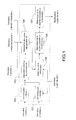
- the invention aims in particular to overcome the problems mentioned above by proposing an onboard device on board an aircraft capable of automatically proposing a revision of the flight plan followed in order to avoid, with sufficient safety margins and over a time horizon of a few minutes, all the fixed obstructions (relief, obstacles, restricted areas) and mobile obstructions (aircraft, weather phenomena) close to the aircraft.
- the calculation of the rejoin flight plan is iterated at regular intervals, a flight plan being evaluated according to a quality criterion; a joined flight plan calculated at a given iteration, known as a new flight plan, becomes the flight plan followed by the aircraft if a joined flight plan, calculated at a previous iteration and followed by the aircraft, current flight, presents an evaluation, within the meaning of the quality criterion, whose difference with the evaluation of the new calculated flight plan is greater than a given threshold.
- the calculation of reachable areas comprises an estimation of the distances of the points in a map obtained by projection on a horizontal plane of a 3D representation of an evolution space by a mesh of elementary cubes associated with levels of danger and identified by an altitude, a latitude, a longitude and a date, said estimate consisting in applying a distance transform, the cubes associated with danger levels higher than a permissible value N l identifying the prohibited areas for l 'aircraft; said distance transform estimating the distances of the different points of the image with respect to a source point representing the position of the aircraft by applying, by scanning, a mask at the different points of the image; a determined initial distance value being assigned, at the start of scanning, to all the points of the image except at the source point, the origin of the distance measurements, which is assigned a value of zero distance.
- the parameters characterizing the detected mobiles comprise a speed, a position and a future flight plan.
- the forbidden zone associated with a mobile characterized solely by its position is defined by a succession of concentric circles with rays obeying an increasing law as a function of time and whose center is the position of said mobile.
- the prohibited zone associated with a mobile characterized by its position and by its velocity vector is defined by a succession of cylinders whose centers correspond to the predicted position of said mobile from said velocity vector, said centers being spaced apart by a regular interval of time p, the radii of the successive cylinders obeying an increasing law as a function of time and respecting the following relation: r i + r i + 1 > p where p is the time interval separating the centers of two successive cylinders, r i and r i + 1 represent the radii of two successive cylinders.
- the prohibited zone associated with a mobile characterized by its position and by its future flight plan is defined by a tube enveloping the flight plan.
- the prohibited zone associated with a mobile characterized by its position and by its future flight plan is defined by a rectangular parallelepiped enveloping the flight plan.
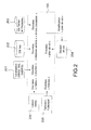
- the device comprises means for determining parameters characterizing the detected aircraft 101 from data coming from the sensors for the detection of surrounding aircraft.
- the sensors that can be used for the detection of surrounding aircraft are, for example: a TCAS, a radar, an Optronics sensor, an infrared sensor or a data link (for example ADS-B or link 16). These data make it possible to consider aircraft detected near the aircraft, in the given time horizon (for example two minutes)
- This module characterizes the dimensioning parameters of the aircraft detected by consolidating the data received from the various sensors.
- the parameters characterizing a detected aircraft comprise: (i) a detected type of aircraft, (ii) a 3D reference position of the aircraft, (iii) a prediction of displacement of the aircraft in the form of a predicted 4D trajectory starting from the reference point and (iv) the consolidated detection means for developing the reference position and the prediction of the displacement of the aircraft, for example, a radar, a TCAS, an ADS-B collaboration, a data link received from the ground or from a control aircraft (of the 16-link type, for example), optronic, infra-red.
- the characterization makes it possible to estimate the type of aircraft nearby and its future trajectory in order to be able to define the rules of the air, the margins and the applicable priorities.
- the device comprises means for determining parameters characterizing the detected weather phenomena, 102 from meteorological data coming from the weather sensors.
- determining parameters characterizing the detected weather phenomena 102 from meteorological data coming from the weather sensors.
- various sources of meteorological information for example, a WXR radar and a weather data link, it is estimated the type of phenomenon in the vicinity of the aircraft.
- the types of phenomena detected are among: the predicted windshear zones, the areas of turbulence, thunderstorms, storms and areas of volcanic eruptions (or eruptive dusts).
- the volume parameter can be any three-dimensional volume (polyhedron, sphere, ).
- the temporal evolution laws of the volume are then based, for example, on the vertices of the polyhedron.
- the device comprises means for calculating forbidden zones and their evolution over time 103 from the parameters characterizing the aircraft and the meteorological phenomena detected. Depending on the type of aircraft or weather phenomenon detected, it is possible to calculate lateral margins, vertical margins, an estimate of the deviation, an increase in the margins as a function of time and the confidence in the measurement and the estimated speed / direction.
- the figure 4 illustrates a prohibited zone associated with a glider-type aircraft.
- the forbidden zone of a mobile whose speed vector is known only and whose velocity vector is not known is defined by a succession of concentric circles whose radii 402, 403 obey an increasing law as a function of time and whose center is the position 401 of said mobile.
- the trajectory associated with a glider not being predictable, the calculated forbidden zone forms a circle whose radius is increasing in time.
- the prohibited volume is represented by a restriction zone of r i seconds around the initial position of the glider 401.
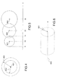
- the figure 5 illustrates a prohibited zone associated with a transport aircraft type aircraft whose speed vector is known.
- the secure volume is represented by a restriction area of r i seconds.
- the restriction zones rays meet the following formula: r ⁇ + r i + 1> p. In this way, the restriction zones partially overlap, while simplifying sampling and limiting the need for computing resources.
- the figure 5 illustrates the restriction zone at three different dates. All three samples are taken at 10-second intervals. The center of this zone is the predicted position of a detected aircraft calculated with the speed vector of said aircraft.
- a first point 501 represents the position of the aircraft at a date of 10 seconds.
- a second 502 and a third point 503 respectively represent the position of the aircraft at a date of 20 seconds and a date of 30 seconds.
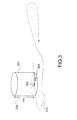
- the figure 6 illustrates a prohibited zone associated with an aircraft whose trajectory is known.
- the forbidden zone is defined, for example, by: a tube enveloping a plane of flight provided on the horizontal plane 601 having a radius corresponding to a measurement 602 of the variation of the parameters on a given period, for example 15 seconds.
- the principle is to estimate the maximum deviation measured with respect to the flight plan in the near past, for example one minute. The deviation is measured laterally and vertically. We keep a certain percentage, for example 95%, of the maximum measured.
- the forbidden zone can also be defined by a rectangular parallelepiped corresponding to a corridor around the horizontal trajectory and a fixed height margin around the vertical description of the 3D part.
- a rectangular parallelepiped makes it possible to estimate the lateral and vertical deviations independently, according to the same principle.
- the device comprises means for the calculation of zones, in four dimensions, reachable by the aircraft 104 from the position of the aircraft, data describing restricted zones prohibited to navigation, a model digital terrain, a list of obstacles and calculated prohibited areas.
- FR 2 910 640 an estimation method, for a mobile subject to constraints of vertical trajectory profile and risk minimization, of the distances of the points of a map obtained by projection on a horizontal plane of a 3D representation of a space of evolution by a mesh of elementary cubes associated with danger levels and identified by an altitude, a latitude and a longitude.
- this method does not take into account dynamic weather phenomena and mobiles whose position changes over time.
- the means for the four-dimensional attainable zone calculation according to the invention satisfies, at each propagation step, in addition to the criteria described in the aforementioned application, if, for a given 3D position and a considered date, the aircraft is more than a certain distance (horizontal separation and vertical separation) of a mobile or weather phenomenon predicted on date t.
- the time step on mobile sampling and weather phenomena is expanded according to separation margins. For example, mobiles and weather phenomena are predicted in steps of 15 seconds.
- the process described in the patent application FR 2 910 640 implements a distance transform operating by propagation on a 2D image of the map whose pixels arranged in rows and columns by orders of values of longitude and latitude correspond to the columns of cubes elementary of the mesh of the representation of the space of d and identify, for each column, forbidden altitude ranges corresponding to the cubes associated with danger levels higher than a permissible value for their crossing.
- This transform of distance estimates the distances of different points of the image from a source point placed near the mobile by applying, by scanning, a chamfer mask at different points of the image.
- the distance estimation of a point, by application of the chamfer mask at this point said goal point is carried out by listing the various paths from the point of the point of source to the point and passing through points of the neighborhood of the point of purpose that are covered by the chamfer mask and whose distances to the source point were previously estimated during the same scan, by determining the lengths of the different paths listed by summing the distance assigned to the neighborhood's crossing point and its distance to the extracted point of aim of the chamfer mask, looking for the shortest path among the listed paths and adopting its length as an estimate of the distance from the goal point.
- a distance value greater than the largest distance measurable on the image is attributed to all the points of the image except at the source point, the origin of the distance measurements, which is assigned a distance value. nothing.
- the lengths of the paths listed, when the chamfer mask is applied to a goal point, with a view to finding the shortest path, are translated into travel time for the mobile and the routes listed, including the travel times. for the mobile are such that it would reach the goal point in an elementary cube of the representation of the evolution space whose danger level is higher than a permissible value, are excluded from the search of the shortest path.
- a propagation distance transform estimates the distance of a pixel called "goal" pixel with respect to a so-called “source” pixel pixel by progressively building, starting from the source pixel, the shortest possible path following the mesh of the pixels and ending in the goal pixel, with the aid of the distances found for the pixels of the image already analyzed and a table called chamfer mask listing the values distances between a pixel and its close neighbors.
- a chamfer mask is in the form of a table with a layout of boxes reproducing the pattern of a pixel surrounded by his close neighbors.
- a box with a value of 0 marks the pixel taken as the origin of the distances listed in the table.
- Around this central box agglomerate peripheral boxes filled with non-zero distance values and taking again the disposition of the pixels of the neighborhood of a pixel supposed to occupy the central box.
- the distance value in a peripheral box is that of the distance separating a pixel occupying the position of the relevant peripheral box from a pixel occupying the position of the central box. Note that the distance values are distributed in concentric circles.
- a third circle of eight boxes corresponding to the eight pixels closest to the pixel of the central box, placed outside the row, the column and the diagonals of the pixel of the central box, are assigned a value D3.
- the chamfer mask can cover a more or less extended neighborhood of the pixel of the central square by listing the values of the distances of a greater or lesser number of concentric circles of pixels of the neighborhood. It can be reduced to the first two circles formed by the pixels of the neighborhood of a pixel occupying the central cell or be extended beyond the first three circles formed by the pixels of the neighborhood of the pixel of the central cell, but it is usual to stop at first three circles as is the case of the chamfer mask shown in figure 7 .
- the values of the distances D1, D2, D3 which correspond to Euclidean distances are expressed in a scale allowing the use of integers at the price of a certain approximation.
- the gradual construction of the shortest possible path to a goal pixel, starting from a source pixel and following the pixel mesh is done by regular scanning of the pixels of the image by means of the chamfer mask.
- the pixels of the image are assigned an infinite distance value, in fact a sufficiently high number to exceed all the values of the measurable distances in the image, with the exception of the source pixel which is assigned a value of zero distance.
- the initial distance values assigned to the goal points are updated during the scanning of the image by the chamfer mask, an update consisting in replacing a distance value assigned to a goal point with a new lower value. resulting from a distance estimation made on the occasion of a new application of the chamfer mask at the point of interest considered.
- a distance estimation by applying the chamfer mask to a goal pixel consists in listing all the paths going from this goal pixel to the source pixel and passing through a pixel of the neighborhood of the goal pixel whose distance has already been estimated during the same scan , to search among the listed routes, the shortest path (s) and to adopt the length of the shortest path (s) as the distance estimate.
- the scanning order of the pixels in the image affects the reliability of the distance estimates and their updates because the paths taken into account depend on them. In fact, it is subject to a regularity constraint that if the pixels of the image are spotted according to the lexicographic order (pixels ranked in increasing order line by line starting from the top of the image and progressing down the image, and from left to right within a line), and if a pixel was analyzed before a pixel q then a pixel p + x must be analyzed before the pixel q + x.
- Lexicographic orders inverse lexicography (scanning of the pixels of the image line by line from bottom to top and, within a line, from right to left), transposed lexicography (scanning of the pixels of the image column by column of left to right and, in a column, from top to bottom), inverse transposed lexicographic (scanning of pixels by columns from right to left and within a column from bottom to top) satisfy this regularity requirement and more typically all scans in which rows and columns are scanned from right to left or from left to right.
- Borgefors advocates a double scan of pixels in the image, once in the lexicographic order and another in the inverse lexicographic order.
- the figure 8a shows, in the case of a scan pass in the lexicographic order from the upper left corner to the lower right corner of the image, the boxes of the chamfer mask of the figure 1 used to list the paths from a goal pixel placed under the central box (box indexed by 0) to the source pixel through a neighborhood pixel whose distance has already been estimated during the same scan .
- These boxes are eight in number, arranged in the upper left part of the chamfer mask. There are thus eight paths listed for the shortest search whose length is taken for estimation of the distance.
- the figure 8b shows, in the case of a scanning pass in the inverse lexicographic order from the lower right corner to the upper left corner of the image, the boxes of the chamfer mask of the figure 1 used to list the paths from a goal pixel placed under the central box (box indexed by 0) to the source pixel through a neighborhood pixel whose distance has already been estimated during the same scan .
- These boxes are complementary to those of the figure 8a . They are also eight in number but arranged in the lower right part of the chamfer mask. There are thus still eight paths listed for the search of the shortest whose length is taken for estimation of the distance.
- the propagation distance transform of which the principle has just been summarily recalled was originally conceived for the analysis of the positioning of objects in an image but it was not slow to be applied to the estimation of the distances on a relief map extracted from a database of elevation of the land with regular mesh of the terrestrial surface. Indeed, such a map does not explicitly have a metric since it is drawn from the altitudes of the points of the mesh of the elevation database of the terrain of the zone represented.
- the propagation distance transform is applied to an image whose pixels are the elements of the terrain elevation database belonging to the map, that is to say, associated altitude values. to the geographical coordinates latitude, longitude of the nodes of the mesh where they were measured, classified, as on the map, by latitude and by longitude increasing or decreasing according to a two-dimensional array of latitude and longitude coordinates.
- the evolution of the impassable zones according to the vertical profile imposed on the trajectory of the aircraft is taken into account by means of the foreseeable altitude of the aircraft at each goal point whose distance is currently being estimated.
- This predictable altitude which obviously depends on the path taken, is that of the aircraft after tracking the path adopted for the distance measurement.
- the estimate of this foreseeable altitude of the aircraft at a goal point is done by propagation during the scanning of the image by the chamfer mask in a manner similar to the distance estimation.
- the Predictable altitude of the aircraft is deduced from the length of the path and the vertical profile imposed on the trajectory of the aircraft. This predicted altitude, estimated for each listed route from an aiming point whose distance is being estimated to a source point placed near the position of the aircraft, is used as a selection criterion for the trips taken in account in the distance estimation.
- the listed route with which it is associated is discarded and does not participate in the selection of the shortest route.
- a profile showing the date according to the distance from the origin This profile is obtained, for example, by integrating the speed provided by the flight management system along the flight plan or by making assumptions of speed (constant, for example). So, from the estimated distance, we can deduce the date at which we should be at this distance.
- a rejoining point selected is a point in the initial flight plan remaining attainable despite the multiple constraints of the aircraft and surrounding weather events. In addition, there must be a flight plan to reach this point, compatible with the available fuel resources.
- the initial trajectory is formed by the points A, B, C, D, E and F.
- the rejoining trajectory is formed by the points B ', C', D 'and E.
- a first quality criterion is the maximization of the number of crossing points of the initial flight plan retained.
- the rejoining path of the example retains three points of the initial trajectory: A, E and F.
- a second quality criterion is the minimization of the amount of total turn equal to the sum in absolute value of all course changes.
- a third quality criterion concerns a measure of the ratio between the initial trajectory and the new trajectory evaluated.
- a rejoin flight plan is even better than its length is close to that of the initial flight plan.
- a fourth quality criterion is the minimization of the joining angle of the initial flight plan. This is the angle formed by the rejoining trajectory and the initial trajectory at the rejoining point. In the example, this is the angle ⁇ between the flight segment D'E and the segment EF.
- a fifth quality criterion is the minimization of the deviation surface from the initial flight plan.
- the deviation surface is defined by its perimeter composed of the initial trajectory and the rejoining trajectory. In the example, it is the polygon surface B, C, D, E, D ', C', B '.
- the powers can be adjusted differently.
- a military application will try to limit the number of points removed and the area between the two paths.
- an application for a medical helicopter will try to limit the difference in distance between the trajectories, even if the crossing points are different.
- FIGS. 11a to 11e show examples of curves to standardize the different quality criteria presented. These curves make it possible to associate with each value of a criterion a score, between 0 and 1, reflecting its quality, 0 being the worst and 1 the best.
- the figure 11 a shows an example of the ratings assigned to a joined flight plan based on the number of waypoints retained in relation to an initial flight plan. Between 0 and 3 points preserved the note is null, for 4 points preserved the note is 0,5. Beyond 5 points, the score is 1.
- the figure 11 b shows an example of the ratings assigned to a joined flight plan based on its total turn quantity.
- the rating is 1 to 0 degrees. Between 0 and 360 degrees the note decreases linearly. The rating is 0 beyond 720 degrees. Between 360 and 720 degrees, the note decreases linearly.
- the figure 11 c shows an example of the ratings assigned to a joined flight plan based on the ratio of the length of the initial trajectory to its length. Between 0 and 0.8 the rating is zero. Between 0.8 and 1 the note grows linearly. For 1 the rating is 1. Above 1.5 the rating is zero. Between 1 and 1.5 the score decreases linearly.
- the figure 11d shows an example of the ratings assigned to a joined flight plan based on the flight plan rejection angle. Between 0 and 30 degrees the rating is 1. Above 120 degrees the score is 0. Between 30 and 120 degrees the score decreases linearly.
- the figure 11 e shows an example of the ratings assigned to a joined flight plan based on the deviation area from the initial flight plan. Among all the candidates, we take the smallest as a reference. The others are expressed as a percentage of this reference area. At 100% the rating is 1. Above 200% the rating is 0. Between 100% and 200% the rating decreases linearly.
- the device according to the invention comprises means for the calculation of a rejection flight plan towards the selected rejoin point 106. This calculation step is based on a method described in the French patent. 2,894,367 developing the "return" distance map from the selected destination position.
- the calculation of a joined flight plan described above can be repeated at regular intervals.
- the current flight plan of the aircraft is not updated for every iteration of the calculation.
- the current flight plan is kept as long as, on the one hand, it remains valid and, on the other hand, as long as the gain on the quality criterion of the new flight plan calculated in relation to the current flight plan is less than one given threshold.
Landscapes
- Engineering & Computer Science (AREA)
- Aviation & Aerospace Engineering (AREA)
- Physics & Mathematics (AREA)
- General Physics & Mathematics (AREA)
- Traffic Control Systems (AREA)
- Navigation (AREA)
Applications Claiming Priority (1)
| Application Number | Priority Date | Filing Date | Title |
|---|---|---|---|
| FR0805767A FR2937453B1 (fr) | 2008-10-17 | 2008-10-17 | Dispositif pour le calcul d'un plan de vol d'un aeronef |
Publications (2)
| Publication Number | Publication Date |
|---|---|
| EP2178065A1 true EP2178065A1 (de) | 2010-04-21 |
| EP2178065B1 EP2178065B1 (de) | 2011-03-09 |
Family
ID=40673612
Family Applications (1)
| Application Number | Title | Priority Date | Filing Date |
|---|---|---|---|
| EP09172684A Active EP2178065B1 (de) | 2008-10-17 | 2009-10-09 | Vorrichtung zum Berechnen eines Flugplans für ein Flugzeug |
Country Status (5)
| Country | Link |
|---|---|
| US (1) | US8275499B2 (de) |
| EP (1) | EP2178065B1 (de) |
| AT (1) | ATE501499T1 (de) |
| DE (1) | DE602009000847D1 (de) |
| FR (1) | FR2937453B1 (de) |
Cited By (1)
| Publication number | Priority date | Publication date | Assignee | Title |
|---|---|---|---|---|
| EP3379200A3 (de) * | 2017-03-21 | 2018-11-07 | Thales | Verfahren zum regulieren des korrekturkurses für luftfahrzeug |
Families Citing this family (53)
| Publication number | Priority date | Publication date | Assignee | Title |
|---|---|---|---|---|
| FR2920580B1 (fr) * | 2007-08-31 | 2010-09-03 | Thales Sa | Procede de simplification de l'affichage d'elements stationnaires d'une base de donnees embarquee |
| FR2953302B1 (fr) * | 2009-11-27 | 2012-08-10 | Thales Sa | Procede de planification, de calcul de trajectoire, de predictions et de guidage pour le respect d'une contrainte de temps de passage d'un aeronef |
| FR2968442B1 (fr) * | 2010-12-07 | 2012-12-28 | Airbus Operations Sas | Procede et dispositif pour aider a l'evaluation d'une trajectoire de vol destinee a etre suivie par un aeronef dans un environnement contraint. |
| FR2968441B1 (fr) * | 2010-12-07 | 2012-12-28 | Airbus Operations Sas | Procede et dispositif pour construire une trajectoire de vol optimale destinee a etre suivie par un aeronef. |
| US8494766B2 (en) * | 2011-01-07 | 2013-07-23 | Ge Aviation Systems, Llc | Flight management system with integrated tactical commands for use with an aircraft and method of operating same |
| FR2985353B1 (fr) | 2011-12-29 | 2014-02-07 | Thales Sa | Dispositif d'aide a la gestion d'un vol d'un aeronef |
| US20130226373A1 (en) * | 2012-02-27 | 2013-08-29 | Ge Aviation Systems Llc | Methods for in-flight adjusting of a flight plan |
| US8660719B2 (en) * | 2012-03-01 | 2014-02-25 | The Boeing Company | Four-dimensional flyable area display system for aircraft |
| RU2519622C2 (ru) * | 2012-03-19 | 2014-06-20 | Игорь Николаевич Кочергин | Автоматическая инструментальная система передачи метеорологических характеристик аэродрома и ввода их в пилотажно-навигационный комплекс управления полетом самолета |
| FR2990290B1 (fr) * | 2012-05-02 | 2015-04-03 | Sagem Defense Securite | Procede d'evitement d'un aeronef et drone equipe d'un systeme mettant en oeuvre ce procede |
| FR2994010B1 (fr) * | 2012-07-27 | 2018-09-07 | Thales | Dispositif et procede de gestion de strategie de rejointe de points de navigation |
| EP2733560A1 (de) * | 2012-11-19 | 2014-05-21 | The Boeing Company | Autonome Missionsverwaltung |
| US8843303B1 (en) * | 2012-12-17 | 2014-09-23 | Rockwell Collins, Inc. | Risk-aware contingency flight re-planner system and related method |
| US9424752B1 (en) | 2012-12-26 | 2016-08-23 | Google Inc. | Methods and systems for performing fleet planning based on coarse estimates of regions |
| US9747568B1 (en) | 2012-12-26 | 2017-08-29 | X Development Llc | Methods and systems for determining when to decommission vehicles from a fleet of autonomous vehicles |
| US8849571B1 (en) | 2012-12-26 | 2014-09-30 | Google Inc. | Methods and systems for determining fleet trajectories with phase-skipping to satisfy a sequence of coverage requirements |
| US9195938B1 (en) | 2012-12-27 | 2015-11-24 | Google Inc. | Methods and systems for determining when to launch vehicles into a fleet of autonomous vehicles |
| US8948927B1 (en) | 2012-12-27 | 2015-02-03 | Google Inc. | Methods and systems for determining a distribution of balloons based on population densities |
| US8862403B1 (en) | 2012-12-28 | 2014-10-14 | Google Inc. | Methods and systems for determining altitudes for a vehicle to travel |
| US9014957B2 (en) | 2012-12-29 | 2015-04-21 | Google Inc. | Methods and systems for determining fleet trajectories to satisfy a sequence of coverage requirements |
| US9635706B1 (en) | 2013-01-02 | 2017-04-25 | X Development Llc | Method for determining fleet control policies to satisfy a sequence of coverage requirements |
| US8781727B1 (en) | 2013-01-15 | 2014-07-15 | Google Inc. | Methods and systems for performing flocking while executing a long-range fleet plan |
| US8874356B1 (en) | 2013-01-24 | 2014-10-28 | Google Inc. | Methods and systems for decomposing fleet planning optimizations via spatial partitions |
| US8880326B1 (en) | 2013-02-20 | 2014-11-04 | Google Inc. | Methods and systems for determining a cyclical fleet plan satisfying a recurring set of coverage requirements |
| US9177479B2 (en) * | 2013-03-13 | 2015-11-03 | General Electric Company | System and method for determining aircraft operational parameters and enhancing aircraft operation |
| US8798815B1 (en) | 2013-03-13 | 2014-08-05 | Honeywell International Inc. | System and method alerting an aircrew of threshold altitudes |
| US9417070B1 (en) * | 2013-04-01 | 2016-08-16 | Nextgen Aerosciences, Inc. | Systems and methods for continuous replanning of vehicle trajectories |
| US9201426B1 (en) * | 2014-02-19 | 2015-12-01 | Google Inc. | Reverse iteration of planning data for system control |
| FR3022045B1 (fr) * | 2014-06-06 | 2016-05-27 | Thales Sa | Procede et dispositif de determination du sens de virage optimal d'un aeronef |
| US10339816B2 (en) * | 2014-06-27 | 2019-07-02 | The Boeing Company | Automatic aircraft monitoring and operator preferred rerouting system and method |
| US20160140851A1 (en) * | 2014-11-18 | 2016-05-19 | Ziv LEVY | Systems and methods for drone navigation |
| US20160307447A1 (en) | 2015-02-13 | 2016-10-20 | Unmanned Innovation, Inc. | Unmanned aerial vehicle remote flight planning system |
| EP3062551B1 (de) * | 2015-02-27 | 2019-03-27 | Mitsubishi Electric R&D Centre Europe B.V. | Verfahren zur Schätzung der mit Downlink-Kommunikation in Richtung einer Kommunikationsvorrichtung in einem sich bewegenden Beförderungsmittel zu erwartenden Interferenzen |
| US10937326B1 (en) * | 2015-10-05 | 2021-03-02 | 5X5 Technologies, Inc. | Virtual radar system for unmanned aerial vehicles |
| CN106599565B (zh) * | 2016-12-07 | 2018-11-06 | 中国电子科技集团公司第五十四研究所 | 基于位置时-距分层的通航飞行器越界高效监视方法 |
| US20180286253A1 (en) * | 2017-03-31 | 2018-10-04 | General Electric Company | Optimized aircraft control via model-based iterative optimization |
| US10460608B2 (en) * | 2017-05-25 | 2019-10-29 | Ge Aviation Systems Llc | System and method for determining uncertainty in a predicted flight path for an aerial vehicle |
| US10573186B2 (en) | 2017-12-12 | 2020-02-25 | Honeywell International Inc. | System and method for monitoring conformance of an aircraft to a reference 4-dimensional trajectory |
| GB2574001B (en) * | 2018-05-18 | 2022-08-17 | Univ Bath | Apparatus, method and system relating to aircraft systems |
| GB2577064B (en) | 2018-09-11 | 2021-03-24 | Satavia Ltd | System and method for aircraft flight planning |
| JP2021168005A (ja) * | 2020-04-09 | 2021-10-21 | エスゼット ディージェイアイ テクノロジー カンパニー リミテッドSz Dji Technology Co., Ltd | 表示制御方法、表示制御装置、プログラム、及び記録媒体 |
| US11790789B2 (en) | 2020-06-05 | 2023-10-17 | Honeywell International Inc. | Gliding vertical margin guidance methods and systems |
| US20220128364A1 (en) * | 2020-10-27 | 2022-04-28 | International Business Machines Corporation | Navigation guidance |
| FR3121983B1 (fr) * | 2021-04-14 | 2023-04-14 | Thales Sa | Adaptation automatique du profil vertical d’un aéronef en fonction d’une incertitude de position |
| US11790790B2 (en) * | 2022-01-13 | 2023-10-17 | Beta Air, Llc | Methods and apparatuses for generating an electric aircraft flight plan |
| EP4270361A1 (de) * | 2022-04-27 | 2023-11-01 | The Boeing Company | Systeme und verfahren zum aktualisieren von flugplänen basierend auf geregelten bereichen |
| CN114636417B (zh) * | 2022-05-23 | 2022-09-02 | 珠海翔翼航空技术有限公司 | 基于图像识别的飞行器迫降路径规划方法、系统和设备 |
| CN116414934B (zh) * | 2023-03-13 | 2025-10-17 | 中国电子科技集团公司第二十八研究所 | 一种基于时空网格的目标运行安全空域规划方法 |
| US20250037589A1 (en) * | 2023-07-24 | 2025-01-30 | Honeywell International Inc. | Autonomous protected flight zones during emergency operations of aerial vehicles |
| EP4524932A1 (de) * | 2023-09-13 | 2025-03-19 | Honeywell International Inc. | Verfahren und system zur erzeugung einer richtungsabfangempfehlung |
| US20250157342A1 (en) * | 2023-11-10 | 2025-05-15 | Wing Aviation Llc | UAV Route Planning for Mitigating Traffic Encounters |
| CN118824069B (zh) * | 2024-09-19 | 2024-12-17 | 西北工业大学 | 基于激光雷达的集群飞行器避障系统 |
| CN119714305B (zh) * | 2025-03-03 | 2025-04-29 | 国网四川省电力公司电力应急中心 | 一种多无人机协同巡检配网线路的航迹规划方法和系统 |
Citations (6)
| Publication number | Priority date | Publication date | Assignee | Title |
|---|---|---|---|---|
| DE19609613A1 (de) * | 1996-03-12 | 1997-09-18 | Vdo Luftfahrtgeraete Werk Gmbh | Verfahren zur Erkennung eines Kollisionsrisikos und zur Vermeidung von Kollisionen in der Luftfahrt |
| US6381538B1 (en) * | 2000-05-26 | 2002-04-30 | Aerotech Research (U.S.A.), Inc. | Vehicle specific hazard estimation, presentation, and route planning based on meteorological and other environmental data |
| FR2893146A1 (fr) | 2005-11-10 | 2007-05-11 | Thales Sa | Systeme d'evitement de terrain pour aeronefs de transport |
| FR2894367A1 (fr) | 2005-12-07 | 2007-06-08 | Thales Sa | Procede de determination du profil horizontal d'un plan de vol respectant un profil de vol vertical impose |
| FR2910640A1 (fr) | 2006-12-21 | 2008-06-27 | Thales Sa | Procede d'estimation de distance pour un mobile ayant un profil vertical de trajectoire contraint |
| US20080218384A1 (en) * | 2007-03-07 | 2008-09-11 | Honeywell International Inc. | Method and system for maintaining spatio-temporal data |
Family Cites Families (20)
| Publication number | Priority date | Publication date | Assignee | Title |
|---|---|---|---|---|
| US6199008B1 (en) * | 1998-09-17 | 2001-03-06 | Noegenesis, Inc. | Aviation, terrain and weather display system |
| US6744382B1 (en) * | 2002-04-19 | 2004-06-01 | Rockwell Collins | Method and apparatus for guiding an aircraft through a cluster of hazardous areas |
| FR2861478B1 (fr) | 2003-10-24 | 2006-04-14 | Thales Sa | Procede de determination des coefficients optimaux d'un masque de chanfrein pour transformee de distance |
| FR2864312B1 (fr) | 2003-12-19 | 2006-07-14 | Thales Sa | Carte de manoeuvrabilite laterale pour mobile et son procede d'obtention |
| FR2867270B1 (fr) | 2004-03-05 | 2006-06-23 | Thales Sa | Procede d'estimation de distance curviligne pour mobile a manoeuvrabilite limitee |
| FR2869106B1 (fr) | 2004-04-20 | 2006-06-23 | Thales Sa | Procede d'estimation de distance pour aeronef avec prise en compte de contraintes de navigation aerienne |
| FR2871878B1 (fr) | 2004-06-18 | 2006-09-01 | Thales Sa | Procede de signalisation des marges laterales de manoeuvre existant de part et d'autre de la trajectoire du plan de vol d'un aeronef |
| FR2871879B1 (fr) | 2004-06-18 | 2006-09-01 | Thales Sa | Procede d'evaluation et de signalisation des marges laterales de manoeuvre de part et d'autre de la trajectoire du plan de vol d'un aeronef |
| FR2875899B1 (fr) | 2004-09-24 | 2006-12-01 | Thales Sa | Dispositif et procede de signalisation de marges laterales de manoeuvre |
| FR2877721B1 (fr) | 2004-11-10 | 2007-01-19 | Thales Sa | Dispositif de representation cartographique des vitesses verticales minimales |
| FR2894368B1 (fr) | 2005-12-07 | 2008-01-25 | Thales Sa | Dispositif et procede de construction automatisee de trajectoire d'urgence pour aeronefs |
| ES2616545T3 (es) * | 2006-04-20 | 2017-06-13 | Saab Ab | Plan de vuelo de emergencia |
| ES2354300T3 (es) * | 2006-06-30 | 2011-03-11 | Saab Ab | Planificación de intinerario con terminación sin riesgos. |
| FR2906921B1 (fr) * | 2006-10-10 | 2010-08-13 | Thales Sa | Procede de formation d'une trajectoire d'urgence en 3d pour aeronef et dispositif de mise en oeuvre |
| FR2907541B1 (fr) | 2006-10-24 | 2009-01-16 | Thales Sa | Procede de gestion automatique de la vitesse d'un aeronef en air turbulent et dispositif pour sa mise en oeuvre |
| FR2908876B1 (fr) | 2006-11-21 | 2009-02-13 | Thales Sa | Procede de detection automatique de turbulence |
| FR2913503B1 (fr) | 2007-03-06 | 2009-07-17 | Thales Sa | Calculateur de gestion du vol a prise en compte de contrainte de vitesse d'approche |
| FR2921152B1 (fr) | 2007-09-14 | 2010-03-12 | Thales Sa | Procede d'assistance de rejointe de plan de vol d'aeronef par interception d'un segment de vol proche de l'aeronef |
| US8060295B2 (en) * | 2007-11-12 | 2011-11-15 | The Boeing Company | Automated separation manager |
| FR2923623B1 (fr) | 2007-11-13 | 2015-02-27 | Thales Sa | Systeme de securisation d'un plan de vol pour aeronef |
-
2008
- 2008-10-17 FR FR0805767A patent/FR2937453B1/fr not_active Expired - Fee Related
-
2009
- 2009-10-09 AT AT09172684T patent/ATE501499T1/de not_active IP Right Cessation
- 2009-10-09 EP EP09172684A patent/EP2178065B1/de active Active
- 2009-10-09 DE DE602009000847T patent/DE602009000847D1/de active Active
- 2009-10-14 US US12/579,272 patent/US8275499B2/en active Active
Patent Citations (6)
| Publication number | Priority date | Publication date | Assignee | Title |
|---|---|---|---|---|
| DE19609613A1 (de) * | 1996-03-12 | 1997-09-18 | Vdo Luftfahrtgeraete Werk Gmbh | Verfahren zur Erkennung eines Kollisionsrisikos und zur Vermeidung von Kollisionen in der Luftfahrt |
| US6381538B1 (en) * | 2000-05-26 | 2002-04-30 | Aerotech Research (U.S.A.), Inc. | Vehicle specific hazard estimation, presentation, and route planning based on meteorological and other environmental data |
| FR2893146A1 (fr) | 2005-11-10 | 2007-05-11 | Thales Sa | Systeme d'evitement de terrain pour aeronefs de transport |
| FR2894367A1 (fr) | 2005-12-07 | 2007-06-08 | Thales Sa | Procede de determination du profil horizontal d'un plan de vol respectant un profil de vol vertical impose |
| FR2910640A1 (fr) | 2006-12-21 | 2008-06-27 | Thales Sa | Procede d'estimation de distance pour un mobile ayant un profil vertical de trajectoire contraint |
| US20080218384A1 (en) * | 2007-03-07 | 2008-09-11 | Honeywell International Inc. | Method and system for maintaining spatio-temporal data |
Cited By (2)
| Publication number | Priority date | Publication date | Assignee | Title |
|---|---|---|---|---|
| EP3379200A3 (de) * | 2017-03-21 | 2018-11-07 | Thales | Verfahren zum regulieren des korrekturkurses für luftfahrzeug |
| US10854094B2 (en) | 2017-03-21 | 2020-12-01 | Thales | Rejoining trajectory adjustment method for aircraft |
Also Published As
| Publication number | Publication date |
|---|---|
| FR2937453B1 (fr) | 2010-10-22 |
| ATE501499T1 (de) | 2011-03-15 |
| DE602009000847D1 (de) | 2011-04-21 |
| EP2178065B1 (de) | 2011-03-09 |
| US20100100308A1 (en) | 2010-04-22 |
| US8275499B2 (en) | 2012-09-25 |
| FR2937453A1 (fr) | 2010-04-23 |
Similar Documents
| Publication | Publication Date | Title |
|---|---|---|
| EP2178065B1 (de) | Vorrichtung zum Berechnen eines Flugplans für ein Flugzeug | |
| EP1958176B1 (de) | Verfahren zur bestimmung des horizontalen profils eines flugplans in entsprechung mit einem vorgeschriebenen vertikal-flugprofil | |
| US10706729B2 (en) | Joint search method for UAV multiobjective path planning in urban low altitude environment | |
| US8234068B1 (en) | System, module, and method of constructing a flight path used by an avionics system | |
| CN102645931B (zh) | 用于选择气象数据以用于更新飞行器轨迹的方法 | |
| CA2796923C (en) | Determining landing sites for aircraft | |
| CN103941744B (zh) | 用于确定飞行路径的方法 | |
| EP3994678A1 (de) | Verfahren zur bestimmung des wegs einer unbemannten luftvorrichtung und andere zugehörige verfahren | |
| FR3038999A1 (fr) | Systeme et procede pour affiner des trajectoires pour des aeronefs | |
| FR3021107A1 (fr) | Procede d'aide a la navigation d'un aeronef avec correlation d'informations dynamiques avec une trajectoire de vol 4d | |
| CA2853546A1 (en) | Identification and analysis of aircraft landing sites | |
| FR2926894A1 (fr) | Procede d'estimation en tout point d'un trajet d'un aeronef des donnees atmospheriques | |
| Kealy et al. | Collaborative navigation as a solution for PNT applications in GNSS challenged environments–report on field trials of a joint FIG/IAG working group | |
| FR3038750A1 (fr) | Procede d'integration d'un nouveau service de navigation dans un systeme avionique embarque a architecture ouverte de type client-serveur, en particulier d'un service de manoeuvre fim | |
| CN119886491B (zh) | 一种多模态协作的光伏电站巡检方法及系统 | |
| US20230408288A1 (en) | Method and apparatus for determining navigation routes based on weather manipulation data | |
| EP0453327B1 (de) | Methode zur Lenkung eines Flugzeuges im Tiefflug | |
| WO2000039775A2 (fr) | Systeme d'aide a l'evitement de collisions d'aeronefs avec le terrain | |
| FR3038751A1 (fr) | Procede d'integration d'une application d'optimisation de route (s) sous contraintes dans un systeme embarque avionique a architecture ouverte de type client serveur | |
| EP3770555B1 (de) | Navigation, die auf einer ausstrahlung für multiagenten basiert | |
| Romanov et al. | Automated mission planning for aerial large‐scale power plant thermal inspection | |
| WO2022219007A1 (fr) | Adaptation automatique du profil vertical d'un aeronef en fonction d'une incertitude de position | |
| FR3120266A1 (fr) | Système électronique d’aide au pilotage d’un drone, procédé et programme d’ordinateur associés | |
| FR3150872A1 (fr) | Procédé de calcul et/ou de surveillance du fonctionnement d'un système de positionnement par satellites embarqué dans un véhicule, et dispositif et produit programme d'ordinateur associés | |
| Che Mat et al. | Surf zone mapping using multirotor unmanned aerial vehicle imagery |
Legal Events
| Date | Code | Title | Description |
|---|---|---|---|
| PUAI | Public reference made under article 153(3) epc to a published international application that has entered the european phase |
Free format text: ORIGINAL CODE: 0009012 |
|
| AK | Designated contracting states |
Kind code of ref document: A1 Designated state(s): AT BE BG CH CY CZ DE DK EE ES FI FR GB GR HR HU IE IS IT LI LT LU LV MC MK MT NL NO PL PT RO SE SI SK SM TR |
|
| AX | Request for extension of the european patent |
Extension state: AL BA RS |
|
| 17P | Request for examination filed |
Effective date: 20100507 |
|
| 17Q | First examination report despatched |
Effective date: 20100528 |
|
| GRAP | Despatch of communication of intention to grant a patent |
Free format text: ORIGINAL CODE: EPIDOSNIGR1 |
|
| GRAS | Grant fee paid |
Free format text: ORIGINAL CODE: EPIDOSNIGR3 |
|
| GRAA | (expected) grant |
Free format text: ORIGINAL CODE: 0009210 |
|
| AK | Designated contracting states |
Kind code of ref document: B1 Designated state(s): AT BE BG CH CY CZ DE DK EE ES FI FR GB GR HR HU IE IS IT LI LT LU LV MC MK MT NL NO PL PT RO SE SI SK SM TR |
|
| REG | Reference to a national code |
Ref country code: GB Ref legal event code: FG4D Free format text: NOT ENGLISH |
|
| REG | Reference to a national code |
Ref country code: CH Ref legal event code: EP |
|
| REG | Reference to a national code |
Ref country code: IE Ref legal event code: FG4D Free format text: LANGUAGE OF EP DOCUMENT: FRENCH |
|
| REF | Corresponds to: |
Ref document number: 602009000847 Country of ref document: DE Date of ref document: 20110421 Kind code of ref document: P |
|
| REG | Reference to a national code |
Ref country code: DE Ref legal event code: R096 Ref document number: 602009000847 Country of ref document: DE Effective date: 20110421 |
|
| REG | Reference to a national code |
Ref country code: SE Ref legal event code: TRGR |
|
| REG | Reference to a national code |
Ref country code: NL Ref legal event code: VDEP Effective date: 20110309 |
|
| PG25 | Lapsed in a contracting state [announced via postgrant information from national office to epo] |
Ref country code: LV Free format text: LAPSE BECAUSE OF FAILURE TO SUBMIT A TRANSLATION OF THE DESCRIPTION OR TO PAY THE FEE WITHIN THE PRESCRIBED TIME-LIMIT Effective date: 20110309 Ref country code: ES Free format text: LAPSE BECAUSE OF FAILURE TO SUBMIT A TRANSLATION OF THE DESCRIPTION OR TO PAY THE FEE WITHIN THE PRESCRIBED TIME-LIMIT Effective date: 20110620 Ref country code: HR Free format text: LAPSE BECAUSE OF FAILURE TO SUBMIT A TRANSLATION OF THE DESCRIPTION OR TO PAY THE FEE WITHIN THE PRESCRIBED TIME-LIMIT Effective date: 20110309 Ref country code: GR Free format text: LAPSE BECAUSE OF FAILURE TO SUBMIT A TRANSLATION OF THE DESCRIPTION OR TO PAY THE FEE WITHIN THE PRESCRIBED TIME-LIMIT Effective date: 20110610 Ref country code: LT Free format text: LAPSE BECAUSE OF FAILURE TO SUBMIT A TRANSLATION OF THE DESCRIPTION OR TO PAY THE FEE WITHIN THE PRESCRIBED TIME-LIMIT Effective date: 20110309 Ref country code: NO Free format text: LAPSE BECAUSE OF FAILURE TO SUBMIT A TRANSLATION OF THE DESCRIPTION OR TO PAY THE FEE WITHIN THE PRESCRIBED TIME-LIMIT Effective date: 20110609 |
|
| LTIE | Lt: invalidation of european patent or patent extension |
Effective date: 20110309 |
|
| PG25 | Lapsed in a contracting state [announced via postgrant information from national office to epo] |
Ref country code: CY Free format text: LAPSE BECAUSE OF FAILURE TO SUBMIT A TRANSLATION OF THE DESCRIPTION OR TO PAY THE FEE WITHIN THE PRESCRIBED TIME-LIMIT Effective date: 20110309 Ref country code: AT Free format text: LAPSE BECAUSE OF FAILURE TO SUBMIT A TRANSLATION OF THE DESCRIPTION OR TO PAY THE FEE WITHIN THE PRESCRIBED TIME-LIMIT Effective date: 20110309 Ref country code: NL Free format text: LAPSE BECAUSE OF FAILURE TO SUBMIT A TRANSLATION OF THE DESCRIPTION OR TO PAY THE FEE WITHIN THE PRESCRIBED TIME-LIMIT Effective date: 20110309 Ref country code: FI Free format text: LAPSE BECAUSE OF FAILURE TO SUBMIT A TRANSLATION OF THE DESCRIPTION OR TO PAY THE FEE WITHIN THE PRESCRIBED TIME-LIMIT Effective date: 20110309 Ref country code: BG Free format text: LAPSE BECAUSE OF FAILURE TO SUBMIT A TRANSLATION OF THE DESCRIPTION OR TO PAY THE FEE WITHIN THE PRESCRIBED TIME-LIMIT Effective date: 20110609 Ref country code: SI Free format text: LAPSE BECAUSE OF FAILURE TO SUBMIT A TRANSLATION OF THE DESCRIPTION OR TO PAY THE FEE WITHIN THE PRESCRIBED TIME-LIMIT Effective date: 20110309 |
|
| REG | Reference to a national code |
Ref country code: IE Ref legal event code: FD4D |
|
| PG25 | Lapsed in a contracting state [announced via postgrant information from national office to epo] |
Ref country code: IE Free format text: LAPSE BECAUSE OF FAILURE TO SUBMIT A TRANSLATION OF THE DESCRIPTION OR TO PAY THE FEE WITHIN THE PRESCRIBED TIME-LIMIT Effective date: 20110309 Ref country code: EE Free format text: LAPSE BECAUSE OF FAILURE TO SUBMIT A TRANSLATION OF THE DESCRIPTION OR TO PAY THE FEE WITHIN THE PRESCRIBED TIME-LIMIT Effective date: 20110309 Ref country code: PT Free format text: LAPSE BECAUSE OF FAILURE TO SUBMIT A TRANSLATION OF THE DESCRIPTION OR TO PAY THE FEE WITHIN THE PRESCRIBED TIME-LIMIT Effective date: 20110711 |
|
| PG25 | Lapsed in a contracting state [announced via postgrant information from national office to epo] |
Ref country code: CZ Free format text: LAPSE BECAUSE OF FAILURE TO SUBMIT A TRANSLATION OF THE DESCRIPTION OR TO PAY THE FEE WITHIN THE PRESCRIBED TIME-LIMIT Effective date: 20110309 Ref country code: IS Free format text: LAPSE BECAUSE OF FAILURE TO SUBMIT A TRANSLATION OF THE DESCRIPTION OR TO PAY THE FEE WITHIN THE PRESCRIBED TIME-LIMIT Effective date: 20110709 Ref country code: RO Free format text: LAPSE BECAUSE OF FAILURE TO SUBMIT A TRANSLATION OF THE DESCRIPTION OR TO PAY THE FEE WITHIN THE PRESCRIBED TIME-LIMIT Effective date: 20110309 Ref country code: SK Free format text: LAPSE BECAUSE OF FAILURE TO SUBMIT A TRANSLATION OF THE DESCRIPTION OR TO PAY THE FEE WITHIN THE PRESCRIBED TIME-LIMIT Effective date: 20110309 |
|
| PLBE | No opposition filed within time limit |
Free format text: ORIGINAL CODE: 0009261 |
|
| STAA | Information on the status of an ep patent application or granted ep patent |
Free format text: STATUS: NO OPPOSITION FILED WITHIN TIME LIMIT |
|
| 26N | No opposition filed |
Effective date: 20111212 |
|
| PG25 | Lapsed in a contracting state [announced via postgrant information from national office to epo] |
Ref country code: PL Free format text: LAPSE BECAUSE OF FAILURE TO SUBMIT A TRANSLATION OF THE DESCRIPTION OR TO PAY THE FEE WITHIN THE PRESCRIBED TIME-LIMIT Effective date: 20110309 |
|
| REG | Reference to a national code |
Ref country code: DE Ref legal event code: R097 Ref document number: 602009000847 Country of ref document: DE Effective date: 20111212 |
|
| BERE | Be: lapsed |
Owner name: THALES Effective date: 20111031 |
|
| PG25 | Lapsed in a contracting state [announced via postgrant information from national office to epo] |
Ref country code: MC Free format text: LAPSE BECAUSE OF NON-PAYMENT OF DUE FEES Effective date: 20111031 |
|
| PG25 | Lapsed in a contracting state [announced via postgrant information from national office to epo] |
Ref country code: DE Free format text: LAPSE BECAUSE OF NON-PAYMENT OF DUE FEES Effective date: 20120501 Ref country code: BE Free format text: LAPSE BECAUSE OF NON-PAYMENT OF DUE FEES Effective date: 20111031 |
|
| REG | Reference to a national code |
Ref country code: DE Ref legal event code: R119 Ref document number: 602009000847 Country of ref document: DE Effective date: 20120501 |
|
| PG25 | Lapsed in a contracting state [announced via postgrant information from national office to epo] |
Ref country code: MT Free format text: LAPSE BECAUSE OF FAILURE TO SUBMIT A TRANSLATION OF THE DESCRIPTION OR TO PAY THE FEE WITHIN THE PRESCRIBED TIME-LIMIT Effective date: 20110309 Ref country code: MK Free format text: LAPSE BECAUSE OF FAILURE TO SUBMIT A TRANSLATION OF THE DESCRIPTION OR TO PAY THE FEE WITHIN THE PRESCRIBED TIME-LIMIT Effective date: 20110309 |
|
| PG25 | Lapsed in a contracting state [announced via postgrant information from national office to epo] |
Ref country code: SM Free format text: LAPSE BECAUSE OF FAILURE TO SUBMIT A TRANSLATION OF THE DESCRIPTION OR TO PAY THE FEE WITHIN THE PRESCRIBED TIME-LIMIT Effective date: 20110309 |
|
| PG25 | Lapsed in a contracting state [announced via postgrant information from national office to epo] |
Ref country code: LU Free format text: LAPSE BECAUSE OF NON-PAYMENT OF DUE FEES Effective date: 20111009 |
|
| PG25 | Lapsed in a contracting state [announced via postgrant information from national office to epo] |
Ref country code: TR Free format text: LAPSE BECAUSE OF FAILURE TO SUBMIT A TRANSLATION OF THE DESCRIPTION OR TO PAY THE FEE WITHIN THE PRESCRIBED TIME-LIMIT Effective date: 20110309 |
|
| PG25 | Lapsed in a contracting state [announced via postgrant information from national office to epo] |
Ref country code: HU Free format text: LAPSE BECAUSE OF FAILURE TO SUBMIT A TRANSLATION OF THE DESCRIPTION OR TO PAY THE FEE WITHIN THE PRESCRIBED TIME-LIMIT Effective date: 20110309 |
|
| REG | Reference to a national code |
Ref country code: CH Ref legal event code: PL |
|
| PG25 | Lapsed in a contracting state [announced via postgrant information from national office to epo] |
Ref country code: LI Free format text: LAPSE BECAUSE OF NON-PAYMENT OF DUE FEES Effective date: 20131031 Ref country code: CH Free format text: LAPSE BECAUSE OF NON-PAYMENT OF DUE FEES Effective date: 20131031 |
|
| REG | Reference to a national code |
Ref country code: FR Ref legal event code: PLFP Year of fee payment: 8 |
|
| REG | Reference to a national code |
Ref country code: FR Ref legal event code: PLFP Year of fee payment: 9 |
|
| REG | Reference to a national code |
Ref country code: FR Ref legal event code: PLFP Year of fee payment: 10 |
|
| PGFP | Annual fee paid to national office [announced via postgrant information from national office to epo] |
Ref country code: SE Payment date: 20181011 Year of fee payment: 10 |
|
| PGFP | Annual fee paid to national office [announced via postgrant information from national office to epo] |
Ref country code: GB Payment date: 20181001 Year of fee payment: 10 Ref country code: IT Payment date: 20181018 Year of fee payment: 10 |
|
| PG25 | Lapsed in a contracting state [announced via postgrant information from national office to epo] |
Ref country code: SE Free format text: LAPSE BECAUSE OF NON-PAYMENT OF DUE FEES Effective date: 20191010 |
|
| GBPC | Gb: european patent ceased through non-payment of renewal fee |
Effective date: 20191009 |
|
| PG25 | Lapsed in a contracting state [announced via postgrant information from national office to epo] |
Ref country code: GB Free format text: LAPSE BECAUSE OF NON-PAYMENT OF DUE FEES Effective date: 20191009 Ref country code: IT Free format text: LAPSE BECAUSE OF NON-PAYMENT OF DUE FEES Effective date: 20191009 |
|
| PGFP | Annual fee paid to national office [announced via postgrant information from national office to epo] |
Ref country code: FR Payment date: 20210930 Year of fee payment: 13 |
|
| P01 | Opt-out of the competence of the unified patent court (upc) registered |
Effective date: 20230427 |
|
| PG25 | Lapsed in a contracting state [announced via postgrant information from national office to epo] |
Ref country code: FR Free format text: LAPSE BECAUSE OF NON-PAYMENT OF DUE FEES Effective date: 20221031 |