EP2178098A1 - Schalter - Google Patents
Schalter Download PDFInfo
- Publication number
- EP2178098A1 EP2178098A1 EP08017964A EP08017964A EP2178098A1 EP 2178098 A1 EP2178098 A1 EP 2178098A1 EP 08017964 A EP08017964 A EP 08017964A EP 08017964 A EP08017964 A EP 08017964A EP 2178098 A1 EP2178098 A1 EP 2178098A1
- Authority
- EP
- European Patent Office
- Prior art keywords
- switch
- sensor
- switching
- movement
- switch according
- Prior art date
- Legal status (The legal status is an assumption and is not a legal conclusion. Google has not performed a legal analysis and makes no representation as to the accuracy of the status listed.)
- Granted
Links
Images
Classifications
-
- H—ELECTRICITY
- H01—ELECTRIC ELEMENTS
- H01H—ELECTRIC SWITCHES; RELAYS; SELECTORS; EMERGENCY PROTECTIVE DEVICES
- H01H23/00—Tumbler or rocker switches, i.e. switches characterised by being operated by rocking an operating member in the form of a rocker button
- H01H23/28—Tumbler or rocker switches, i.e. switches characterised by being operated by rocking an operating member in the form of a rocker button with three operating positions
- H01H23/30—Tumbler or rocker switches, i.e. switches characterised by being operated by rocking an operating member in the form of a rocker button with three operating positions with stable centre positions and one or both end positions unstable
-
- H—ELECTRICITY
- H01—ELECTRIC ELEMENTS
- H01H—ELECTRIC SWITCHES; RELAYS; SELECTORS; EMERGENCY PROTECTIVE DEVICES
- H01H3/00—Mechanisms for operating contacts
- H01H3/02—Operating parts, i.e. for operating driving mechanism by a mechanical force external to the switch
- H01H2003/0293—Operating parts, i.e. for operating driving mechanism by a mechanical force external to the switch with an integrated touch switch
-
- H—ELECTRICITY
- H01—ELECTRIC ELEMENTS
- H01H—ELECTRIC SWITCHES; RELAYS; SELECTORS; EMERGENCY PROTECTIVE DEVICES
- H01H21/00—Switches operated by an operating part in the form of a pivotable member acted upon directly by a solid body, e.g. by a hand
- H01H21/02—Details
- H01H21/18—Movable parts; Contacts mounted thereon
- H01H21/22—Operating parts, e.g. handle
- H01H2021/225—Operating parts, e.g. handle with push-pull operation, e.g. which can be pivoted in both directions by pushing or pulling on the same extremity of the operating member
-
- H—ELECTRICITY
- H01—ELECTRIC ELEMENTS
- H01H—ELECTRIC SWITCHES; RELAYS; SELECTORS; EMERGENCY PROTECTIVE DEVICES
- H01H2239/00—Miscellaneous
- H01H2239/03—Avoiding erroneous switching
-
- H—ELECTRICITY
- H01—ELECTRIC ELEMENTS
- H01H—ELECTRIC SWITCHES; RELAYS; SELECTORS; EMERGENCY PROTECTIVE DEVICES
- H01H2300/00—Orthogonal indexing scheme relating to electric switches, relays, selectors or emergency protective devices covered by H01H
- H01H2300/006—Application power roofs
-
- H—ELECTRICITY
- H01—ELECTRIC ELEMENTS
- H01H—ELECTRIC SWITCHES; RELAYS; SELECTORS; EMERGENCY PROTECTIVE DEVICES
- H01H2300/00—Orthogonal indexing scheme relating to electric switches, relays, selectors or emergency protective devices covered by H01H
- H01H2300/024—Avoid unwanted operation
-
- H—ELECTRICITY
- H01—ELECTRIC ELEMENTS
- H01H—ELECTRIC SWITCHES; RELAYS; SELECTORS; EMERGENCY PROTECTIVE DEVICES
- H01H3/00—Mechanisms for operating contacts
- H01H3/32—Driving mechanisms, i.e. for transmitting driving force to the contacts
- H01H3/50—Driving mechanisms, i.e. for transmitting driving force to the contacts with indexing or locating means, e.g. indexing by ball and spring
Definitions
- the present invention relates to a switch having at least two switching elements, wherein the switching elements are actuated both by a pushing movement and by a push / pull movement, which is oriented substantially perpendicular to the pressing movement.
- Such switches with more than one switching element, each performing different switching functions are known in different embodiments and are used for example as a switch for sliding and lifting roofs of motor vehicles.
- switches on mechanical actuators. If only a single mechanical actuator is used to actuate more than one switching element, the switch must be designed so that no overlap of the switching functions occurs and no malfunction of the switching elements takes place. Particular requirements are placed on the construction of a switch when the switching elements of the switch are to be actuated both by a pushing movement and by a push / pull movement, these two types of movement of the switch are oriented perpendicular to each other.
- switches of the aforementioned type usually mechanical locking elements are used, which block execution of an unintentional switching function by a mechanism as soon as a certain direction of actuation of the switch, for example by a pushing or a pulling / pushing movement is selected.
- Such mechanical locking elements are usually complex, and therefore switches that use such purely mechanical locking elements, error-prone and expensive to produce.
- a switch with the features of claim 1 and in particular by the fact that the switch has at least one first electronic sensor which responds to a push movement or a push / pull movement, thereby permitting a selected switching function and other switching functions locks.
- the switch Since other switching functions are disabled when the electronic sensor responds to a push or pull / pull motion, the switch does not require complex mechanical locking elements. The locking of other unwanted switching functions instead takes place purely electronically. As a result, the mechanical construction of the switch is simpler and the operation of the switch more reliable than in known switches that use mechanical locking elements. Furthermore, the switch can be produced more cheaply due to the simplified structure.
- the switch preferably has a switching rocker, which is rotatably mounted.
- the at least two switching elements of the switch can by means of Rocker be pressed. Since the rocker must be attached to the rotatable mounting only at one point, attaching the rocker requires only a small mechanical effort. Since two of the switching elements of the switch are advantageously arranged on opposite sides of the rocker switch, a simultaneous actuation of at least these two switching elements is prevented by the use of the rocker switch.
- the rocker switch advantageously has an actuating element in order to enable actuation of the at least two switching elements by a sliding / pulling movement, wherein the sliding / pulling movement can be carried out in particular by a force exerted tangentially on the actuating element.
- the actuator facilitates the operation of the switch and ensures that the switch is more flexible, for example, at different locations in a motor vehicle. A push / pull movement may be easier for the user of the switch to do by means of the actuator than a push action, depending on the location where the switch is mounted.
- At least one spring which is connected to the switching rocker and presses it in a neutral position, is preferably arranged on the switch.
- the neutral position is required in particular when switching functions are to be executed by means of the switch, which only require a short-term triggering pulse.
- the neutral position, in which no switching element is actuated, is in this case a standard position of the switch.
- the rocker advantageously at least one locking element is mounted so that the rocker mechanically locks in a rest position.
- the locking element comprises a ball mounted on a spring, which engages, for example, in suitable recesses of a switch housing, whereby the switching rocker can be fixed in a certain position.
- the at least one sensor of the switch is preferably arranged on the switching rocker. By touching the rocker switch at a certain point, the user of the switch can thus select a specific switching function. The sensor also causes further unwanted switching functions to be disabled.
- the at least one sensor of the switch is arranged on the actuating element of the switching rocker, by means of which the switch can be actuated by a push / pull movement.
- the switch can be actuated by a push / pull movement.
- the sensor disposed on the actuator is configured to selectively respond to the direction of a force applied to the actuator.
- the sensor can distinguish between two directions in which the actuating element of the switching rocker is moved.
- the sensor can have, for example, sensitive surfaces on opposite sides of the actuating element, by means of which the sensor can determine which side of the actuating element is touched by the user of the switch.
- the actuator may be constructed inexpensively in a simple manner, since only one sensor must be attached to the actuator of the rocker switch.
- two sensors may be used, for example mounted on opposite sides of the actuator.
- the first sensor is responsive to a direction of a force applied to the actuator
- the second sensor is responsive to a force applied to the actuator in the opposite direction. If two sensors are arranged on the actuating element of the switching rocker, simpler and less expensive sensors than in the embodiment with only one sensor can be used.
- the switch preferably has at least one further sensor, wherein the first sensor responds to the push movement and the further sensor to the push / pull movement.
- the push movement and the push / pull movement which are oriented substantially perpendicular to each other and therefore correspond to two different operations of the switch, each assigned a separate sensor, whereby the reliability of the switch is improved.
- each switching element is assigned a separate sensor, which responds to a pressing movement to the respective switching element.
- the reliability of the switch can be further increased.
- the sensors of the switch can preferably be designed as capacitive sensors. This type of sensors is particularly cost effective, especially in comparison to complex locking mechanisms of known switches that perform more than one switching function.
- the switch preferably comprises a control unit, which is connected to the sensors of the switch and is designed to evaluate signals from the sensors.
- the control unit detects whether a sensor responds to a push movement or a push / pull movement, and activates a switching element which is assigned to this sensor, wherein further switching elements are deactivated or their switching functions are disabled.
- the deactivation or blocking of unwanted switching functions is thus carried out purely electronically by the sensors interacting with the control unit. For locking or locking unwanted switching functions thus no mechanical locking elements are required.
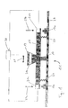
- Fig. 1 shows a switch 11 according to the invention with two switching elements 13a and 13b and a rocker switch 15.
- the rocker switch 15 is rotatably mounted at a pivot point 17 and has an actuating element 19.
- On the rocker switch 15 a plurality of sensors 21 are arranged.
- the sensors 21a and 21b are located above the switching elements 13a and 13b, respectively, and respond to a pushing movement, respectively is shown by arrows 23a and 23b.
- the sensor 21c is mounted on or integrated with the actuator 19 and is responsive to a push / pull movement represented by an arrow 25.
- the switch 11 also has two springs 27 which are attached to the rocker switch 15 and, for example, to a housing wall 29 of the switch.
- the springs 27 press the rocker switch 15 in a neutral position, in which none of the switching elements 13a and 13b is actuated.
- the neutral position is thus defined by means of the springs 27 as the default position of the switch, which is set automatically when no force acts on the switch. This is particularly advantageous when only a short-term actuation of the switching elements 13a and 13b is desired or required.
- a sensor signal is generated by the corresponding sensor and sent to a control unit 30.
- the control unit 30 assigns the sensor signal to one of the switching elements 13a or 13b, activates it and deactivates further switching elements.
- the control unit 30 activates the switching element 13a and deactivates the switching element 13b.
- the sensor 21c determines in which direction the sliding / pulling movement takes place and assigns this movement to the corresponding switching element, for example the switching element 13b, and activates this, while the further switching element 13a is deactivated.
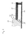
- Fig. 2 shows a particular embodiment of the switch of Fig. 1 , wherein only the left side of the rocker switch 15 is shown by way of example, which is mounted at the pivot point 17.
- the switching rocker 15 has on its left side a locking element 31, which has a spring 33 and a ball 35.
- the ball 35 can engage in recesses 37, which are provided for example in a housing portion 39 of the switch.
- the rocker switch reaches a predetermined position, it can thus be fixed by means of the ball 35 in this position.
- defined switching states and a haptic can be defined, ie the user of the switch 11 can detect the switching states with his sense of touch.
- the recesses 37 are formed differently deep, so that the user of the switch 11 can distinguish by means of the sense of touch between different switching states.
Landscapes
- Push-Button Switches (AREA)
Abstract
Description
- Die vorliegende Erfindung betrifft einen Schalter mit zumindest zwei Schaltelementen, wobei die Schaltelemente sowohl durch eine Drückbewegung als auch durch eine Schiebe-/Zug-Bewegung, die im Wesentlichen senkrecht zu der Drückbewegung orientiert ist, betätigbar sind.
- Derartige Schalter mit mehr als einem Schaltelement, die jeweils verschiedene Schaltfunktionen ausführen, sind in unterschiedlichen Ausführungsformen bekannt und werden beispielsweise als Schalter für Schiebe-und Hebedächer von Kraftfahrzeugen verwendet.
- Üblicherweise weisen derartige Schalter mechanische Betätigungselemente auf. Wenn nur ein einziges mechanisches Betätigungselement verwendet wird, um mehr als ein Schaltelement zu betätigen, muss der Schalter derart konstruiert sein, dass keine Überschneidung der Schaltfunktionen auftritt und keine Fehlfunktion der Schaltelemente erfolgt. Besondere Anforderungen werden an die Konstruktion eines Schalters gestellt, wenn die Schaltelemente des Schalters sowohl durch eine Drückbewegung als auch durch eine Schiebe- / Zug-Bewegung betätigbar sein sollen, wobei diese beiden Arten der Bewegung des Schalters senkrecht zueinander orientiert sind.
- Bei bekannten Schaltern der vorstehend genannten Art werden üblicherweise mechanische Verriegelungselemente verwendet, welche eine Ausführung einer nicht beabsichtigten Schaltfunktion durch eine Mechanik sperren, sobald eine bestimmte Betätigungsrichtung des Schalters, beispielsweise durch eine Drück- oder eine Zieh-/Schiebebewegung, ausgewählt ist.
- Derartige mechanische Verriegelungselemente sind meistens komplex aufgebaut, und daher sind Schalter, die solche rein mechanische Verriegelungselemente verwenden, fehleranfällig und aufwändig herzustellen.
- Es ist daher eine Aufgabe der Erfindung, einen Schalter der eingangs genannten Art zu schaffen, der einfach aufgebaut ist und eine zuverlässige Ausführung einer gewählten Schaltfunktion ohne eine Überschneidung mit weiteren Schaltfunktionen ermöglicht.
- Die Aufgabe wird gelöst durch einen Schalter mit den Merkmalen des Anspruchs 1 und insbesondere dadurch, dass der Schalter mindestens einen ersten elektronischen Sensor aufweist, der auf eine Drückbewegung oder auf eine Schiebe-/Zug-Bewegung anspricht, eine dadurch gewählte Schaltfunktion zulässt und weitere Schaltfunktionen sperrt.
- Da weitere Schaltfunktionen gesperrt sind, wenn der elektronische Sensor auf eine Drückbewegung oder eine Schiebe-/Zug-Bewegung anspricht, benötigt der Schalter keine komplexen mechanischen Verriegelungselemente. Die Verriegelung weiterer, unerwünschter Schaltfunktionen erfolgt stattdessen rein elektronisch. Dadurch ist der mechanische Aufbau des Schalters einfacher und der Betrieb des Schalters zuverlässiger als bei bekannten Schaltern, die mechanische Verriegelungselemente verwenden. Ferner lässt sich der Schalter aufgrund des vereinfachten Aufbaus kostengünstiger herstellen.
- Der Schalter weist vorzugsweise eine Schaltwippe auf, die drehbar gelagert ist. Die mindestens zwei Schaltelemente des Schalters können mittels der Schaltwippe betätigt werden. Da die Schaltwippe zur drehbaren Lagerung nur an einem Punkt befestigt zu werden braucht, erfordert das Anbringen der Schaltwippe nur einen geringen mechanischen Aufwand. Da zwei der Schaltelemente des Schalters vorteilhafterweise auf entgegengesetzten Seiten der Schaltwippe angeordnet sind, wird eine gleichzeitige Betätigung zumindest dieser beiden Schaltelemente durch die Verwendung der Schaltwippe verhindert.
- Die Schaltwippe weist vorteilhafterweise ein Betätigungselement auf, um eine Betätigung der zumindest zwei Schaltelemente durch eine Schiebe-/Zug-Bewegung zu ermöglichen, wobei die Schiebe-/Zug-Bewegung insbesondere durch eine tangential auf das Betätigungselement ausgeübte Kraft ausführbar ist. Das Betätigungselement erleichtert die Bedienung des Schalters und sorgt dafür, dass der Schalter flexibler einsetzbar ist, beispielsweise an unterschiedlichen Orten in einem Kraftfahrzeug. Eine Schiebe-/Zug-Bewegung ist für den Benutzer des Schalters mittels des Betätigungselementes unter Umständen leichter auszuführen als eine Drückbewegung, was von dem Ort abhängt, an dem der Schalter angebracht ist.
- An dem Schalter ist vorzugsweise zumindest eine Feder angeordnet, die mit der Schaltwippe verbunden ist und diese in eine Neutralstellung drückt. Die Neutralstellung ist insbesondere dann erforderlich, wenn mittels des Schalters Schaltfunktionen ausgeführt werden sollen, die einen nur kurzzeitigen Auslösepuls erfordern. Die Neutralstellung, bei dem kein Schaltelement betätigt ist, ist in diesem Fall eine Standardstellung des Schalters.
- Auf der Schaltwippe ist vorteilhafterweise mindestens ein Rastelement angebracht, damit die Schaltwippe mechanisch in einer Ruhelage einrastet. Dadurch wird eine vorteilhafte Haptik für den Benutzer des Schalters geschaffen, d.h. Schaltzustände des Schalters, die durch ein Einrasten der Schaltwippe definierbar sind, können von dem Benutzer des Schalters mittels des Tastsinns wahrgenommen werden. Insbesondere umfasst das Rastelement eine auf einer Feder gelagerte Kugel, die beispielsweise in geeignete Aussparungen eines Schaltergehäuses eingreift, wodurch die Schaltwippe in einer bestimmten Position fixierbar ist.
- Der mindestens eine Sensor des Schalters ist bevorzugt auf der Schaltwippe angeordnet. Durch eine Berührung der Schaltwippe an einer bestimmten Stelle kann der Benutzer des Schalters somit eine bestimmte Schaltfunktion auswählen. Der Sensor bewirkt ferner, dass weitere, nicht erwünschte Schaltfunktionen gesperrt werden.
- Vorteilhafterweise ist der mindestens eine Sensor des Schalters an dem Betätigungselement der Schaltwippe angeordnet, mittels dessen der Schalter durch eine Schiebe-/Zug-Bewegung betätigbar ist. Dabei sind insbesondere zwei alternative Ausführungsformen möglich, die im Folgenden beschrieben sind.
- Gemäß einer Ausführungsform ist der an dem Betätigungselement angeordnete Sensor ausgebildet, um auf die Richtung einer Kraft selektiv anzusprechen, die auf das Betätigungselement ausgeübt wird. Mit anderen Worten kann der Sensor zwischen zwei Richtungen unterscheiden, in die das Betätigungselement der Schaltwippe bewegt wird. Dazu kann der Sensor beispielsweise sensitive Flächen auf entgegengesetzten Seiten des Betätigungselements aufweisen, durch die der Sensor ermitteln kann, welche Seite des Betätigungselements durch den Benutzer des Schalters berührt wird. Wenn der an dem Betätigungselement angeordnete Sensor auf die Richtung der ausgeübten Kraft selektiv anspricht, kann das Betätigungselement in einer einfachen Weise kostengünstig aufgebaut werden, da nur ein Sensor an dem Betätigungselement der Schaltwippe angebracht werden muss.
- Alternativ können zwei Sensoren verwendet werden, die beispielsweise auf entgegengesetzten Seiten des Betätigungselements angebracht sind. Dabei spricht der erste Sensor auf eine Richtung einer auf das Betätigungselement ausgeübten Kraft an, und der zweite Sensor spricht auf eine Kraft an, die auf das Betätigungselement in entgegengesetzter Richtung ausgeübt wird. Werden zwei Sensoren an dem Betätigungselement der Schaltwippe angeordnet, können einfachere und kostengünstigere Sensoren als bei der Ausführungsform mit nur einem Sensor verwendet werden.
- Der Schalter weist vorzugsweise zumindest einen weiteren Sensor auf, wobei der erste Sensor auf die Drückbewegung und der weitere Sensor auf die Schiebe-/Zug-Bewegung anspricht. Dadurch wird der Drückbewegung und der Schiebe-/Zug-Bewegung, die im Wesentlichen senkrecht zueinander orientiert sind und daher zwei unterschiedlichen Betätigungsweisen des Schalters entsprechen, jeweils ein eigener Sensor zugeordnet, wodurch die Zuverlässigkeit des Schalters verbessert wird.
- Vorteilhafterweise ist darüber hinaus jedem Schaltelement jeweils ein eigener Sensor zugeordnet, der auf eine Drückbewegung auf das jeweilige Schaltelement anspricht. Dadurch kann die Betriebssicherheit des Schalters weiter erhöht werden.
- Die Sensoren des Schalters können bevorzugt als kapazitive Sensoren ausgebildet sein. Diese Art der Sensoren ist besonders kostengünstig, insbesondere im Vergleich zu komplexen Verriegelungsmechanismen bekannter Schalter, die mehr als eine Schaltfunktion ausführen.
- Der Schalter umfasst bevorzugt eine Steuereinheit, die mit den Sensoren des Schalters verbunden ist und ausgebildet ist, um Signale der Sensoren auszuwerten. Dabei erfasst die Steuereinheit, ob ein Sensor auf eine Drückbewegung oder auf eine Schiebe-/Zug-Bewegung anspricht, und aktiviert ein Schaltelement, das diesem Sensor zugeordnet ist, wobei weitere Schaltelemente deaktiviert bzw. deren Schaltfunktionen gesperrt werden. Das Deaktivieren bzw. Sperren von unerwünschten Schaltfunktionen wird somit rein elektronisch ausgeführt, indem die Sensoren mit der Steuereinheit zusammenwirken. Zum Sperren bzw. Verriegeln unerwünschter Schaltfunktionen sind somit keine mechanischen Verriegelungselemente erforderlich.
- Weitere bevorzugte Ausführungsformen der Erfindung sind in den Unteransprüchen beschrieben.
- Die Erfindung wird nachfolgend anhand eines Ausführungsbeispiels unter Bezugnahme auf die Zeichnungen erläutert. Es zeigen:
- Fig. 1
- eine Querschnittsansicht eines Schalters,
- Fig. 2
- eine Detailansicht eines Abschnitts des Schalters von
Fig. 1 . -
Fig. 1 zeigt einen erfindungsgemäßen Schalter 11 mit zwei Schaltelementen 13a und 13b sowie einer Schaltwippe 15. Die Schaltwippe 15 ist an einem Drehpunkt 17 drehbar gelagert und weist ein Betätigungselement 19 auf. Auf der Schaltwippe 15 sind mehrere Sensoren 21 angeordnet. Die Sensoren 21a und 21b befinden sich oberhalb der Schaltelemente 13a bzw. 13b und sprechen jeweils auf eine Drückbewegung an, die jeweils durch Pfeile 23a bzw. 23b dargestellt ist. Der Sensor 21c ist an dem Betätigungselement 19 angebracht oder in dieses integriert und spricht auf eine Schiebe-/Zug-Bewegung an, die durch einen Pfeil 25 dargestellt ist. - Der Schalter 11 weist ferner zwei Federn 27 auf, die an der Schaltwippe 15 und beispielsweise an einer Gehäusewand 29 des Schalters befestigt sind. Die Federn 27 drücken die Schaltwippe 15 in eine Neutralstellung, bei der keines der Schaltelemente 13a bzw. 13b betätigt ist. Die Neutralstellung wird somit mittels der Federn 27 als Standardstellung des Schalters definiert, die automatisch eingestellt wird, sobald keine Kraft auf den Schalter wirkt. Dies ist besonders vorteilhaft, wenn eine nur kurzzeitige Betätigung der Schaltelemente 13a bzw. 13b erwünscht bzw. gefordert ist.
- Sobald einer der Sensoren 21 a - c auf eine Drückbewegung oder eine Schiebe-/Zug-Bewegung anspricht, wird ein Sensorsignal von dem entsprechenden Sensor erzeugt und an eine Steuereinheit 30 gesendet. Die Steuereinheit 30 ordnet das Sensorsignal einem der Schaltelemente 13a oder 13b zu, aktiviert dieses und deaktiviert weitere Schaltelemente.
- Wenn beispielsweise eine Drückbewegung, die durch den Pfeil 23a dargestellt ist, auf die Schaltwippe 15 im Bereich des Sensors 21a ausgeübt wird, aktiviert die Steuereinheit 30 das Schaltelement 13a und deaktiviert das Schaltelement 13b. Wird alternativ eine Schiebe-/Zug-Bewegung auf das Betätigungselement 19 der Schaltwippe 15 ausgeübt, so ermittelt der Sensor 21c, in welche Richtung die Schiebe-/Zug-Bewegung erfolgt und ordnet diese Bewegung dem entsprechenden Schaltelement zu, beispielsweise dem Schaltelement 13b, und aktiviert dieses, während das weitere Schaltelement 13a deaktiviert wird.
-
Fig. 2 zeigt eine besondere Ausführungsform des Schalters vonFig. 1 , wobei nur die linke Seite der Schaltwippe 15 beispielhaft dargestellt ist, die an dem Drehpunkt 17 gelagert ist. Die Schaltwippe 15 weist an ihrer linken Seite ein Rastelement 31 auf, das eine Feder 33 und eine Kugel 35 aufweist. Bei einer Bewegung der Schaltwippe 15 kann die Kugel 35 in Aussparungen 37 einrasten, die beispielsweise in einem Gehäuseabschnitt 39 des Schalters vorgesehen sind. Sobald die Schaltwippe eine vorbestimmte Position erreicht, kann sie somit mittels der Kugel 35 in dieser Position fixiert werden. Dadurch können definierte Schaltzustände und eine Haptik definiert werden, d.h. der Benutzer des Schalters 11 kann die Schaltzustände mit seinem Tastsinn erfassen. Insbesondere sind die Aussparungen 37 unterschiedlich tief ausgebildet, damit der Benutzer des Schalters 11 mittels des Tastsinns zwischen verschiedenen Schaltzuständen unterscheiden kann. -
- 11
- Schalter
- 13a, 13b
- Schaltelement
- 15
- Schaltwippe
- 17
- Drehpunkt
- 19
- Betätigungselement
- 21,21a,21b,21c
- Sensor
- 23a,23b
- Pfeil für Drückbewegung
- 25
- Pfeil für Schiebe-/Zug-Bewegung
- 27
- Feder
- 29
- Gehäusewand
- 30
- Steuereinheit
- 31
- Rastelement
- 33
- Feder
- 35
- Kugel
- 37
- Aussparung
- 39
- Gehäuseabschnitt
Claims (15)
- Schalter (11) mit zumindest zwei Schaltelementen (13a, 13b), die sowohl durch eine Drückbewegung (23a, 23b) als auch durch eine im wesentlichen senkrecht dazu orientierte Schiebe-/Zug-Bewegung (25) betätigbar sind, und mit mindestens einem ersten elektronischen Sensor (21), der auf die Drückbewegung (23a, 23b) oder auf die Schiebe-/Zug-Bewegung (25) anspricht, eine dadurch gewählte Schaltfunktion zulässt und weitere Schaltfunktionen sperrt.
- Schalter nach Anspruch 1,
dadurch gekennzeichnet, dass
der Schalter (11) eine Schaltwippe (15) aufweist, die drehbar gelagert ist und mittels derer die mindestens zwei Schaltelemente (13a, 13b) betätigbar sind. - Schalter nach Anspruch 2,
dadurch gekennzeichnet, dass
die Schaltwippe (15) ein Betätigungselement (19) für die Schiebe-/Zug-Bewegung (25) aufweist. - Schalter nach Anspruch 3,
dadurch gekennzeichnet, dass
die Schiebe-/Zug-Bewegung (25) durch eine tangential auf das Betätigungselement (19) ausgeübte Kraft ausführbar ist. - Schalter zumindest einem der Ansprüche 2 bis 4,
dadurch gekennzeichnet, dass
die Schaltwippe (15) durch zumindest eine Feder (27) in eine Neutralstellung gedrückt wird. - Schalter nach zumindest einem der Ansprüche 2 bis 5,
dadurch gekennzeichnet, dass
die Schaltwippe (15) mindestens ein Rastelement (31) aufweist, um die Schaltwippe (15) mechanisch in einer Ruhelage einzurasten. - Schalter nach Anspruch 6,
dadurch gekennzeichnet, dass
das Rastelement (31) eine auf einer Feder (33) gelagerte Kugel (35) aufweist. - Schalter nach zumindest einem der Ansprüche 2 bis 7,
dadurch gekennzeichnet, dass
der Sensor (21) auf der Schaltwippe (15) angeordnet ist. - Schalter nach zumindest einem der Ansprüche 3 bis 8,
dadurch gekennzeichnet, dass
der Sensor (21) an dem Betätigungselement (19) der Schaltwippe (15) angeordnet ist. - Schalter nach Anspruch 9,
dadurch gekennzeichnet, dass
der an dem Betätigungselement (19) angeordnete Sensor (21) auf die Richtung einer auf das Betätigungselement (19) ausgeübten Kraft selektiv anspricht. - Schalter nach Anspruch 9,
dadurch gekennzeichnet, dass
ein zweiter Sensor (21) an dem Betätigungselement (19) angeordnet ist, wobei der erste Sensor (21) auf eine Richtung einer auf das Betätigungselement (19) ausgeübten Kraft und der zweite Sensor (21) auf eine entgegengesetzte Richtung einer auf das Betätigungselement (19) ausgeübten Kraft anspricht. - Schalter nach zumindest einem der vorstehenden Ansprüche,
dadurch gekennzeichnet, dass
dieser zumindest einen weiteren Sensor (2 1 c) aufweist, wobei der erste Sensor (21a, 21b) auf die Drückbewegung (23a, 23b) und der weitere Sensor (21c) auf die Schiebe- / Zug-Bewegung (25) anspricht. - Schalter nach zumindest einem der vorstehenden Ansprüche,
dadurch gekennzeichnet, dass
jedem Schaltelement (13a, 13b) jeweils ein Sensor (21a, 21b) zugeordnet ist, der auf eine Drückbewegung (23a, 23b) in Richtung auf das jeweilige Schaltelement (13a, 13b) anspricht. - Schalter nach zumindest einem der vorstehenden Ansprüche,
dadurch gekennzeichnet, dass
der Schalter (11) eine Steuereinheit (30) aufweist, die auswertet, ob ein Sensor (21) auf eine Drückbewegung (23a, 23b) oder auf eine Schiebe- / Zug-Bewegung (25) anspricht, und ein dem Sensor (21) zugeordnetes Schaltelement (13a, 13b) aktiviert sowie weitere Schaltelemente (13a, 13b) deaktiviert. - Schalter nach zumindest einem der vorstehenden Ansprüche,
dadurch gekennzeichnet, dass
die Sensoren (21a, 21b, 21c) als kapazitive Sensoren ausgebildet sind.
Priority Applications (1)
| Application Number | Priority Date | Filing Date | Title |
|---|---|---|---|
| EP20080017964 EP2178098B1 (de) | 2008-10-14 | 2008-10-14 | Schalter |
Applications Claiming Priority (1)
| Application Number | Priority Date | Filing Date | Title |
|---|---|---|---|
| EP20080017964 EP2178098B1 (de) | 2008-10-14 | 2008-10-14 | Schalter |
Publications (2)
| Publication Number | Publication Date |
|---|---|
| EP2178098A1 true EP2178098A1 (de) | 2010-04-21 |
| EP2178098B1 EP2178098B1 (de) | 2012-05-30 |
Family
ID=40383894
Family Applications (1)
| Application Number | Title | Priority Date | Filing Date |
|---|---|---|---|
| EP20080017964 Active EP2178098B1 (de) | 2008-10-14 | 2008-10-14 | Schalter |
Country Status (1)
| Country | Link |
|---|---|
| EP (1) | EP2178098B1 (de) |
Cited By (3)
| Publication number | Priority date | Publication date | Assignee | Title |
|---|---|---|---|---|
| DE102010042524A1 (de) * | 2010-10-15 | 2012-04-19 | Siemens Aktiengesellschaft | Tragbares Gerät mit Bedieneinheit |
| ITBZ20120005A1 (it) * | 2012-02-10 | 2013-08-11 | Alpgate S R L | Interruttore a bilico |
| DE102016118459A1 (de) | 2016-09-29 | 2018-03-29 | Jungheinrich Aktiengesellschaft | Flurförderzeug mit einem einen Bedienhebel aufweisenden Bedienmittel sowie Verfahren zur Bedienung eines solchen Flurförderzeugs |
Citations (3)
| Publication number | Priority date | Publication date | Assignee | Title |
|---|---|---|---|---|
| DE20103570U1 (de) * | 2001-02-23 | 2001-05-03 | Ludwig, Manfred, Dipl.-Phys. Dr., 07743 Jena | Einzeltaste mit Druckschalter zur Fehlbedienungssicherung |
| DE10027484C1 (de) * | 2000-06-02 | 2001-12-20 | Kostal Leopold Gmbh & Co Kg | Kipp-Schiebe-Schalter |
| DE102005005185A1 (de) * | 2005-02-03 | 2006-08-17 | Daimlerchrysler Ag | Schaltanordnung für ein Schaltelement zum Öffnen und Schließen eines Fahrzeugflügels |
-
2008
- 2008-10-14 EP EP20080017964 patent/EP2178098B1/de active Active
Patent Citations (3)
| Publication number | Priority date | Publication date | Assignee | Title |
|---|---|---|---|---|
| DE10027484C1 (de) * | 2000-06-02 | 2001-12-20 | Kostal Leopold Gmbh & Co Kg | Kipp-Schiebe-Schalter |
| DE20103570U1 (de) * | 2001-02-23 | 2001-05-03 | Ludwig, Manfred, Dipl.-Phys. Dr., 07743 Jena | Einzeltaste mit Druckschalter zur Fehlbedienungssicherung |
| DE102005005185A1 (de) * | 2005-02-03 | 2006-08-17 | Daimlerchrysler Ag | Schaltanordnung für ein Schaltelement zum Öffnen und Schließen eines Fahrzeugflügels |
Cited By (6)
| Publication number | Priority date | Publication date | Assignee | Title |
|---|---|---|---|---|
| DE102010042524A1 (de) * | 2010-10-15 | 2012-04-19 | Siemens Aktiengesellschaft | Tragbares Gerät mit Bedieneinheit |
| DE102010042524B4 (de) * | 2010-10-15 | 2012-08-02 | Siemens Aktiengesellschaft | Tragbares Gerät mit Bedieneinheit |
| US9824833B2 (en) | 2010-10-15 | 2017-11-21 | Siemens Aktiengesellschaft | Appliance comprising an operating unit |
| ITBZ20120005A1 (it) * | 2012-02-10 | 2013-08-11 | Alpgate S R L | Interruttore a bilico |
| DE102016118459A1 (de) | 2016-09-29 | 2018-03-29 | Jungheinrich Aktiengesellschaft | Flurförderzeug mit einem einen Bedienhebel aufweisenden Bedienmittel sowie Verfahren zur Bedienung eines solchen Flurförderzeugs |
| US10664003B2 (en) | 2016-09-29 | 2020-05-26 | Jungheinrich Aktiengesellschaft | Industrial truck with operating assembly and associated method |
Also Published As
| Publication number | Publication date |
|---|---|
| EP2178098B1 (de) | 2012-05-30 |
Similar Documents
| Publication | Publication Date | Title |
|---|---|---|
| EP3739155B1 (de) | Türgriffanordnung | |
| EP1512814B1 (de) | Kraftfahrzeug-Türschliesssystem und Türgriff | |
| EP2333208B1 (de) | Kraftfahrzeugschloss | |
| DE102010024776B4 (de) | Vorrichtung zur Bedienung mehrerer Funktionen in einem Kraftfahrzeug | |
| EP4258312A2 (de) | Türentriegelungs- und/oder türöffnungsmechanismus mit einer betätigungsvorrichtung | |
| DE102018204351A1 (de) | Türverriegelungseinrichtung für ein Kraftfahrzeug | |
| EP2178098B1 (de) | Schalter | |
| EP2647126B1 (de) | Bedieneinheit mit kapazitivem berührungssensor | |
| DE102007024874A1 (de) | Betätigungselement einer Fahrzeug-Benutzer-Schnittstelle | |
| DE102012019387A1 (de) | Druck- und drehbetätigbares Bedienelement für ein Kraftfahrzeug | |
| DE102009053717B4 (de) | Anordnung mit einem Sicherheitsschalter oder einer Sicherheitszuhaltung und einem mechanischen Betätiger | |
| EP3149263A1 (de) | Türgriff für ein kraftfahrzeug | |
| EP1758135B1 (de) | Schaltereinheit | |
| DE102017107401A1 (de) | Bedienanordnung zum Bedienen von zumindest einem elektrischen Gerät mit einem Kraftsensor, Fahrerassistenzsystem, Kraftfahrzeug sowie Verfahren zum Bedienen einer Bedienanordnung | |
| DE102022131902A1 (de) | Verfahren zur bereitstellung eines aktivhaptischen rückmeldungssignals für ein bedienelement | |
| DE10312226B4 (de) | Taste für sicherheitsgerichtete Schaltprozesse | |
| DE102014017906A1 (de) | Lenkrad mit Wechselschalter | |
| DE102013004381A1 (de) | Eingabeeinheit für ein druck- und drehbetätigbares Bedienelement | |
| DE102009008537B3 (de) | Drucktaster | |
| DE102011082142A1 (de) | Bedieneinrichtung | |
| DE102024104567A1 (de) | Druck- und drehbetätigbares Bedienelement für ein Kraftfahrzeug | |
| DE102023121030A1 (de) | Kraftfahrzeug-Schloss insbesondere Kraftfahrzeug-Türschloss | |
| DE102024116829A1 (de) | Bedieneinheit für ein Kraftfahrzeug und Verfahren zum Steuern einer Bedieneinheit | |
| DE102021207689A1 (de) | Einrichtung zum Öffnen einer Fahrzeugtür und Fahrzeug mit einer solchen Einrichtung | |
| DE102023132524A1 (de) | Betätigungsmechanismus zum betätigen von fahrzeugtüren |
Legal Events
| Date | Code | Title | Description |
|---|---|---|---|
| PUAI | Public reference made under article 153(3) epc to a published international application that has entered the european phase |
Free format text: ORIGINAL CODE: 0009012 |
|
| AK | Designated contracting states |
Kind code of ref document: A1 Designated state(s): AT BE BG CH CY CZ DE DK EE ES FI FR GB GR HR HU IE IS IT LI LT LU LV MC MT NL NO PL PT RO SE SI SK TR |
|
| AX | Request for extension of the european patent |
Extension state: AL BA MK RS |
|
| 17P | Request for examination filed |
Effective date: 20100615 |
|
| AKX | Designation fees paid |
Designated state(s): AT BE BG CH CY CZ DE DK EE ES FI FR GB GR HR HU IE IS IT LI LT LU LV MC MT NL NO PL PT RO SE SI SK TR |
|
| GRAP | Despatch of communication of intention to grant a patent |
Free format text: ORIGINAL CODE: EPIDOSNIGR1 |
|
| GRAS | Grant fee paid |
Free format text: ORIGINAL CODE: EPIDOSNIGR3 |
|
| GRAA | (expected) grant |
Free format text: ORIGINAL CODE: 0009210 |
|
| AK | Designated contracting states |
Kind code of ref document: B1 Designated state(s): AT BE BG CH CY CZ DE DK EE ES FI FR GB GR HR HU IE IS IT LI LT LU LV MC MT NL NO PL PT RO SE SI SK TR |
|
| REG | Reference to a national code |
Ref country code: GB Ref legal event code: FG4D Free format text: NOT ENGLISH |
|
| REG | Reference to a national code |
Ref country code: CH Ref legal event code: EP |
|
| REG | Reference to a national code |
Ref country code: AT Ref legal event code: REF Ref document number: 560399 Country of ref document: AT Kind code of ref document: T Effective date: 20120615 |
|
| REG | Reference to a national code |
Ref country code: IE Ref legal event code: FG4D Free format text: LANGUAGE OF EP DOCUMENT: GERMAN |
|
| REG | Reference to a national code |
Ref country code: DE Ref legal event code: R096 Ref document number: 502008007294 Country of ref document: DE Effective date: 20120802 |
|
| REG | Reference to a national code |
Ref country code: NL Ref legal event code: VDEP Effective date: 20120530 |
|
| REG | Reference to a national code |
Ref country code: LT Ref legal event code: MG4D Effective date: 20120530 |
|
| PG25 | Lapsed in a contracting state [announced via postgrant information from national office to epo] |
Ref country code: CY Free format text: LAPSE BECAUSE OF FAILURE TO SUBMIT A TRANSLATION OF THE DESCRIPTION OR TO PAY THE FEE WITHIN THE PRESCRIBED TIME-LIMIT Effective date: 20120530 Ref country code: NO Free format text: LAPSE BECAUSE OF FAILURE TO SUBMIT A TRANSLATION OF THE DESCRIPTION OR TO PAY THE FEE WITHIN THE PRESCRIBED TIME-LIMIT Effective date: 20120830 Ref country code: SE Free format text: LAPSE BECAUSE OF FAILURE TO SUBMIT A TRANSLATION OF THE DESCRIPTION OR TO PAY THE FEE WITHIN THE PRESCRIBED TIME-LIMIT Effective date: 20120530 Ref country code: LT Free format text: LAPSE BECAUSE OF FAILURE TO SUBMIT A TRANSLATION OF THE DESCRIPTION OR TO PAY THE FEE WITHIN THE PRESCRIBED TIME-LIMIT Effective date: 20120530 Ref country code: IS Free format text: LAPSE BECAUSE OF FAILURE TO SUBMIT A TRANSLATION OF THE DESCRIPTION OR TO PAY THE FEE WITHIN THE PRESCRIBED TIME-LIMIT Effective date: 20120930 Ref country code: FI Free format text: LAPSE BECAUSE OF FAILURE TO SUBMIT A TRANSLATION OF THE DESCRIPTION OR TO PAY THE FEE WITHIN THE PRESCRIBED TIME-LIMIT Effective date: 20120530 |
|
| PG25 | Lapsed in a contracting state [announced via postgrant information from national office to epo] |
Ref country code: SI Free format text: LAPSE BECAUSE OF FAILURE TO SUBMIT A TRANSLATION OF THE DESCRIPTION OR TO PAY THE FEE WITHIN THE PRESCRIBED TIME-LIMIT Effective date: 20120530 Ref country code: LV Free format text: LAPSE BECAUSE OF FAILURE TO SUBMIT A TRANSLATION OF THE DESCRIPTION OR TO PAY THE FEE WITHIN THE PRESCRIBED TIME-LIMIT Effective date: 20120530 Ref country code: HR Free format text: LAPSE BECAUSE OF FAILURE TO SUBMIT A TRANSLATION OF THE DESCRIPTION OR TO PAY THE FEE WITHIN THE PRESCRIBED TIME-LIMIT Effective date: 20120530 Ref country code: GR Free format text: LAPSE BECAUSE OF FAILURE TO SUBMIT A TRANSLATION OF THE DESCRIPTION OR TO PAY THE FEE WITHIN THE PRESCRIBED TIME-LIMIT Effective date: 20120831 |
|
| PG25 | Lapsed in a contracting state [announced via postgrant information from national office to epo] |
Ref country code: SK Free format text: LAPSE BECAUSE OF FAILURE TO SUBMIT A TRANSLATION OF THE DESCRIPTION OR TO PAY THE FEE WITHIN THE PRESCRIBED TIME-LIMIT Effective date: 20120530 Ref country code: CZ Free format text: LAPSE BECAUSE OF FAILURE TO SUBMIT A TRANSLATION OF THE DESCRIPTION OR TO PAY THE FEE WITHIN THE PRESCRIBED TIME-LIMIT Effective date: 20120530 Ref country code: NL Free format text: LAPSE BECAUSE OF FAILURE TO SUBMIT A TRANSLATION OF THE DESCRIPTION OR TO PAY THE FEE WITHIN THE PRESCRIBED TIME-LIMIT Effective date: 20120530 Ref country code: EE Free format text: LAPSE BECAUSE OF FAILURE TO SUBMIT A TRANSLATION OF THE DESCRIPTION OR TO PAY THE FEE WITHIN THE PRESCRIBED TIME-LIMIT Effective date: 20120530 Ref country code: RO Free format text: LAPSE BECAUSE OF FAILURE TO SUBMIT A TRANSLATION OF THE DESCRIPTION OR TO PAY THE FEE WITHIN THE PRESCRIBED TIME-LIMIT Effective date: 20120530 Ref country code: DK Free format text: LAPSE BECAUSE OF FAILURE TO SUBMIT A TRANSLATION OF THE DESCRIPTION OR TO PAY THE FEE WITHIN THE PRESCRIBED TIME-LIMIT Effective date: 20120530 |
|
| PG25 | Lapsed in a contracting state [announced via postgrant information from national office to epo] |
Ref country code: PT Free format text: LAPSE BECAUSE OF FAILURE TO SUBMIT A TRANSLATION OF THE DESCRIPTION OR TO PAY THE FEE WITHIN THE PRESCRIBED TIME-LIMIT Effective date: 20121001 Ref country code: PL Free format text: LAPSE BECAUSE OF FAILURE TO SUBMIT A TRANSLATION OF THE DESCRIPTION OR TO PAY THE FEE WITHIN THE PRESCRIBED TIME-LIMIT Effective date: 20120530 |
|
| PLBE | No opposition filed within time limit |
Free format text: ORIGINAL CODE: 0009261 |
|
| STAA | Information on the status of an ep patent application or granted ep patent |
Free format text: STATUS: NO OPPOSITION FILED WITHIN TIME LIMIT |
|
| BERE | Be: lapsed |
Owner name: DELPHI TECHNOLOGIES, INC. Effective date: 20121031 |
|
| PG25 | Lapsed in a contracting state [announced via postgrant information from national office to epo] |
Ref country code: ES Free format text: LAPSE BECAUSE OF FAILURE TO SUBMIT A TRANSLATION OF THE DESCRIPTION OR TO PAY THE FEE WITHIN THE PRESCRIBED TIME-LIMIT Effective date: 20120910 |
|
| 26N | No opposition filed |
Effective date: 20130301 |
|
| PG25 | Lapsed in a contracting state [announced via postgrant information from national office to epo] |
Ref country code: MC Free format text: LAPSE BECAUSE OF NON-PAYMENT OF DUE FEES Effective date: 20121031 |
|
| REG | Reference to a national code |
Ref country code: CH Ref legal event code: PL |
|
| GBPC | Gb: european patent ceased through non-payment of renewal fee |
Effective date: 20121014 |
|
| REG | Reference to a national code |
Ref country code: DE Ref legal event code: R097 Ref document number: 502008007294 Country of ref document: DE Effective date: 20130301 |
|
| REG | Reference to a national code |
Ref country code: IE Ref legal event code: MM4A |
|
| PG25 | Lapsed in a contracting state [announced via postgrant information from national office to epo] |
Ref country code: GB Free format text: LAPSE BECAUSE OF NON-PAYMENT OF DUE FEES Effective date: 20121014 Ref country code: CH Free format text: LAPSE BECAUSE OF NON-PAYMENT OF DUE FEES Effective date: 20121031 Ref country code: LI Free format text: LAPSE BECAUSE OF NON-PAYMENT OF DUE FEES Effective date: 20121031 Ref country code: BE Free format text: LAPSE BECAUSE OF NON-PAYMENT OF DUE FEES Effective date: 20121031 Ref country code: IE Free format text: LAPSE BECAUSE OF NON-PAYMENT OF DUE FEES Effective date: 20121014 Ref country code: BG Free format text: LAPSE BECAUSE OF FAILURE TO SUBMIT A TRANSLATION OF THE DESCRIPTION OR TO PAY THE FEE WITHIN THE PRESCRIBED TIME-LIMIT Effective date: 20120830 |
|
| PG25 | Lapsed in a contracting state [announced via postgrant information from national office to epo] |
Ref country code: MT Free format text: LAPSE BECAUSE OF FAILURE TO SUBMIT A TRANSLATION OF THE DESCRIPTION OR TO PAY THE FEE WITHIN THE PRESCRIBED TIME-LIMIT Effective date: 20120530 |
|
| REG | Reference to a national code |
Ref country code: FR Ref legal event code: TP Owner name: DELPHI INTERNATIONAL OPERATIONS LUXEMBOURG S.A, LU Effective date: 20131218 |
|
| PG25 | Lapsed in a contracting state [announced via postgrant information from national office to epo] |
Ref country code: TR Free format text: LAPSE BECAUSE OF FAILURE TO SUBMIT A TRANSLATION OF THE DESCRIPTION OR TO PAY THE FEE WITHIN THE PRESCRIBED TIME-LIMIT Effective date: 20120530 |
|
| PG25 | Lapsed in a contracting state [announced via postgrant information from national office to epo] |
Ref country code: LU Free format text: LAPSE BECAUSE OF NON-PAYMENT OF DUE FEES Effective date: 20121014 |
|
| PG25 | Lapsed in a contracting state [announced via postgrant information from national office to epo] |
Ref country code: HU Free format text: LAPSE BECAUSE OF FAILURE TO SUBMIT A TRANSLATION OF THE DESCRIPTION OR TO PAY THE FEE WITHIN THE PRESCRIBED TIME-LIMIT Effective date: 20081014 |
|
| REG | Reference to a national code |
Ref country code: AT Ref legal event code: MM01 Ref document number: 560399 Country of ref document: AT Kind code of ref document: T Effective date: 20131014 |
|
| PG25 | Lapsed in a contracting state [announced via postgrant information from national office to epo] |
Ref country code: AT Free format text: LAPSE BECAUSE OF NON-PAYMENT OF DUE FEES Effective date: 20131014 |
|
| REG | Reference to a national code |
Ref country code: FR Ref legal event code: PLFP Year of fee payment: 8 |
|
| REG | Reference to a national code |
Ref country code: FR Ref legal event code: PLFP Year of fee payment: 9 |
|
| REG | Reference to a national code |
Ref country code: FR Ref legal event code: PLFP Year of fee payment: 10 |
|
| REG | Reference to a national code |
Ref country code: FR Ref legal event code: PLFP Year of fee payment: 11 |
|
| REG | Reference to a national code |
Ref country code: DE Ref legal event code: R081 Ref document number: 502008007294 Country of ref document: DE Owner name: APTIV TECHNOLOGIES LIMITED, BB Free format text: FORMER OWNER: DELPHI TECHNOLOGIES, INC., TROY, MICH., US |
|
| PGFP | Annual fee paid to national office [announced via postgrant information from national office to epo] |
Ref country code: IT Payment date: 20191023 Year of fee payment: 12 Ref country code: FR Payment date: 20191025 Year of fee payment: 12 |
|
| PG25 | Lapsed in a contracting state [announced via postgrant information from national office to epo] |
Ref country code: FR Free format text: LAPSE BECAUSE OF NON-PAYMENT OF DUE FEES Effective date: 20201031 |
|
| PG25 | Lapsed in a contracting state [announced via postgrant information from national office to epo] |
Ref country code: IT Free format text: LAPSE BECAUSE OF NON-PAYMENT OF DUE FEES Effective date: 20201014 |
|
| P01 | Opt-out of the competence of the unified patent court (upc) registered |
Effective date: 20230425 |
|
| PGFP | Annual fee paid to national office [announced via postgrant information from national office to epo] |
Ref country code: DE Payment date: 20240925 Year of fee payment: 17 |
|
| REG | Reference to a national code |
Ref country code: DE Ref legal event code: R081 Ref document number: 502008007294 Country of ref document: DE Owner name: APTIV TECHNOLOGIES AG, CH Free format text: FORMER OWNER: APTIV TECHNOLOGIES LIMITED, ST. MICHAEL, BB |