EP2178144A1 - Cellule d'électrolyse ou de combustible et utilisation de la cellule d'électrolyse ou de combustible - Google Patents
Cellule d'électrolyse ou de combustible et utilisation de la cellule d'électrolyse ou de combustible Download PDFInfo
- Publication number
- EP2178144A1 EP2178144A1 EP09172385A EP09172385A EP2178144A1 EP 2178144 A1 EP2178144 A1 EP 2178144A1 EP 09172385 A EP09172385 A EP 09172385A EP 09172385 A EP09172385 A EP 09172385A EP 2178144 A1 EP2178144 A1 EP 2178144A1
- Authority
- EP
- European Patent Office
- Prior art keywords
- cathode
- electrolysis
- anode
- fuel cell
- membrane
- Prior art date
- Legal status (The legal status is an assumption and is not a legal conclusion. Google has not performed a legal analysis and makes no representation as to the accuracy of the status listed.)
- Withdrawn
Links
Images



Classifications
-
- H—ELECTRICITY
- H01—ELECTRIC ELEMENTS
- H01M—PROCESSES OR MEANS, e.g. BATTERIES, FOR THE DIRECT CONVERSION OF CHEMICAL ENERGY INTO ELECTRICAL ENERGY
- H01M8/00—Fuel cells; Manufacture thereof
- H01M8/02—Details
- H01M8/0202—Collectors; Separators, e.g. bipolar separators; Interconnectors
- H01M8/023—Porous and characterised by the material
- H01M8/0232—Metals or alloys
-
- C—CHEMISTRY; METALLURGY
- C25—ELECTROLYTIC OR ELECTROPHORETIC PROCESSES; APPARATUS THEREFOR
- C25B—ELECTROLYTIC OR ELECTROPHORETIC PROCESSES FOR THE PRODUCTION OF COMPOUNDS OR NON-METALS; APPARATUS THEREFOR
- C25B1/00—Electrolytic production of inorganic compounds or non-metals
- C25B1/01—Products
- C25B1/02—Hydrogen or oxygen
- C25B1/04—Hydrogen or oxygen by electrolysis of water
-
- C—CHEMISTRY; METALLURGY
- C25—ELECTROLYTIC OR ELECTROPHORETIC PROCESSES; APPARATUS THEREFOR
- C25B—ELECTROLYTIC OR ELECTROPHORETIC PROCESSES FOR THE PRODUCTION OF COMPOUNDS OR NON-METALS; APPARATUS THEREFOR
- C25B9/00—Cells or assemblies of cells; Constructional parts of cells; Assemblies of constructional parts, e.g. electrode-diaphragm assemblies; Process-related cell features
- C25B9/17—Cells comprising dimensionally-stable non-movable electrodes; Assemblies of constructional parts thereof
- C25B9/19—Cells comprising dimensionally-stable non-movable electrodes; Assemblies of constructional parts thereof with diaphragms
- C25B9/23—Cells comprising dimensionally-stable non-movable electrodes; Assemblies of constructional parts thereof with diaphragms comprising ion-exchange membranes in or on which electrode material is embedded
-
- H—ELECTRICITY
- H01—ELECTRIC ELEMENTS
- H01M—PROCESSES OR MEANS, e.g. BATTERIES, FOR THE DIRECT CONVERSION OF CHEMICAL ENERGY INTO ELECTRICAL ENERGY
- H01M8/00—Fuel cells; Manufacture thereof
- H01M8/02—Details
- H01M8/0271—Sealing or supporting means around electrodes, matrices or membranes
-
- H—ELECTRICITY
- H01—ELECTRIC ELEMENTS
- H01M—PROCESSES OR MEANS, e.g. BATTERIES, FOR THE DIRECT CONVERSION OF CHEMICAL ENERGY INTO ELECTRICAL ENERGY
- H01M8/00—Fuel cells; Manufacture thereof
- H01M8/10—Fuel cells with solid electrolytes
- H01M8/1007—Fuel cells with solid electrolytes with both reactants being gaseous or vaporised
-
- H—ELECTRICITY
- H01—ELECTRIC ELEMENTS
- H01M—PROCESSES OR MEANS, e.g. BATTERIES, FOR THE DIRECT CONVERSION OF CHEMICAL ENERGY INTO ELECTRICAL ENERGY
- H01M8/00—Fuel cells; Manufacture thereof
- H01M8/18—Regenerative fuel cells, e.g. redox flow batteries or secondary fuel cells
- H01M8/184—Regeneration by electrochemical means
-
- H—ELECTRICITY
- H01—ELECTRIC ELEMENTS
- H01M—PROCESSES OR MEANS, e.g. BATTERIES, FOR THE DIRECT CONVERSION OF CHEMICAL ENERGY INTO ELECTRICAL ENERGY
- H01M4/00—Electrodes
- H01M4/86—Inert electrodes with catalytic activity, e.g. for fuel cells
-
- Y—GENERAL TAGGING OF NEW TECHNOLOGICAL DEVELOPMENTS; GENERAL TAGGING OF CROSS-SECTIONAL TECHNOLOGIES SPANNING OVER SEVERAL SECTIONS OF THE IPC; TECHNICAL SUBJECTS COVERED BY FORMER USPC CROSS-REFERENCE ART COLLECTIONS [XRACs] AND DIGESTS
- Y02—TECHNOLOGIES OR APPLICATIONS FOR MITIGATION OR ADAPTATION AGAINST CLIMATE CHANGE
- Y02E—REDUCTION OF GREENHOUSE GAS [GHG] EMISSIONS, RELATED TO ENERGY GENERATION, TRANSMISSION OR DISTRIBUTION
- Y02E60/00—Enabling technologies; Technologies with a potential or indirect contribution to GHG emissions mitigation
- Y02E60/30—Hydrogen technology
- Y02E60/36—Hydrogen production from non-carbon containing sources, e.g. by water electrolysis
-
- Y—GENERAL TAGGING OF NEW TECHNOLOGICAL DEVELOPMENTS; GENERAL TAGGING OF CROSS-SECTIONAL TECHNOLOGIES SPANNING OVER SEVERAL SECTIONS OF THE IPC; TECHNICAL SUBJECTS COVERED BY FORMER USPC CROSS-REFERENCE ART COLLECTIONS [XRACs] AND DIGESTS
- Y02—TECHNOLOGIES OR APPLICATIONS FOR MITIGATION OR ADAPTATION AGAINST CLIMATE CHANGE
- Y02E—REDUCTION OF GREENHOUSE GAS [GHG] EMISSIONS, RELATED TO ENERGY GENERATION, TRANSMISSION OR DISTRIBUTION
- Y02E60/00—Enabling technologies; Technologies with a potential or indirect contribution to GHG emissions mitigation
- Y02E60/30—Hydrogen technology
- Y02E60/50—Fuel cells
Definitions
- the invention relates to an electrolysis or fuel cell according to the preamble of claim 1 and a use of electrolysis or fuel cell according to the preamble of claim 12 or 13th
- Hydrogen is a chemical element that is hardly found in nature in pure form, but in large quantities in compounds, especially naturally in water, ie in H 2 O. Hydrogen is therefore generally obtained from water, for which various Methods are known.
- hydrogen-generating devices which are sometimes referred to as hydrogen generators used.
- the hydrogen can be obtained from water according to the principle of electrolysis, that is according to formula (1).
- the resulting oxygen generally escapes into the environment.
- Such hydrogen-generating devices have as a central unit an electrolysis cell in which the actual chemical / physical reaction takes place, which is described by the above-mentioned formula (1).
- this reaction can occur not only in a direction in which hydrogen is generated by electrolysis, but alternatively in the opposite direction. If the reaction proceeds in the opposite direction, no electrolysis takes place.
- the cell conventionally referred to as an electrolysis cell in the present specification has also been referred to as an electrolysis cell or, more simply, as a cell.
- the reaction takes place as electrolysis, whereby water is decomposed into hydrogen and oxygen, then this is a reaction which can proceed only with the expenditure of energy, in the present case with the expenditure of electrical energy.
- a voltage must be applied to supply the required energy.
- the cell acts as an electrolysis cell or as a hydrogen generator.
- reaction proceeds in the opposite direction, whereby water is formed from hydrogen and oxygen, then this is a reaction that proceeds with the release of energy, in the present case with the release of electrical energy. So if the cell is charged with oxygen and hydrogen, so oxygen and hydrogen combine and at the electrodes of the cell, a voltage can be tapped. In this case, the cell acts as a fuel cell.
- Electrolysis cells are known having a structure and a mode of operation which will be described below with reference to electrolysis of water by consuming electrical energy, although, as just mentioned, such cells are also used for the synthesis of water with simultaneous delivery of electrical energy can.
- a conventional electrolysis cell has, as usual, a housing of a plurality of housing parts, optionally covered with sealing films, on, further two electrodes, namely a positive anode and a negative cathode.
- the electrodes are plate-shaped and on each electrode, on the surface facing the opposite electrode, a plurality of mutually adjacent or interconnected grid or honeycomb formed networks arranged. These networks form a structure with cavities. These cavities form a manifold branched flow channel; wherein the resulting capillary action guarantees fluid distribution over the entire area.
- the fluids involved consist of water as the starting material, hydrogen as the product to be produced and oxygen to some extent as a waste product. However, generally not all of the water supplied is decomposed into hydrogen and oxygen so that the product may consist of a hydrogen / water mixture and the waste product of an oxygen / water mixture.
- a coated membrane is arranged, which is permeable to hydrogen molecules H 2 and water molecules H 2 O, for oxygen molecules O 2 but impermeable. Due to the voltage applied between the cathode and the anode, part of the water is decomposed into hydrogen and oxygen while the rest of the water is not decomposed.
- the fluids involved flow through the cavities of the grid or honeycomb networks.
- water and emerging oxygen flow through the cavities of the grid or honeycomb networks on the side facing the anode membrane.
- water penetrates through the membrane onto the side of the membrane facing the cathode, as does hydrogen produced at the membrane. Residual water and the resulting hydrogen then flow through the cavities of the lattice or honeycomb networks on the membrane side facing the cathode.
- the oxygen and residual water leave the space between the anode and the membrane at an oxygen / water port, while the hydrogen and other residual water leave the space between the cathode and the membrane at a hydrogen / water port. If the hydrogen H 2 is fed into a closed system, then a pressure can build up.
- the electrolysis cell described above has many disadvantages, the most important of which are described below.
- the membrane is provided under the prevailing pressure in the cavities with a structure, or pressed into the lattice or honeycomb-like networks and by the boundary of the cavities or the lattice or honeycomb-like Structure is damaged, with the result that the electrolysis can not proceed as intended.
- the structure of the electrolysis cell is relatively complicated and therefore expensive, since it has a variety of components, namely the previously not mentioned housing with the connections for the water inlet, the oxygen outlet and the hydrogen / water outlet, the Anode, the cathode and the membrane.
- the numerous components have the consequence that within the electrolysis cell, a plurality of contact points is or should be present, which is manufacturing technology and functionally unfavorable.
- the life of the electrolysis cell is relatively low, because the most vulnerable component, namely the membrane, can not be replaced.
- a replacement of the membrane would be cumbersome due to the numerous components of the electrolysis cell anyway and is therefore impossible, because not only rubber or plastic sealing body but also silicone compound is used to produce the necessary absolute tightness of the housing, which in disassembly the individual components in leaves such a polluted state that their further use is practically out of the question.
- electrolysis or fuel cell of the company Schmidlin Labor + Service AG, Switzerland, which is offered under the name of electrolysis cell.
- This electrolysis or fuel cell has eliminated a large part of the disadvantages mentioned and has therefore proved very successful.
- This electrolysis or fuel cell is in the published European patent application EP 1 077 499 described.
- the corresponding electrolysis or fuel cell has only a few components, namely two disc-like housing parts, two electrodes with active surfaces and a coated membrane, and a few sealing body. However, no sealing compounds and no grid or honeycomb networks are needed as a structure.
- the active surfaces of the anode and the cathode are directly adjacent to the coated membrane, and the structure forming the flow channels, which has conventionally been formed by the lattice and honeycomb networks, is integrally formed on the active surface of at least one of the electrodes.
- the new electrolysis or fuel cell is hereinafter referred to only as an electrolysis cell, which should also be understood as cells with effect as fuel cells.
- the electrolysis cell is simple to manufacture and safe in function because it comprises very few components, namely an anode, a cathode, and a membrane disposed between the anode and the cathode.
- the anode has an anode-side titanium fleece, which is arranged on a contact side of the anode.
- the cathode comprises a cathode-side titanium fleece, which is arranged on a contact side of the cathode.
- the membrane lies between the two titanium nonwovens.
- the anode-side titanium fleece is electrically conductive with the contact side of the anode and the cathode-side titanium fleece is electrically conductively connected to the contact side of the cathode.
- the new electrodes have contact sides as active surfaces, which are occupied / formed by the titanium nonwovens.
- the capillary action is ensured in full mass and on the other hand, the risk is significantly reduced that the membrane is damaged by the surface structure of the contact sides, since the titanium nonwovens separate the contact sides of the electrodes spatially from the membrane.
- the special arrangement with two titanium nonwovens also makes it possible to precisely and reproducibly determine the force to be exerted for clamping the housing parts or the pressure on the contact sides of the electrodes and the membrane.
- the titanium nonwovens act as a kind of intermediate layer that reduces or compensates for points of pressure that might otherwise affect the membrane.
- Fig. 1 illustrated plant 10 is used to generate hydrogen from water by an electrolysis process and has as a central unit to an electrolysis cell 12 according to the invention.
- a water tank 14 the water that forms the raw material for the electrolysis process passes through a water supply line 16 into the electrolysis cell 12.
- a branch line 18 of the water supply line 14 leads to a drainage opening 20.
- a part of the water is split into hydrogen and oxygen, the rest of the water is retained.
- Via an oxygen / water return line 22 passes a mixture consisting of residual water and from the electrolysis in a sense as waste product originated oxygen, back into the water tank 14.
- a mixture of originated hydrogen and water passes through a hydrogen / water line 24 in a gas / liquid separator 26 which separates the hydrogen from the water.
- the water thus obtained passes back into the water tank 14 via a water return line, in which a valve 30 is arranged.
- the hydrogen separated from the hydrogen / water in the gas / liquid separator flows via a first hydrogen line 32 into a drying device 34, where it is freed from the remaining water or dried.
- the hydrogen passes through a dehumidifier 36 and another hydrogen line 38, which contains another, controlled by a pressure sensor 42 valve 40, to a hydrogen outlet 44.
- a branch line 46 of the hydrogen line 38 leads to an overpressure safety valve 48th
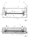
- Electrolysis cell 12 shows the electrolysis cell 12 in a schematic, non-scale sectional view.
- the functionally essential components of Electrolysis cell 12 comprises a membrane 100 and two electrodes, namely an anode 102 (eg as an oxygen electrode) and a cathode 104 (eg as a hydrogen electrode).
- the membrane 100 is a flexible structure, which in the present case is formed by a substrate made of a suitable plastic, such as Naflon, for example, and a suitable coating, preferably made of platinum-iridium, applied to the substrate. This coating is not shown in the drawing.
- the membrane 100 is designed so that water molecules H 2 O and hydrogen molecules H 2 , but no oxygen molecules O 2 can pass through them.
- the wet membrane 100 performs the function of the electrolyte necessary for the electrolysis, which in conventional electrolysis processes is generally formed by a liquid having a sufficient number of free anions and cations.
- the anode 102 does not directly adjoin the surface of the membrane 100, but the anode-side titanium nonwoven 106 is located between the anode 10 and the membrane 100.
- the cathode 104 does not directly adjoin the surface of the membrane 100, but the cathode-side titanium nonwoven 106 is located between the cathode 104 and the membrane 100.
- the anode 102 and the cathode 104 may be the same or similar.
- Each of the electrodes 102, 104 ie both the anode 102 and the cathode 104, each have a plate-shaped contact side 102.1, 104.1, which are plane-parallel to each other in the mounted state.
- the cathode 104 has on the contact side 104.1 a plurality of cathode-side channels 110, preferably annular channels 110, which are fluidically connected to a hydrogen outlet 108, as in Fig. 3 can be seen. These channels 110 are in Fig. 2 clearly recognizable because this figure is not drawn to scale.
- seals 114, 116 are provided, as in FIG Fig. 2 indicated.
- they are annular seals 114, 116 extending in respective annular grooves 128, 130 (see Fig. 4A, 4B . 5A, 5B ).
- these seals 114, 116 are highlighted as hatched areas.
- Fig. 3 a section is shown along another section line. This cut is to scale.
- the anode 102 includes an opening 120 for the water connection and an opening 122 for the oxygen / water connection.
- the inflowing water is indicated by a downwardly facing block arrow and the outflowing fluid (eg, O 2 and water) by an upwardly facing block arrow.
- the outflowing fluid eg, O 2 and water
- another outflowing fluid eg H 2 and water
- the passages 120, 122 extend substantially in the axial direction, while the hydrogen outlet 108 preferably extends radially outward.
- the cathode-side channels 110 are preferably connected via axially extending, cathode-side holes 112 with the radially outwardly facing hydrogen outlet 108. It is a fluidic connection that exists at least during operation of the cell 12.
- the flow connection can be switchable (eg via an integrated valve).
- FIGS. 4A to 4D Details of a possible anode 102 are shown.
- Fig. 4A shows a first section through the anode 102.
- screw holes (mounting holes) 126 are shown, which extend axially and the anode 102 completely penetrate.
- a plurality of such mounting holes 126 are located along the circular periphery of the anode 102 Fig. 2
- screws can be inserted through the mounting holes 126 of the anode 102 to screw the anode 102 to the cathode 104.
- the cathode has for this purpose screw holes 132, which are preferably provided with internal threads.
- the screw holes 132 of the cathode 104 are aligned with the attachment holes 126 of the anode 102.
- the anode has an annular concentric groove 128 which extends approximately on the outer circumference of the contact side 102.1 of the anode 102.
- an annular sealing ring 114 (see for example Fig. 2 ) are inserted or plugged in.
- a sealing body can be used, which itself carries a radially outwardly facing sealing ring.
- a section through the anode 102 is shown, which passes through the two openings 120, 122.
- Fig. 4C an enlargement of a portion of the contact side 102.1 of the anode 102 is shown.
- the contact side 102. 1 preferably has groove-like recesses 134 which are separated by webs 136.
- the groove-like recesses 134 may be parallel and straight next to each other. But it is also possible that the recesses 134 extend in two directions and the webs 136 then form quadrangular, square, rectangular or parallelogram-like projections or islands.
- the groove-like recesses 134 limit, together with each abutting region of the titanium nonwoven 106 and the membrane 100 a multi-arm flow channel or a plurality of flow channels and are sized so that they allow a promotion of the electrolysis cell 12 flowing fluids from the opening 120 to the opening 122 by capillary action.
- the groove-like recesses 134 preferably have a width of 1 mm and the intermediate webs 136 have a width of 1 mm.
- the height of the webs 136 may be, for example 0.9 mm, as in Fig. 4C shown.
- the structure on the contact side 102. 1 of the anode 102 can also be formed in another way; it merely has to form, together with the adjacent membrane surface, a multi-arm flow channel or a plurality of suitable flow channels suitable for the respective fluids and pressures.
- the formation of the groove-like recesses 134 in the anode 102 is particularly preferred.
- the titanium threads of which the titanium nonwovens 106, 108 are preferably constructed have a thickness between 10 and 100 ⁇ m, preferably between 15 and 25 ⁇ m.
- the corresponding thin "discs" or “sheets” of titanium nonwoven 106, 108 are preferably sintered from titanium filaments.
- the webs 106, 108 can be compressed denser or less dense. The closer the titanium material of the nonwovens 106, 108 is compressed, the better the support effect for the membrane 100 is. The membrane 100 is thus subject to a lower mechanical load. As a result, higher pressures can be achieved without damaging the membrane 100.
- the webs 106, 108 preferably have a material thickness between 0.5 and 1.5mm. Particularly preferred is a material thickness of 0.9 mm.
- the Titanium filaments are preferably cut from a film 20 microns thick and then pressed and sintered.
- the webs 106, 108 have a large porosity, which can be up to about 80%.
- the corresponding flow channel is bounded by the planar contact side 102. 1 of the anode 102, the titanium nonwoven 106 and the membrane 100.
- Fig. 4D a plan view of the dish-shaped anode 102 is shown. In this view, lying in the region of the circumference mounting holes 126 can be seen.
- the annular groove 128 for receiving a seal 114 extends concentrically to the center of the plate-shaped anode 102.
- the two openings 120 and 122 are hinted to recognize in the 9 o'clock and 3 o'clock position.
- the hatched circular area shown in the middle represents the mutually parallel recesses 134 of the contact side 102.1 of a possible embodiment of the invention.
- the anode-side titanium nonwoven 106 is placed on the contact side 102.1 or pressed to an intimate electrical and / or mechanical connection with the anode 102 to enter. If desired, the bond can be made so that the titanium mat 106 becomes a part of the anode 102.
- the gasket 114 may be fixed with an optional grub screw (not shown) that communicates with the gasket 114 through a radial screw hole 138.
- FIGS. 5A to 5C details of a possible cathode 104 (hydrogen electrode) are shown.
- Fig. 5A shows a first section through the cathode 104.
- screw holes (mounting holes) 132 are provided, which extend axially and the cathode 104 completely penetrate, as in Fig. 5C shown.
- the cathode 104 has an annular circumferential sealing groove 130 which is for receiving a sealing ring 116 is designed.
- the sealing ring 116 is preferably in the assembled state with the corresponding seal 114 in interaction to seal the cell 12.
- the sealing ring 116 can be fixed by a grub screw. For this grub screw, a radial screw hole 140 is provided.
- the contact surface 104.1 has the already described channels 110, preferably in the form of annular channels 110, on. These cathode-side channels 110 are preferably connected via axially extending, cathode-side holes 112 with the radially outwardly facing hydrogen outlet 108, as in Fig. 5B shown.
- Fig. 5C a plan view of the plate-shaped cathode 104 is shown.
- the peripheral screw holes 132 can be seen.
- the annular groove 130 for receiving the seal 116 extends concentrically with the center of the plate-shaped cathode 104.
- the annular channels 110 are also concentrically arranged and open into the cathode-side holes 112.
- the radially outwardly facing hydrogen outlet 108 is shown in phantom since lies below the lying in the plane of contact surface 104.1.
- the cathode-side titanium nonwoven 108 is placed on the contact side 104.1 or pressed to enter into an intimate electrical and / or mechanical connection with the cathode 104. If desired, the compound can be made so that the titanium mat 108 becomes a part of the cathode 104.
- a suitable material for the production of the electrodes 102, 104 is, for example, titanium. But it can also be used for other materials, and it is also possible to coat only the contact pages 102.1, 104.1, for example, with titanium or other metals.
- the materials chosen for the contact pages 102.1, 104.1 and the coating, must be chemically resistant to the substances involved in the process and must not have a damaging effect on the membrane 100. This applies to the material of the contact sides 102.1, 104.1, even if they are coated, since it would be very difficult to produce a completely pore-free coating.
- the electrodes 102, 104 can be produced, for example, by sintering.
- the groove-like recesses 134 and / or 110 of their contact sides 102.1, 104.1 can be produced by electro-erosion or by machining or chemical processing (eg etching). It should also be noted that the groove-like recesses 134 and / or 110 generally do not have an exactly rectangular channel cross-section, but are slightly rounded.
- the contact side 104.1 of the cathode 104 may have the same or a different structure as the contact side 102.1 of the anode 102. Preferred is an embodiment in which the contact side 102.1 of the anode 102 strip-shaped recesses 134 and the Contact side 104.1 of the cathode 104 have annular channels 110.
- the membrane 100 and the electrodes 102, 104 of the electrolysis cell 12 are preferably designed so that they do not need an actual housing.
- the material of the anode 102 and the cathode 104 and the shape are chosen so that the two electrodes 102, 104 by screwing together with the screw 124 an enclosed interior space (sealed by the seals 114, 116) form, where the sandwich of the two Woven 106, 108 and the membrane 100 is arranged.
- the cathode 104 With the circularly arranged on the outer circumference screw 124, the cathode 104 can be uniformly biased to the membrane 100 and the anode 102. Due to the high pressure generated in this way, a perfect and uniform electrical Contacting, even with very high usage pressure. For sealing a plurality of sealing body 114, 116, but no sealing compounds, provided.
- the anode-side part 102 have openings 120, 122 and the cathode-side part 104 has at least the opening 108 as an outlet.
- the openings 120, 122 are preferably designed for receiving hose or pipe connections (plug or screw). The same applies to the hydrogen outlet 108.
- a first fluid namely water H 2 O
- Fig. 1 passes according to Fig. 1 from the water tank 14, which is arranged above the electrolysis cell 12, through the water supply line 16 and through the water port forming opening 120 of the anode 102 in the region between the anode-side contact surface 102.1 and the membrane 100.
- the water flows through the groove-like recesses 134, if present, and wets at the same time the membrane 100, which assumes its function as an electrolyte in the wetted state and under electrical voltage.
- the electrolysis can begin, wherein a part of the supplied water into the second fluid, namely hydrogen H 2 , and the third fluid, namely oxygen O 2 , is decomposed.
- a portion of the undivided water remains on the anode side of the membrane 100, collects with the resulting oxygen in the groove-like recesses 134, if any, and leaves the electrolysis cell 12 through the opening 122 and the local oxygen / water connection.
- This oxygen / water mixture finally flows according to Fig. 1 via the oxygen / water return line 22 without pressure in the water tank 14 back.
- the method just described can also take place in the reverse manner; Hydrogen and oxygen produce water.
- the resulting water is taken from the then cell 12 acting as a fuel cell anode side of the membrane 100, and between the anode 102 and the cathode 104, an electrical voltage can be tapped.
- electrolysis cell 12 can be used according to the invention not only for the above-described electrolysis of water and the reverse reaction but with appropriate dimensioning and material selection for corresponding electrolysis or reverse reactions with other substances.
Landscapes
- Chemical & Material Sciences (AREA)
- Engineering & Computer Science (AREA)
- Chemical Kinetics & Catalysis (AREA)
- Electrochemistry (AREA)
- Manufacturing & Machinery (AREA)
- Life Sciences & Earth Sciences (AREA)
- Sustainable Development (AREA)
- Sustainable Energy (AREA)
- General Chemical & Material Sciences (AREA)
- Metallurgy (AREA)
- Organic Chemistry (AREA)
- Materials Engineering (AREA)
- Inorganic Chemistry (AREA)
- Electrolytic Production Of Non-Metals, Compounds, Apparatuses Therefor (AREA)
Applications Claiming Priority (1)
| Application Number | Priority Date | Filing Date | Title |
|---|---|---|---|
| CH01632/08A CH699769A2 (de) | 2008-10-16 | 2008-10-16 | Elektrolyse- beziehungsweise Brennstoff-Zelle und Verwendung der Elektrolyse- beziehungsweise Brennstoff-Zelle. |
Publications (1)
| Publication Number | Publication Date |
|---|---|
| EP2178144A1 true EP2178144A1 (fr) | 2010-04-21 |
Family
ID=41277471
Family Applications (1)
| Application Number | Title | Priority Date | Filing Date |
|---|---|---|---|
| EP09172385A Withdrawn EP2178144A1 (fr) | 2008-10-16 | 2009-10-07 | Cellule d'électrolyse ou de combustible et utilisation de la cellule d'électrolyse ou de combustible |
Country Status (2)
| Country | Link |
|---|---|
| EP (1) | EP2178144A1 (fr) |
| CH (1) | CH699769A2 (fr) |
Cited By (1)
| Publication number | Priority date | Publication date | Assignee | Title |
|---|---|---|---|---|
| AT524548B1 (de) * | 2021-08-13 | 2022-07-15 | H2i GreenHydrogen GmbH | Zellrahmen für eine Elektrolysezelle |
Citations (4)
| Publication number | Priority date | Publication date | Assignee | Title |
|---|---|---|---|---|
| EP1077499A2 (fr) | 1999-08-17 | 2001-02-21 | Schmidlin Labor + Service AG | Electrolyse ou pile à combustible, électrode d'électrolyse ou de pile à combustible et procédé d'electrolyse ou de pile à combustible |
| JP2004134135A (ja) * | 2002-10-08 | 2004-04-30 | National Institute Of Advanced Industrial & Technology | ガス拡散体と電極−電解質膜接合体との積層体 |
| EP1777323A2 (fr) * | 1997-03-21 | 2007-04-25 | Lynntech, Inc. | Système integré de génération d'ozone. |
| US20080067061A1 (en) * | 2003-07-14 | 2008-03-20 | Umicore Ag & Co. Kg | Membrane Electrode Unit for the Electrolysis of Water |
-
2008
- 2008-10-16 CH CH01632/08A patent/CH699769A2/de not_active Application Discontinuation
-
2009
- 2009-10-07 EP EP09172385A patent/EP2178144A1/fr not_active Withdrawn
Patent Citations (4)
| Publication number | Priority date | Publication date | Assignee | Title |
|---|---|---|---|---|
| EP1777323A2 (fr) * | 1997-03-21 | 2007-04-25 | Lynntech, Inc. | Système integré de génération d'ozone. |
| EP1077499A2 (fr) | 1999-08-17 | 2001-02-21 | Schmidlin Labor + Service AG | Electrolyse ou pile à combustible, électrode d'électrolyse ou de pile à combustible et procédé d'electrolyse ou de pile à combustible |
| JP2004134135A (ja) * | 2002-10-08 | 2004-04-30 | National Institute Of Advanced Industrial & Technology | ガス拡散体と電極−電解質膜接合体との積層体 |
| US20080067061A1 (en) * | 2003-07-14 | 2008-03-20 | Umicore Ag & Co. Kg | Membrane Electrode Unit for the Electrolysis of Water |
Cited By (2)
| Publication number | Priority date | Publication date | Assignee | Title |
|---|---|---|---|---|
| AT524548B1 (de) * | 2021-08-13 | 2022-07-15 | H2i GreenHydrogen GmbH | Zellrahmen für eine Elektrolysezelle |
| AT524548A4 (de) * | 2021-08-13 | 2022-07-15 | H2i GreenHydrogen GmbH | Zellrahmen für eine Elektrolysezelle |
Also Published As
| Publication number | Publication date |
|---|---|
| CH699769A2 (de) | 2010-04-30 |
Similar Documents
| Publication | Publication Date | Title |
|---|---|---|
| DE19542475C2 (de) | Polymerelektrolytmembran-Brennstoffzelle sowie Verfahren zur Herstellung einer Verteilerplatte für eine solche Zelle | |
| DE102008015333B4 (de) | Nanodraht-Strukturelement, Verfahren zu dessen Herstellung, Mikroreaktorsystem und Katalysatorsystem | |
| DE69736864T2 (de) | Elektrochemische Hochdruck-Zellen und Herstellungsverfahren | |
| DE10207743A1 (de) | Elektrode für eine Polymerelektrolyt-Brennstoffzelle, Trennwand hierfür sowie Polymerelektrolyt-Brennstoffzelle und Elektrizitätserzeugungssystem unter Verwendung derselben | |
| WO2022233386A1 (fr) | Empilement d'électrolyse de l'eau pour générer de l'hydrogène et de l'oxygène à partir d'eau | |
| WO2023117757A2 (fr) | Demi-cellule d'une cellule électrolytique d'un électrolyseur et procédé de fabrication d'un composant d'une cellule électrolytique | |
| WO2020109436A1 (fr) | Structure de distribution pour pile à combustible ou électrolyseur | |
| EP3834243A1 (fr) | Structure en couches pour une pile à combustible et procédé pour fabriquer une telle structure en couches | |
| EP2789038B1 (fr) | Empilement pour accumulateur d'énergie électrique | |
| EP2178144A1 (fr) | Cellule d'électrolyse ou de combustible et utilisation de la cellule d'électrolyse ou de combustible | |
| EP1077499A2 (fr) | Electrolyse ou pile à combustible, électrode d'électrolyse ou de pile à combustible et procédé d'electrolyse ou de pile à combustible | |
| WO2019185350A1 (fr) | Structure de répartiteur de gaz pour une pile à combustible | |
| WO2021198137A1 (fr) | Procédé de fabrication d'une structure conductrice de gaz et/ou d'électrons et pile à combustible/cellule d'électrolyse | |
| DE102014203150B4 (de) | Brennstoffzelle und Verfahren zur Herstellung eines Brennstoffzellenstapels | |
| EP4705542A1 (fr) | Empilement de cellules électrochimiques et procédé de fonctionnement d'un empilement de cellules électrochimiques | |
| DE102024114144A1 (de) | Separatorplatte und Zellrahmen für eine elektrochemische Vorrichtung | |
| DE60306916T2 (de) | Elektrochemischer generator mit einer bipolarplatte, welche eine vielzahl von der verteilung der gase dienenden löchern aufweist | |
| DE102013209226A1 (de) | Einzelelektrodenplatte zur Verwendung in einer Brennstoffzelle | |
| DE102021105029A1 (de) | Elektrochemische Einheit für eine elektrochemische Vorrichtung und Verfahren zum Herstellen einer elektrochemischen Einheit für eine elektrochemische Vorrichtung | |
| WO2023274912A1 (fr) | Plaque bipolaire pour la délimitation chimique et le montage en série électrique de piles à combustible pem ou d'électrolyseurs pem empilé(e)s | |
| DE102021105017A1 (de) | Elektrochemische Einheit für eine elektrochemische Vorrichtung und Verfahren zum Herstellen einer elektrochemischen Einheit für eine elektrochemische Vorrichtung | |
| DE2026219B2 (de) | Wasserabreicherungseinheit in filterpressenbauweise fuer brennstoffbatterien | |
| AT527374B1 (de) | Vorrichtung zur Durchführung eines elektrochemischen Verfahrens | |
| WO1992014953A1 (fr) | Procede et soupape interfaciale pour la separation d'un fluide | |
| EP4646500A2 (fr) | Plaque bipolaire pour électrolyseur |
Legal Events
| Date | Code | Title | Description |
|---|---|---|---|
| PUAI | Public reference made under article 153(3) epc to a published international application that has entered the european phase |
Free format text: ORIGINAL CODE: 0009012 |
|
| AK | Designated contracting states |
Kind code of ref document: A1 Designated state(s): AT BE BG CH CY CZ DE DK EE ES FI FR GB GR HR HU IE IS IT LI LT LU LV MC MK MT NL NO PL PT RO SE SI SK SM TR |
|
| 17P | Request for examination filed |
Effective date: 20100621 |
|
| STAA | Information on the status of an ep patent application or granted ep patent |
Free format text: STATUS: THE APPLICATION IS DEEMED TO BE WITHDRAWN |
|
| 18D | Application deemed to be withdrawn |
Effective date: 20110325 |