EP2178145B1 - Pile à combustible à oxyde solide et module de pile à combustible comprenant une telle pile à combustible à oxyde solide - Google Patents
Pile à combustible à oxyde solide et module de pile à combustible comprenant une telle pile à combustible à oxyde solide Download PDFInfo
- Publication number
- EP2178145B1 EP2178145B1 EP09173126A EP09173126A EP2178145B1 EP 2178145 B1 EP2178145 B1 EP 2178145B1 EP 09173126 A EP09173126 A EP 09173126A EP 09173126 A EP09173126 A EP 09173126A EP 2178145 B1 EP2178145 B1 EP 2178145B1
- Authority
- EP
- European Patent Office
- Prior art keywords
- fuel cell
- solid oxide
- air electrode
- current collecting
- collecting part
- Prior art date
- Legal status (The legal status is an assumption and is not a legal conclusion. Google has not performed a legal analysis and makes no representation as to the accuracy of the status listed.)
- Not-in-force
Links
- 239000000446 fuel Substances 0.000 title abstract description 166
- 239000007787 solid Substances 0.000 title abstract description 86
- KDLHZDBZIXYQEI-UHFFFAOYSA-N Palladium Chemical compound [Pd] KDLHZDBZIXYQEI-UHFFFAOYSA-N 0.000 abstract description 49
- 229910052751 metal Inorganic materials 0.000 abstract description 48
- 239000002184 metal Substances 0.000 abstract description 48
- 238000010248 power generation Methods 0.000 abstract description 23
- 229910052709 silver Inorganic materials 0.000 abstract description 22
- 239000003792 electrolyte Substances 0.000 abstract description 20
- 239000004332 silver Substances 0.000 abstract description 16
- 229910052763 palladium Inorganic materials 0.000 abstract description 15
- 239000000843 powder Substances 0.000 description 50
- 230000002093 peripheral effect Effects 0.000 description 27
- PXHVJJICTQNCMI-UHFFFAOYSA-N Nickel Chemical compound [Ni] PXHVJJICTQNCMI-UHFFFAOYSA-N 0.000 description 25
- 239000000463 material Substances 0.000 description 21
- BQCADISMDOOEFD-UHFFFAOYSA-N Silver Chemical compound [Ag] BQCADISMDOOEFD-UHFFFAOYSA-N 0.000 description 19
- 239000011248 coating agent Substances 0.000 description 14
- 238000000576 coating method Methods 0.000 description 14
- 239000010410 layer Substances 0.000 description 14
- 239000000203 mixture Substances 0.000 description 14
- 239000007789 gas Substances 0.000 description 13
- 239000010949 copper Substances 0.000 description 11
- 229910052759 nickel Inorganic materials 0.000 description 11
- SECXISVLQFMRJM-UHFFFAOYSA-N N-Methylpyrrolidone Chemical compound CN1CCCC1=O SECXISVLQFMRJM-UHFFFAOYSA-N 0.000 description 10
- 239000007784 solid electrolyte Substances 0.000 description 10
- 230000000052 comparative effect Effects 0.000 description 9
- 229920005989 resin Polymers 0.000 description 9
- 239000011347 resin Substances 0.000 description 9
- MCMNRKCIXSYSNV-UHFFFAOYSA-N Zirconium dioxide Chemical compound O=[Zr]=O MCMNRKCIXSYSNV-UHFFFAOYSA-N 0.000 description 8
- 229910052802 copper Inorganic materials 0.000 description 8
- 230000005611 electricity Effects 0.000 description 8
- 239000007788 liquid Substances 0.000 description 8
- 239000007800 oxidant agent Substances 0.000 description 8
- 239000002904 solvent Substances 0.000 description 8
- 229910001316 Ag alloy Inorganic materials 0.000 description 7
- 229910045601 alloy Inorganic materials 0.000 description 7
- 239000000956 alloy Substances 0.000 description 7
- 239000002737 fuel gas Substances 0.000 description 7
- 229910052712 strontium Inorganic materials 0.000 description 7
- WVDDGKGOMKODPV-UHFFFAOYSA-N Benzyl alcohol Chemical compound OCC1=CC=CC=C1 WVDDGKGOMKODPV-UHFFFAOYSA-N 0.000 description 6
- RYGMFSIKBFXOCR-UHFFFAOYSA-N Copper Chemical compound [Cu] RYGMFSIKBFXOCR-UHFFFAOYSA-N 0.000 description 6
- 239000000919 ceramic Substances 0.000 description 6
- 238000010586 diagram Methods 0.000 description 6
- 229910052760 oxygen Inorganic materials 0.000 description 6
- 239000001301 oxygen Substances 0.000 description 6
- BASFCYQUMIYNBI-UHFFFAOYSA-N platinum Chemical compound [Pt] BASFCYQUMIYNBI-UHFFFAOYSA-N 0.000 description 6
- 239000011575 calcium Substances 0.000 description 5
- 239000011195 cermet Substances 0.000 description 5
- CETPSERCERDGAM-UHFFFAOYSA-N ceric oxide Chemical compound O=[Ce]=O CETPSERCERDGAM-UHFFFAOYSA-N 0.000 description 4
- 229910000422 cerium(IV) oxide Inorganic materials 0.000 description 4
- 229910052746 lanthanum Inorganic materials 0.000 description 4
- FZLIPJUXYLNCLC-UHFFFAOYSA-N lanthanum atom Chemical compound [La] FZLIPJUXYLNCLC-UHFFFAOYSA-N 0.000 description 4
- 239000011148 porous material Substances 0.000 description 4
- 229910052761 rare earth metal Inorganic materials 0.000 description 4
- WEVYAHXRMPXWCK-UHFFFAOYSA-N Acetonitrile Chemical compound CC#N WEVYAHXRMPXWCK-UHFFFAOYSA-N 0.000 description 3
- CURLTUGMZLYLDI-UHFFFAOYSA-N Carbon dioxide Chemical compound O=C=O CURLTUGMZLYLDI-UHFFFAOYSA-N 0.000 description 3
- LFQSCWFLJHTTHZ-UHFFFAOYSA-N Ethanol Chemical compound CCO LFQSCWFLJHTTHZ-UHFFFAOYSA-N 0.000 description 3
- XEEYBQQBJWHFJM-UHFFFAOYSA-N Iron Chemical compound [Fe] XEEYBQQBJWHFJM-UHFFFAOYSA-N 0.000 description 3
- OKKJLVBELUTLKV-UHFFFAOYSA-N Methanol Chemical compound OC OKKJLVBELUTLKV-UHFFFAOYSA-N 0.000 description 3
- YXFVVABEGXRONW-UHFFFAOYSA-N Toluene Chemical compound CC1=CC=CC=C1 YXFVVABEGXRONW-UHFFFAOYSA-N 0.000 description 3
- QVGXLLKOCUKJST-UHFFFAOYSA-N atomic oxygen Chemical compound [O] QVGXLLKOCUKJST-UHFFFAOYSA-N 0.000 description 3
- 229910052791 calcium Inorganic materials 0.000 description 3
- 239000007772 electrode material Substances 0.000 description 3
- 238000011156 evaluation Methods 0.000 description 3
- 239000011777 magnesium Substances 0.000 description 3
- 239000012046 mixed solvent Substances 0.000 description 3
- -1 oxygen ions Chemical class 0.000 description 3
- 229910052697 platinum Inorganic materials 0.000 description 3
- 229920005749 polyurethane resin Polymers 0.000 description 3
- 239000000523 sample Substances 0.000 description 3
- 238000007581 slurry coating method Methods 0.000 description 3
- CIOAGBVUUVVLOB-UHFFFAOYSA-N strontium atom Chemical compound [Sr] CIOAGBVUUVVLOB-UHFFFAOYSA-N 0.000 description 3
- OYPRJOBELJOOCE-UHFFFAOYSA-N Calcium Chemical compound [Ca] OYPRJOBELJOOCE-UHFFFAOYSA-N 0.000 description 2
- VYZAMTAEIAYCRO-UHFFFAOYSA-N Chromium Chemical compound [Cr] VYZAMTAEIAYCRO-UHFFFAOYSA-N 0.000 description 2
- 229910002127 La0.6Sr0.4Co0.2Fe0.8O3 Inorganic materials 0.000 description 2
- 229910001252 Pd alloy Inorganic materials 0.000 description 2
- BQENXCOZCUHKRE-UHFFFAOYSA-N [La+3].[La+3].[O-][Mn]([O-])=O.[O-][Mn]([O-])=O.[O-][Mn]([O-])=O Chemical compound [La+3].[La+3].[O-][Mn]([O-])=O.[O-][Mn]([O-])=O.[O-][Mn]([O-])=O BQENXCOZCUHKRE-UHFFFAOYSA-N 0.000 description 2
- 239000000654 additive Substances 0.000 description 2
- 230000000996 additive effect Effects 0.000 description 2
- 238000010420 art technique Methods 0.000 description 2
- 235000019445 benzyl alcohol Nutrition 0.000 description 2
- 229910002092 carbon dioxide Inorganic materials 0.000 description 2
- 229910052804 chromium Inorganic materials 0.000 description 2
- 239000011651 chromium Substances 0.000 description 2
- KPLQYGBQNPPQGA-UHFFFAOYSA-N cobalt samarium Chemical compound [Co].[Sm] KPLQYGBQNPPQGA-UHFFFAOYSA-N 0.000 description 2
- 238000004891 communication Methods 0.000 description 2
- 238000010276 construction Methods 0.000 description 2
- 238000007796 conventional method Methods 0.000 description 2
- 235000012438 extruded product Nutrition 0.000 description 2
- 239000010419 fine particle Substances 0.000 description 2
- 238000010304 firing Methods 0.000 description 2
- LNTHITQWFMADLM-UHFFFAOYSA-N gallic acid Chemical compound OC(=O)C1=CC(O)=C(O)C(O)=C1 LNTHITQWFMADLM-UHFFFAOYSA-N 0.000 description 2
- PCHJSUWPFVWCPO-UHFFFAOYSA-N gold Chemical compound [Au] PCHJSUWPFVWCPO-UHFFFAOYSA-N 0.000 description 2
- 229910052737 gold Inorganic materials 0.000 description 2
- 239000010931 gold Substances 0.000 description 2
- 229910052742 iron Inorganic materials 0.000 description 2
- 229910052749 magnesium Inorganic materials 0.000 description 2
- UODXCYZDMHPIJE-UHFFFAOYSA-N menthanol Chemical compound CC1CCC(C(C)(C)O)CC1 UODXCYZDMHPIJE-UHFFFAOYSA-N 0.000 description 2
- 238000000034 method Methods 0.000 description 2
- 229910052574 oxide ceramic Inorganic materials 0.000 description 2
- 239000011224 oxide ceramic Substances 0.000 description 2
- AHKZTVQIVOEVFO-UHFFFAOYSA-N oxide(2-) Chemical compound [O-2] AHKZTVQIVOEVFO-UHFFFAOYSA-N 0.000 description 2
- 229910052702 rhenium Inorganic materials 0.000 description 2
- WUAPFZMCVAUBPE-UHFFFAOYSA-N rhenium atom Chemical compound [Re] WUAPFZMCVAUBPE-UHFFFAOYSA-N 0.000 description 2
- 229910052703 rhodium Inorganic materials 0.000 description 2
- 239000010948 rhodium Substances 0.000 description 2
- MHOVAHRLVXNVSD-UHFFFAOYSA-N rhodium atom Chemical compound [Rh] MHOVAHRLVXNVSD-UHFFFAOYSA-N 0.000 description 2
- 229910000938 samarium–cobalt magnet Inorganic materials 0.000 description 2
- 229910052706 scandium Inorganic materials 0.000 description 2
- 238000007650 screen-printing Methods 0.000 description 2
- 239000010935 stainless steel Substances 0.000 description 2
- 229910001220 stainless steel Inorganic materials 0.000 description 2
- 238000010345 tape casting Methods 0.000 description 2
- 238000012360 testing method Methods 0.000 description 2
- 229910052727 yttrium Inorganic materials 0.000 description 2
- 229910000859 α-Fe Inorganic materials 0.000 description 2
- WUOACPNHFRMFPN-SECBINFHSA-N (S)-(-)-alpha-terpineol Chemical compound CC1=CC[C@@H](C(C)(C)O)CC1 WUOACPNHFRMFPN-SECBINFHSA-N 0.000 description 1
- QCDWFXQBSFUVSP-UHFFFAOYSA-N 2-phenoxyethanol Chemical compound OCCOC1=CC=CC=C1 QCDWFXQBSFUVSP-UHFFFAOYSA-N 0.000 description 1
- 229920000178 Acrylic resin Polymers 0.000 description 1
- 239000004925 Acrylic resin Substances 0.000 description 1
- 229910052685 Curium Inorganic materials 0.000 description 1
- FYYHWMGAXLPEAU-UHFFFAOYSA-N Magnesium Chemical compound [Mg] FYYHWMGAXLPEAU-UHFFFAOYSA-N 0.000 description 1
- RTAQQCXQSZGOHL-UHFFFAOYSA-N Titanium Chemical compound [Ti] RTAQQCXQSZGOHL-UHFFFAOYSA-N 0.000 description 1
- PACGUUNWTMTWCF-UHFFFAOYSA-N [Sr].[La] Chemical compound [Sr].[La] PACGUUNWTMTWCF-UHFFFAOYSA-N 0.000 description 1
- 229910052784 alkaline earth metal Inorganic materials 0.000 description 1
- 150000001342 alkaline earth metals Chemical class 0.000 description 1
- OVKDFILSBMEKLT-UHFFFAOYSA-N alpha-Terpineol Natural products CC(=C)C1(O)CCC(C)=CC1 OVKDFILSBMEKLT-UHFFFAOYSA-N 0.000 description 1
- 229940088601 alpha-terpineol Drugs 0.000 description 1
- PNEYBMLMFCGWSK-UHFFFAOYSA-N aluminium oxide Inorganic materials [O-2].[O-2].[O-2].[Al+3].[Al+3] PNEYBMLMFCGWSK-UHFFFAOYSA-N 0.000 description 1
- 230000008901 benefit Effects 0.000 description 1
- 230000015572 biosynthetic process Effects 0.000 description 1
- 238000005219 brazing Methods 0.000 description 1
- QHIWVLPBUQWDMQ-UHFFFAOYSA-N butyl prop-2-enoate;methyl 2-methylprop-2-enoate;prop-2-enoic acid Chemical compound OC(=O)C=C.COC(=O)C(C)=C.CCCCOC(=O)C=C QHIWVLPBUQWDMQ-UHFFFAOYSA-N 0.000 description 1
- 239000001569 carbon dioxide Substances 0.000 description 1
- 230000008859 change Effects 0.000 description 1
- 238000006243 chemical reaction Methods 0.000 description 1
- 239000011247 coating layer Substances 0.000 description 1
- 229910017052 cobalt Inorganic materials 0.000 description 1
- 239000010941 cobalt Substances 0.000 description 1
- GUTLYIVDDKVIGB-UHFFFAOYSA-N cobalt atom Chemical compound [Co] GUTLYIVDDKVIGB-UHFFFAOYSA-N 0.000 description 1
- 229910052963 cobaltite Inorganic materials 0.000 description 1
- 239000002131 composite material Substances 0.000 description 1
- 150000001875 compounds Chemical class 0.000 description 1
- 239000004020 conductor Substances 0.000 description 1
- 238000005868 electrolysis reaction Methods 0.000 description 1
- 239000003822 epoxy resin Substances 0.000 description 1
- 239000011521 glass Substances 0.000 description 1
- LNEPOXFFQSENCJ-UHFFFAOYSA-N haloperidol Chemical compound C1CC(O)(C=2C=CC(Cl)=CC=2)CCN1CCCC(=O)C1=CC=C(F)C=C1 LNEPOXFFQSENCJ-UHFFFAOYSA-N 0.000 description 1
- 239000010416 ion conductor Substances 0.000 description 1
- 230000014759 maintenance of location Effects 0.000 description 1
- 238000004519 manufacturing process Methods 0.000 description 1
- 239000012528 membrane Substances 0.000 description 1
- 229910000510 noble metal Inorganic materials 0.000 description 1
- 239000002245 particle Substances 0.000 description 1
- 238000005192 partition Methods 0.000 description 1
- 239000005011 phenolic resin Substances 0.000 description 1
- 229960005323 phenoxyethanol Drugs 0.000 description 1
- WVDDGKGOMKODPV-ZQBYOMGUSA-N phenyl(114C)methanol Chemical compound O[14CH2]C1=CC=CC=C1 WVDDGKGOMKODPV-ZQBYOMGUSA-N 0.000 description 1
- 238000005498 polishing Methods 0.000 description 1
- 229920000647 polyepoxide Polymers 0.000 description 1
- 230000008569 process Effects 0.000 description 1
- 239000002994 raw material Substances 0.000 description 1
- SIXSYDAISGFNSX-UHFFFAOYSA-N scandium atom Chemical compound [Sc] SIXSYDAISGFNSX-UHFFFAOYSA-N 0.000 description 1
- 238000004528 spin coating Methods 0.000 description 1
- 238000005507 spraying Methods 0.000 description 1
- 229910002076 stabilized zirconia Inorganic materials 0.000 description 1
- 238000005728 strengthening Methods 0.000 description 1
- 229910052719 titanium Inorganic materials 0.000 description 1
- 239000010936 titanium Substances 0.000 description 1
- 229910052723 transition metal Inorganic materials 0.000 description 1
- 150000003624 transition metals Chemical class 0.000 description 1
- XLYOFNOQVPJJNP-UHFFFAOYSA-N water Substances O XLYOFNOQVPJJNP-UHFFFAOYSA-N 0.000 description 1
- VWQVUPCCIRVNHF-UHFFFAOYSA-N yttrium atom Chemical compound [Y] VWQVUPCCIRVNHF-UHFFFAOYSA-N 0.000 description 1
Images


Classifications
-
- H—ELECTRICITY
- H01—ELECTRIC ELEMENTS
- H01M—PROCESSES OR MEANS, e.g. BATTERIES, FOR THE DIRECT CONVERSION OF CHEMICAL ENERGY INTO ELECTRICAL ENERGY
- H01M8/00—Fuel cells; Manufacture thereof
- H01M8/02—Details
- H01M8/0202—Collectors; Separators, e.g. bipolar separators; Interconnectors
-
- H—ELECTRICITY
- H01—ELECTRIC ELEMENTS
- H01M—PROCESSES OR MEANS, e.g. BATTERIES, FOR THE DIRECT CONVERSION OF CHEMICAL ENERGY INTO ELECTRICAL ENERGY
- H01M8/00—Fuel cells; Manufacture thereof
- H01M8/02—Details
- H01M8/0202—Collectors; Separators, e.g. bipolar separators; Interconnectors
- H01M8/023—Porous and characterised by the material
- H01M8/0232—Metals or alloys
-
- H—ELECTRICITY
- H01—ELECTRIC ELEMENTS
- H01M—PROCESSES OR MEANS, e.g. BATTERIES, FOR THE DIRECT CONVERSION OF CHEMICAL ENERGY INTO ELECTRICAL ENERGY
- H01M8/00—Fuel cells; Manufacture thereof
- H01M8/02—Details
- H01M8/0202—Collectors; Separators, e.g. bipolar separators; Interconnectors
- H01M8/023—Porous and characterised by the material
- H01M8/0236—Glass; Ceramics; Cermets
-
- H—ELECTRICITY
- H01—ELECTRIC ELEMENTS
- H01M—PROCESSES OR MEANS, e.g. BATTERIES, FOR THE DIRECT CONVERSION OF CHEMICAL ENERGY INTO ELECTRICAL ENERGY
- H01M8/00—Fuel cells; Manufacture thereof
- H01M8/02—Details
- H01M8/0202—Collectors; Separators, e.g. bipolar separators; Interconnectors
- H01M8/023—Porous and characterised by the material
- H01M8/0241—Composites
- H01M8/0243—Composites in the form of mixtures
-
- H—ELECTRICITY
- H01—ELECTRIC ELEMENTS
- H01M—PROCESSES OR MEANS, e.g. BATTERIES, FOR THE DIRECT CONVERSION OF CHEMICAL ENERGY INTO ELECTRICAL ENERGY
- H01M8/00—Fuel cells; Manufacture thereof
- H01M8/10—Fuel cells with solid electrolytes
- H01M8/12—Fuel cells with solid electrolytes operating at high temperature, e.g. with stabilised ZrO2 electrolyte
- H01M2008/1293—Fuel cells with solid oxide electrolytes
-
- H—ELECTRICITY
- H01—ELECTRIC ELEMENTS
- H01M—PROCESSES OR MEANS, e.g. BATTERIES, FOR THE DIRECT CONVERSION OF CHEMICAL ENERGY INTO ELECTRICAL ENERGY
- H01M8/00—Fuel cells; Manufacture thereof
- H01M8/02—Details
- H01M8/0202—Collectors; Separators, e.g. bipolar separators; Interconnectors
- H01M8/0204—Non-porous and characterised by the material
- H01M8/0215—Glass; Ceramic materials
- H01M8/0217—Complex oxides, optionally doped, of the type AMO3, A being an alkaline earth metal or rare earth metal and M being a metal, e.g. perovskites
-
- Y—GENERAL TAGGING OF NEW TECHNOLOGICAL DEVELOPMENTS; GENERAL TAGGING OF CROSS-SECTIONAL TECHNOLOGIES SPANNING OVER SEVERAL SECTIONS OF THE IPC; TECHNICAL SUBJECTS COVERED BY FORMER USPC CROSS-REFERENCE ART COLLECTIONS [XRACs] AND DIGESTS
- Y02—TECHNOLOGIES OR APPLICATIONS FOR MITIGATION OR ADAPTATION AGAINST CLIMATE CHANGE
- Y02E—REDUCTION OF GREENHOUSE GAS [GHG] EMISSIONS, RELATED TO ENERGY GENERATION, TRANSMISSION OR DISTRIBUTION
- Y02E60/00—Enabling technologies; Technologies with a potential or indirect contribution to GHG emissions mitigation
- Y02E60/30—Hydrogen technology
- Y02E60/50—Fuel cells
Definitions
- the present invention relates to a solid oxide fuel cell and a fuel cell module comprising the solid oxide fuel cell.
- a fuel cell comprising a tubular fuel cell has hitherto been known (for example, Japanese Patent 2007-95442A ).
- the conventional solid oxide fuel cell comprises an air electrode coated with a silver paste, and the silver is exposed to air.
- Japanese Patent 2005-50636A & EP 1598 892 A describe a flat solid oxide fuel cell.
- An air electrode contact material on the inner side of the solid oxide fuel cell is held between a separator and an air electrode.
- the air electrode contact material comprises at least a silver powder or a silver alloy powder and a perovskite oxide powder.
- the claimed advantage of the air electrode contact material is that, without significantly sacrificing a power generation performance inherent in unit cells, an excellent power generation performance under an air environment can be realized and breaking of unit cells can also be suppressed.
- the addition amount of the perovskite oxide is so large that the electric resistance is increased and the power generation performance is low, when the air electrode contact material described in this prior art technique, that is, a composition comprising at least a silver powder or a silver alloy powder and a perovskite oxide powder, is applied to a current collecting part in the solid oxide fuel battery.
- the air electrode contact material described in this prior art technique that is, a composition comprising at least a silver powder or a silver alloy powder and a perovskite oxide powder
- the porous nature of the air electrode contact layer is lost. In this case, the power generation performance under an air atmosphere is lowered, and, further, unit cells are likely to be broken by sticking.
- the loss of the porous nature of the air electrode contact layer further brings about a tendency toward a lowering in power generation durability.
- Japanese Patent 2002-216807A describes a flat solid oxide fuel cell.
- An air electrode current collector provided on the inner side of the solid oxide fuel cell is held between a separator and an air electrode.
- the air electrode current collector in the solid oxide fuel cell is formed of a dispersion-strengthening type silver porous body comprising an oxide dispersed in a silver base.
- FR-A-2 796 861 discloses an oxide ion conductive ceramic membrane of an assembly consisting of a) a dense layer of opposite surfaces S and S' of a solid electrolyte having, at electrolysis temperature, an oxide ion conductive crystalline structure, b) two mixed porous conductive electrodes c) two porous current collectors and d) at least a porous coating layer.
- the current collectors preferably consist of a mixture of metal/"inert oxide” ceramic (such as alumina) or a mixture of a metal/"hybrid conductor” oxide ceramic (such as a perovskite material) or a mixture of a metal/"ion conductor” oxide ceramic (such as yttrium-stabilized zirconia), wherein the metal is mainly chosen from transition metals, more particularly from silver, copper and nickel, or from noble metals, more particularly from gold, platinum and palladium.
- metal/"inert oxide” ceramic such as alumina
- a metal/"hybrid conductor” oxide ceramic such as a perovskite material
- a metal/"ion conductor” oxide ceramic such as yttrium-stabilized zirconia
- JP 2008 234915 A discloses a collector material for the air electrode of a solid oxide fuel cell, said material comprising a perovskite oxide compound having alkaline earth metal, such as lanthanum strontium cobaltite (LSC), and a complex composite powder component having ceria fine particles doped to the perovskite complex oxide fine particles.
- LSC lanthanum strontium cobaltite
- the collector material is optionally covered with Ag particles to form a collector layer on the air electrode.
- WO 2007/093759 A discloses a solid oxide fuel cell module comprising a plurality of solid oxide fuel cells, each fuel cell comprising an anode electrode, an electrolyte and a cathode electrode, characterised in that the anode electrode comprises at least three layers, wherein the first layer comprises a metal and ceramic cermet, the second layer comprises a current collector embedded in a metal and ceramic cermet and the third layer comprises a metal and ceramic cermet.
- the metal of the cermet is preferably selected from copper, nickel, palladium, platinum, rhenium or rhodium
- the ceramic of the cermet comprises at least one of yttria-stabilised zirconia, ceria or perovskite
- the current collector comprises at least one of copper, nickel, palladium, platinum, rhenium or rhodium.
- the present inventors have now found that, when an air electrode current collector comprising silver and palladium and a perovskite oxide at a specific content ratio is applied to a solid oxide fuel cell, the solid oxide fuel cell has a high initial power generation performance and a good power generation durability.
- the present invention has been made based on such finding.
- an object of the present invention is to provide a solid oxide fuel cell having a high initial power generation performance and a good power generation durability.
- a solid oxide fuel cell comprising at least a fuel electrode, an electrolyte, an air electrode, and a current collecting part disposed on the air electrode, wherein the current collecting part comprises an electroconductive metal and an oxide, the electroconductive metal is silver and palladium, the oxide is a perovskite oxide, and the content of the oxide is more than 0 (zero) and less than 0.111 in terms of weight ratio to the electroconductive metal.
- a fuel cell module comprising the solid oxide fuel cell according to the present invention.
- the fuel cell according to the present invention is the same as a cell that comprises at least a fuel electrode, an electrolyte, and an air electrode and is usually classified or understood as a solid oxide fuel cell in the art, except that a current collecting part provided on the air electrode satisfies requirements which are described herein.
- the current collecting part disposed in the air electrode comprises an electroconductive metal and an oxide.
- the electroconductive metal is silver and palladium, and the oxide is a perovskite oxide.
- the content of the oxide is more than 0 (zero) and less than 0.111, preferably more than 0 (zero) and not more than 0.095, more preferably more than 0 (zero) and not more than 0.090, in terms of weight ratio to the electroconductive metal.
- the ratio can be determined by analyzing a surface or a cross section of the current collecting part with an electron probe micro analyzer (EPMA).
- EPMA electron probe micro analyzer
- the perovskite oxide is preferably La 0.6 Sr 0.4 Co 0.2 Fe 0.8 O 3 .
- the oxide constituting the current collecting part has the same composition as the air electrode.
- a specific example of the oxide is a lanthanum manganite doped with at least one element selected from strontium (Sr) and calcium (Ca), a lanthanum ferrite doped with at least one element selected from strontium (Sr), cobalt (Co), nickel (Ni), and copper (Cu), or a samarium cobalt doped with at least one element selected from strontium (Sr), iron (Fe), nickel (Ni), and copper (Cu).
- the current collecting part is porous. Air is Introduced through pores in the porous current collecting part and is utilized in power generation. Oxygen passed through the current collecting part is supplied into the air electrode, whereby a good power generation performance Is provided. Further, in the present invention, the electroconductivity of the current collecting part is higher than that of the air electrode, and, consequently, the current collection performance can be improved. In the present invention, the porous nature of the current collecting part is approximately 20 to 80% in terms of porosity.
- the porosity can be determined, for example, by embedding a cross section of a sample to be measured with a resin, polishing the assembly, photographing the surface of the cross section of the sample, with a specular surface exposed thereon, with SEM and analyzing the photographed image.
- Fig. 1 is a cross-sectional view of a solid oxide fuel cell in an embodiment of the present invention.
- a fuel cell unit 1 comprises a solid oxide fuel cell 6 and a fuel electrode terminal 24 and an air electrode terminal 26 provided at respective both ends of the solid oxide fuel cell 6.
- the solid oxide fuel cell comprises one solid oxide fuel cell 6 (tubular body), and the solid oxide fuel cell 6 is cylindrical.
- the solid oxide fuel cell 6 has a laminate structure comprising a current collecting part 44a, an air electrode 20, an electrolyte 18, and a fuel electrode 16 as viewed from the surface of the solid oxide fuel cell 6 exposed to an oxidizing agent gas.
- the solid oxide fuel cell 6 has a through-flow passage 15 that is provided on the inner side of the fuel electrode 16 and functions as a passage for a fuel gas.
- the current collecting part 44a is connected to the air electrode terminal 26 fixed to the other end 6b of the solid oxide fuel cell 6.
- the whole or a part of the air electrode 20 is covered with the current collecting part 44a. Electricity generated in the air electrode 20 flows in a cell axial direction of the current collecting part 44a and is taken out from the air electrode terminal 26.
- the cell axial direction refers to a direction identical to the direction of the fuel gas that flows through the through-flow passage 15. In the drawing, the cell axial direction is indicated by an arrow A.
- the fuel electrode terminal 24 fixed to one end 6a of the solid oxide fuel cell 6 is in contact with the fuel electrode 16 and functions to taken out electricity generated in the fuel electrode 16 from the fuel electrode terminal 24.
- the current collecting part 44a should satisfy the above requirements.
- the thickness of the current collecting part 44a is 0.1 to 50 ⁇ m, more preferably 0.5 to 30 ⁇ m.
- the fuel electrode 16 is formed of, for example, at least one of a mixture of nickel (Ni) with zirconia doped with at least one element selected from calcium (Ca) and rare earth elements such as yttrium (Y) and scandium (Sc), a mixture of Ni with ceria doped with at least one element selected from rare earth elements, and a mixture of Ni with lanthanum gallate doped with at least one element selected from Sr, magnesium (Mg), Co, Fe, and Cu.
- the electrolyte 18 is formed of, for example, at least one of zirconia doped with at least one element selected from rare earth elements such as Y and Sc, ceria doped with at least one element selected from rare earth elements, and lanthanum gallate doped with at least one element selected from Sr and Mg.
- the air electrode 20 Is formed of, for example, at least one of lanthanum manganite doped with at least one element selected from Sr and Ca, lanthanum ferrite doped with at least one element selected from Sr, Co, Ni, and Cu, and samarium cobalt and silver doped with at least one element selected from Sr, Fe, Ni, and Cu, and the like.
- the thickness of the fuel electrode 16 is generally approximately 1 to 5 mm.
- the thickness of the electrolyte 18 is generally approximately 1 to 100 ⁇ m.
- the thickness of the air electrode 20 is generally approximately 1 to 50 ⁇ m.
- a fuel electrode protruded peripheral surface 16a in which the fuel electrode 16 is protruded relative to the electrolyte 18 and the air electrode 20, and an electrolyte protruded peripheral surface 18a, In which the electrolyte 18 is protruded relative to the air electrode 20, are provided on one end 6a of the solid oxide fuel cell 6.
- the fuel electrode protruded peripheral surface 16a and the electrolyte protruded peripheral surface 18a constitute the outer peripheral surface of the solid oxide fuel cell 6.
- the air electrode 20 is covered with the current collecting part 44a.
- the fuel electrode protruded peripheral surface 16a is also a fuel electrode outer peripheral surface 21 connected electrically to the fuel electrode 16.
- the fuel electrode terminal 24 comprises a body part 24a, which is disposed so as to cover the whole circumference of the fuel electrode outer peripheral surface 21 from the outside of the fuel electrode outer peripheral surface 21 and is connected electrically to the fuel electrode outer peripheral surface 21, and a tubular part 24b, which is extended in a longitudinal direction of the solid oxide fuel cell 6 so that a distance from the solid oxide fuel cell 6 is increased.
- the body part 24a and the tubular part 24b are cylindrical and are concentrically disposed.
- the tube diameter of the tubular part 24b is smaller than the tube diameter of the body part 24a.
- the body part 24a and the tubular part 24b have a connecting flow passage 24c that is in communication with the through-flow passage 15 and is connected to the outside of the solid oxide fuel cell unit 1.
- a step part 24d between the body part 24a and the tubular part 24b is abutted against an end face 16b of the fuel electrode 16.
- the air electrode terminal 26 comprises a body part 26a, which is disposed so as to cover the whole circumference of an air electrode outer peripheral surface 22 from the outside of the air electrode outer peripheral surface 22 and is connected electrically to the air electrode outer peripheral surface 22, and a tubular part 26b, which is extended in a longitudinal direction of the solid oxide fuel cell 6 so as to increase a distance from the solid oxide fuel cell 6.
- the body part 26a and the tubular part 26b are cylindrical and are concentrically disposed.
- the tube diameter of the tubular part 26b is smaller than the tube diameter of the body part 26a.
- the body part 26a and the tubular part 26b have a connecting flow passage 26c that is in communication with the through-flow passage 15 and is connected to the outside of the solid oxide fuel cell unit 1.
- a step part 26d between the body part 26a and the tubular part 26b is abutted against the current collecting part 44a, the air electrode 20, electrolyte 18, and an end face 16c of the fuel electrode 16 through an annular insulating member 28.
- the tubular part 24b in the fuel electrode terminal 24 and the tubular part 26b in the air electrode terminal 26 are identical to each other in the sectional shape of the outer contour. More preferably, the whole shape of the fuel electrode terminal 24 is identical to the whole shape of the air electrode terminal 26.
- the fuel electrode terminal 24 and the air electrode terminal 26 are formed of a heat resistant metal such as silver (Ag), a stainless steel, a nickel base alloy, or a chromium base alloy.
- the fuel electrode terminal 24 and the solid oxide fuel cell 6 are sealed and fixed over the whole circumference thereof with an electroconductive seal material 32.
- the air electrode terminal 26 and the fuel cell 6 are sealed and fixed over the whole circumference thereof with an electroconductive seal material 32.
- the fuel electrode protruded peripheral surface 16a and the electrolyte protruded peripheral surface 18a are extended over the whole circumference of the solid oxide fuel cell 6 and are adjacent to each other in a longitudinal direction A. Further, the fuel electrode protruded peripheral surface 16a is located at a front end 6c of the solid oxide fuel cell 6. A boundary 34 between the fuel electrode protruded peripheral surface 16a and the electrolyte protruded peripheral surface 18a is located within the body part 24a in the fuel electrode terminal 24. A boundary 36 between the electrolyte protruded peripheral surface 18 and the current collecting part protruded peripheral surface 44 is located on the outside of the body part 24a.
- the electrolyte protruded peripheral surface 18a has a taper part 18b with the thickness thereof being reduced toward the fuel electrode protruded peripheral surface 16a.
- the seal material 32 astrldes the fuel electrode protruded peripheral surface 16a and the electrolyte protruded peripheral surface 18a, is extended over the whole circumference thereof, is filled into the body part 24a in the fuel electrode terminal 24, and is distant from the air electrode 20 through the electrolyte protruded peripheral surface 18a.
- the seal material 32 is extended on the air electrode protruded peripheral surface 20a over the whole circumference thereof and is filled into a space between the body part 26a in the air electrode terminal 26 and the insulating member 28.
- the seal material 32 is provided so as to partition an area of gas, which acts on the fuel electrode 16, that is, the through-flow passage 15 and the connecting flow passages 24c, 26c, from an area of gas, which acts on the air electrode 20.
- Various brazing materials including silver, a mixture of silver with glass, gold, nickel, copper, or titanium are used as the seal material 32.
- the electricity can be taken out to the outside of the fuel cell unit 1 by connecting the air electrode and the fuel electrode with an external circuit.
- H 2 + O 2 - ⁇ H 2 O + 2 e - (1) CO + Q 2 - ⁇ CO 2 + 2 e - (2) 1/2 O 2 + 2 e - ⁇ O 2 - (3)
- gas which acts on the fuel electrode 16
- gas oxidizing agent gas
- gas which acts on the air electrode 20
- the solid oxide fuel cell 6 is activated. Electricity in the fuel electrode 16 is taken out through the seal material 32 and the fuel electrode terminal 24, and electricity in the air electrode 20 is taken out through the seal material 32 and the air electrode terminal 26.
- Fig. 2 is a diagram showing an embodiment of a solid oxide fuel cell unit in another embodiment of the present invention.
- a cell unit 2 comprises a solid oxide fuel cell 7 and two terminals.
- the solid oxide fuel cell 7 comprises a solid electrolyte provided on the outer side of a fuel electrode support having a through-flow passage in its interior, and an air electrode provided on the outer side of the solid electrolyte.
- a current collecting part is provided on the outer side of the air electrode.
- the solid oxide fuel cell 7 comprises one end 56a and the other end 56b.
- the other end 56b has two terminals. Specifically, a fuel electrode terminal 104 is provided on the inner side of the other end 56b, and an air electrode terminal 106 is provided on the outer side of the other end 56b.
- FIG. 3 shows the fuel electrode terminal 104 provided on the Inner side of the other end 56b.
- the fuel electrode terminal 104 is inserted into the through-flow passage in the fuel electrode and is In contact with the fuel electrode.
- the fuel electrode terminal 104 is substantially cylindrical from the viewpoint of increasing the area of contact with the solid oxide fuel cell 7 inserted in its central part.
- Fig. 4 is the air electrode terminal 106 provided on the outer side of the other end 56b.
- the air electrode terminal 106 is in contact with a current collecting part 144a covering the outer side of the air electrode.
- the air electrode terminal 106 is substantially cylindrical so that the solid oxide fuel cell 7 can be inserted in the central part of the air electrode terminal 106.
- the fuel electrode terminal 104 and the air electrode terminal 106 are formed of a heat resistant metal such as silver (Ag), a stainless steel, a nickel base alloy, or a chromium base alloy and are fixed to the cell by utilizing a spring force possessed by the metal.
- a heat resistant metal such as silver (Ag), a stainless steel, a nickel base alloy, or a chromium base alloy
- a fuel gas for example, H 2 or CO
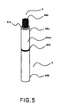
- Fig. 5 is a solid oxide fuel cell unit 3 in a further embodiment of the present invention.
- the solid oxide fuel cell unit 3 has a cell construction comprising a solid electrolyte provided on the outer side of a fuel electrode support having a through-flow passage in its interior, and an air electrode provided on the outer side of the solid electrolyte.
- a current collecting part is provided on the outer side of the air electrode.
- a solid oxide fuel cell 8 comprises one end 66a and the other end 66b.
- An electrolyte protruded part 214 in which the electrolyte is protruded relative to the air electrode, is provided at the one end 66a.
- An Ag wire which is an air electrode terminal 206, is wound around the outer circumference of the current collecting part 244a and is provided around the center of the solid oxide fuel cell 8.
- the current collecting part 244a at its position around which the wire is wound is not limited to the position around the center of the current collecting part 244a, and the wire may be wound around the other end 66b of the solid oxide fuel cell 8.
- a fuel electrode terminal 204 comprises a cylindrical Ag mesh having a size larger than the inner diameter of the through-flow passage. The fuel electrode terminal 204 is inserted into the solid oxide fuel cell 8 to a depth of 10 to 100 mm from the one end 66a and is brought to contact with the fuel electrode by a spring force of the Ag mesh. As with the embodiment shown in Fig.
- solid oxide fuel cells have been described above. However, the above constructions may also be applied to a solid oxide fuel cell module comprising a solid oxide fuel cell that is housed in an insulating container and is exposed to an oxidizing agent gas.
- the shape of the solid oxide fuel cell is not limited to a cylindrical shape and may have a flat shape or the like.
- the solid oxide fuel cell according to the present invention may be properly manufactured by a conventional method.
- the current collecting part provided on the air electrode may be appropriately formed by a method similar to the conventional method.
- a preferred manufacturing method is as follows. At the outset, silver, palladium, and oxide powders are provided and are weighed so as to give a composition identical to the compositon of the final current collecting part. The powders, together with a resin, are mixed with a solvent to give a coating liquid. The coating liquid is coated onto an air electrode, and the coating is dried and is then fired to form a current collector.
- the coating liquid may be coated onto the air electrode by slurry coating, tape casting, doctor blading, screen printing, spin coating, spraying, flow coating, and roll coating which may be used either solely or in a combination of two or more.
- resins usable herein include polyurethane resins, acrylic resins, epoxy resins, and phenol resins.
- Solvents include ethanol, methanol, ⁇ -terpineol, dihydroterpineol, n-methyl-2-pyrrolidone, benzyl alcohol, toluene, acetonitrile, 2-phenoxyethanol, and mixed solvents thereof.
- the coverage of the coating liquid onto the air electrode may be properly determined by taking into consideration the thickness of the final current collecting part.
- the coating is dried at about 50 to 150°C for 0.5 to 5 hr and is fired at about 400 to 800°C for 0.5 to 5 hr.
- a fuel electrode support was produced as follows. Specifically, a mixture of an NiO powder with a powder of (ZrO 2 ) 0.90 (Y 2 O 3 ) 0.10 (hereinafter abbreviated to "YSZ”) was prepared by a wet mixing process. The mixture was heat treated and ground to give a raw material powder for a fuel electrode support. The mixing ratio between the NIO powder and the YSZ powder was 65/35 In terms of weight ratio. The powder was extruded to form a cylindrical extruded product. The extruded product was heat treated at 900°C to prepare a calcined product of a fuel electrode support.
- YSZ powder of (ZrO 2 ) 0.90 (Y 2 O 3 ) 0.10
- a solid electrolyte film was formed by slurry coating on the surface of the fuel electrode support and was fired at 1300°C.
- the fuel electrode support with the solid electrolyte formed thereon had an outer diameter of 10.4 mm, a wall thickness of 1.5 mm, and an effective cell length of 100 mm in terms of dimension after firing.
- an air electrode was formed by slurry coating on the surface of the solid electrolyte, followed by firing at 1100°C.
- Table 1 La 0.6 Sr 0.4 Co 0.2 Fe 0.8 O 3 (hereinafter abbreviated to "LSCF”) was used as the air electrode.
- the area of the air electrode was 25.2 cm 2 .
- the coating liquid comprised a resin, a solvent, and a metal powder.
- a polyurethane resin was used as the resin
- a mixed solvent composed of n-methyl-2-pyrrolidone (NMP) and benzyl alcohol at a mixing ratio of 50 : 50 was used as the solvent
- an Ag powder and a Pd powder were used as the powder of the electroconductive metal
- La 0.6 Sr 0.4 Co 0.2 F 0.8 O 3 (LSCF) which was also used as the air electrode material, was used as the oxide.
- the resin, the solvent, the metal powder, and the oxide powder were mixed together, and the mixture was stirred.
- "wt%" of the additive materials is % by weight of the metal powder (Ag, Pd) and the oxide (LSCF) contained in the current collecting part when the amount of the current collecting part was presumed to be 100% by weight.
- the content of the oxide in the current collecting part was 0.087 in terms of the ratio to the electroconductive metal.
- the coating liquid was coated onto the solid oxide fuel cell by screen printing.
- the coating was then dried at 80°C for 30 min, was cooled at room temperature, and was then fired at 700°C for one hr to produce a solid oxide fuel cell comprising the current collecting part provided on the outer side of the air electrode.
- the current collecting part In the solid oxide fuel cell was formed of a film comprising Ag, Pd, and LSCF. More specifically, the current collecting part was formed of a film comprising 90.0% by weight of Ag, 2.0% by weight of Pd, and 8.0% by weight of LSCF.
- the content of an alloy containing Ag, Pd, and LSCF in the current collecting part was determined by subjecting the surface and cross section of the current collecting part in the cell to EPMA analysis.
- the content of the alloy was as shown in Table 1.
- a solid oxide fuel cell comprising a current collecting part provided on the outer side of an air electrode was produced in the same manner as in Example 1, except that, as shown in Table 1, the contents of the metal powder and the oxide powder in the current collecting part were 92.0% by weight for Ag, 2.0% by weight for Pd, and 6.0% by weight for LSCF. The content of the oxide in the current collecting part was 0.064 in terms of ratio to the electroconductive metal.
- a solid oxide fuel cell comprising a current collecting part provided on the outer side of an air electrode was produced In the same manner as in Example 1, except that, as shown in Table 1, the contents of the metal powder and the oxide powder in the current collecting part were 94.0% by weight for Ag, 2.0% by weight for Pd, and 4.0% by weight for LSCF. The content of the oxide In the current collecting part was 0.042 in terms of ratio to the electroconductive metal.
- a solid oxide fuel cell comprising a current collecting part provided on the outer side of an air electrode was produced in the same manner as In Example 1, except that, as shown in Table 1, the contents of the metal powder and the oxide powder in the current collecting part were 96.0% by weight for Ag, 2.0% by weight for Pd, and 2.0% by weight for LSCF. The content of the oxide in the current collecting part was 0.020 in terms of ratio to the electroconductive metal.
- a solid oxide fuel cell comprising a current collecting part provided on the outer side of an air electrode was produced In the same manner as in Example 1, except that, as shown in Table 1, the contents of the metal powder and the oxide powder in the current collecting part were 97.0% by weight for Ag, 2.0% by weight for Pd, and 1.0% by weight for LSCF. The content of the oxide in the current collecting part was 0.010 in terms of ratio to the electroconductive metal.
- a solid oxide fuel cell comprising a current collecting part provided on the outer side of an air electrode was produced in the same manner as in Example 1, except that, as shown in Table 1, the contents of the metal powder and the oxide powder in the current collecting part were 97.5% by weight for Ag, 2.0% by weight for Pd, and 0.5% by weight for LSCF. The content of the oxide in the current collecting part was 0.005 In terms of ratio to the electroconductive metal.
- a solid oxide fuel cell comprising a current collecting part provided on the outer side of an air electrode was produced in the same manner as in Example 1, except that, as shown in Table 1, the contents of the metal powder and the oxide powder in the current collecting part were 68.0% by weight for Ag, 2.0% by weight for Pd, and 30.0% by weight for LSCF. The content of the oxide In the current collecting part was 0.429 in terms of ratio to the electroconductive metal.
- a solid oxide fuel cell comprising a current collecting part provided on the outer side of an air electrode was produced in the same manner as in Example 1, except that, as shown in Table 1, the contents of the metal powder and the oxide powder in the current collecting part were 88.0% by weight for Ag, 2.0% by weight for Pd, and 10.0% by weight for LSCF. The content of the oxide in the current collecting part was 0.111 in terms of ratio to the electroconductive metal.
- a solid oxide fuel cell was produced in the same manner as in Example 1, except that the current collecting part had a two-layer structure comprising a first layer of Ag and Pd and a second layer of Ag formed on the first layer.
- Two types of coating liquids were provided for current collecting part formation.
- a polyurethane resin was used as the resin
- a mixed solvent composed of n-methyl-2-pyrrolidone (NMP) and benzyl alcohol at a mixing ratio of 50 : 50 was provided as the solvent
- an Ag powder and a Pd powder were provided as the powder of the electroconductive metal.
- the metal powders were weighed as specified in Table 2.
- the first solution was coated onto the air electrode in the solid oxide fuel cell, and the coated air electrode was then dried at 80°C for 30 min and was cooled at room temperature.
- the second solution was then coated thereon, and the assembly was dried at 80°C for 30 min, was cooled at room temperature, and was then fired at 700°C for one hr to produce a solid oxide fuel cell comprising the current collecting part provided on the outer side of the air electrode. That is, in the solid oxide fuel cell, the current collecting part was formed of an Ag/Pd alloy, and only Ag was exposed on the surface side without exposure of Pd on the surface side.
- the content of an alloy containing Ag and Pd in the current collecting part was determined by subjecting the surface or cross section of the current collecting part in the cell to EPMA analysis. The content thus determined was equal to that shown in Table 2.
- the first solution coated part was an Ag/Pd alloy comprising 98.0% by weight of Ag and 2.0% by weight of Pd
- the second solution coated part was 100% by weight of Ag.
- Power generation was performed using a mixed gas composed of H 2 and N 2 as a fuel.
- the utilization rate of fuel was 75%. Air was used as an oxidizing agent gas.
- the power generation potential was measured under conditions of a measuring temperature of 700°C and a current density of 0.3 A/cm 2 .
- the percentage change of power generation potential from the Initial power generation potential was determined as a percentage potential lowering.
- the percentage potential lowering after a 100-hr durability test exhibits a power generation performance retention of the solid oxide fuel cell. The lower the percentage potential lowering, the better the solid oxide fuel cell performance.
- Examples 1 to 6 the power generation durability was good. In particular, for Examples 3 to 5, the percentage potential lowering indicating power generation durability after 100 hr was good and on the order of 0.18%.
- the microstructure of the current collecting part was observed under SEM (scanning electron microscope). As a result, a number of pores were observed on the surface and cross section of the current collecting part, suggesting that, by virtue of the pores In the current collecting part, a satisfactory amount of oxygen was passed through the current collecting part and was supplied to the air electrode resulting in the good power generation performance.
- the percentage potential lowering after 100 hr was high and not less than 1.0%. Further, for the Comparative Examples, the adhesion of the current collecting part to the air electrode LSCF as the base material was deteriorated resulting in increased percentage potential powering.
Landscapes
- Chemical & Material Sciences (AREA)
- Engineering & Computer Science (AREA)
- Sustainable Energy (AREA)
- Life Sciences & Earth Sciences (AREA)
- Manufacturing & Machinery (AREA)
- Sustainable Development (AREA)
- Chemical Kinetics & Catalysis (AREA)
- Electrochemistry (AREA)
- General Chemical & Material Sciences (AREA)
- Ceramic Engineering (AREA)
- Composite Materials (AREA)
- Fuel Cell (AREA)
- Inert Electrodes (AREA)
Claims (6)
- Pile à combustible à oxyde solide comprenant une électrode à combustible, un électrolyte, une électrode à air et une partie collectrice de courant sur l'électrode à air, dans laquelle
la partie collectrice de courant comprend un métal électroconducteur et un oxyde, le métal électroconducteur est l'argent et le palladium, l'oxyde est un oxyde de pérovskite, et la teneur de l'oxyde est supérieure à 0 (zéro) et inférieure à 0,111 en termes de rapport de poids par rapport au métal électroconducteur. - Pile à combustible à oxyde solide selon la revendication 1, dans laquelle l'oxyde de pérovskite est un manganite de lanthane dopé avec au moins un élément choisi parmi le strontium (Sr) et le calcium (Ca), un ferrite de lanthane dopé avec au moins un élément choisi parmi le strontium (Sr), le cobalt (Co), le nickel (Ni) et le cuivre (Cu), ou un cobalt de samarium dopé avec au moins un élément choisi parmi le strontium (Sr), le fer (Fe), le nickel (Ni) et le cuivre (Cu).
- Pile à combustible à oxyde solide selon la revendication 1, dans laquelle l'oxyde de pérovskite est La0,6Sr0,4Co0,2Fe0,8O3.
- Pile à combustible à oxyde solide selon la revendication 1, dans laquelle l'oxyde présente la même composition que l'électrode à air.
- Pile à combustible à oxyde solide selon la revendication 1, dans laquelle le rapport de l'oxyde sur le métal électroconducteur est supérieur à 0 (zéro) et non supérieur à 0,095.
- Module de pile à combustible à oxyde solide comprenant une pile à combustible selon la revendication 1.
Applications Claiming Priority (1)
| Application Number | Priority Date | Filing Date | Title |
|---|---|---|---|
| JP2008267064 | 2008-10-16 |
Publications (2)
| Publication Number | Publication Date |
|---|---|
| EP2178145A1 EP2178145A1 (fr) | 2010-04-21 |
| EP2178145B1 true EP2178145B1 (fr) | 2011-10-12 |
Family
ID=41395002
Family Applications (1)
| Application Number | Title | Priority Date | Filing Date |
|---|---|---|---|
| EP09173126A Not-in-force EP2178145B1 (fr) | 2008-10-16 | 2009-10-15 | Pile à combustible à oxyde solide et module de pile à combustible comprenant une telle pile à combustible à oxyde solide |
Country Status (5)
| Country | Link |
|---|---|
| US (1) | US8722278B2 (fr) |
| EP (1) | EP2178145B1 (fr) |
| JP (1) | JP5418975B2 (fr) |
| CN (1) | CN101728558B (fr) |
| AT (1) | ATE528815T1 (fr) |
Families Citing this family (14)
| Publication number | Priority date | Publication date | Assignee | Title |
|---|---|---|---|---|
| KR101761346B1 (ko) * | 2009-10-16 | 2017-07-25 | 인하대학교 산학협력단 | 연료극 재료 및 이를 포함하는 고체 산화물 연료전지 |
| JP4995327B1 (ja) * | 2010-03-25 | 2012-08-08 | 日本碍子株式会社 | 電極材料、それを含む燃料電池セル、及びその製造方法 |
| KR20120008274A (ko) * | 2010-07-16 | 2012-01-30 | 삼성에스디아이 주식회사 | 고체산화물 연료전지 및 연료전지 스택 |
| JP4955830B1 (ja) * | 2010-12-13 | 2012-06-20 | 日本碍子株式会社 | 固体酸化物形燃料電池 |
| JP5834914B2 (ja) * | 2011-12-29 | 2015-12-24 | Toto株式会社 | 固体酸化物形燃料電池セル |
| EP2642570B1 (fr) * | 2012-03-23 | 2015-12-16 | Institute of Nuclear Energy Research Atomic Energy Council, Executive Yuan | Un appareil de collecte de courant et procédé de traitement d'une cellule à combustible à oxyde solide de tels éléments |
| JP6191429B2 (ja) * | 2012-12-10 | 2017-09-06 | Toto株式会社 | 固体酸化物形燃料電池セル |
| JP5805232B2 (ja) * | 2013-03-13 | 2015-11-04 | 日本碍子株式会社 | 固体酸化物型燃料電池 |
| EP2822075A1 (fr) * | 2013-07-03 | 2015-01-07 | Toto Ltd. | Cellule à combustible d'oxyde solide |
| CN104733657A (zh) * | 2015-03-31 | 2015-06-24 | 昆山艾可芬能源科技有限公司 | 一种固体氧化物燃料电池堆用密封材料 |
| JP2018098081A (ja) * | 2016-12-14 | 2018-06-21 | Toto株式会社 | 固体酸化物形燃料電池スタック |
| TWI763812B (zh) * | 2017-03-31 | 2022-05-11 | 日商大阪瓦斯股份有限公司 | 電化學裝置、能源系統、及固態氧化物型燃料電池 |
| CN109841844A (zh) * | 2017-11-28 | 2019-06-04 | 中国科学院大连化学物理研究所 | 一种锰酸镧基阴极支撑固体氧化物燃料电池及其应用 |
| JP7103783B2 (ja) * | 2017-12-07 | 2022-07-20 | 株式会社ノリタケカンパニーリミテド | 接合材および接合体 |
Family Cites Families (19)
| Publication number | Priority date | Publication date | Assignee | Title |
|---|---|---|---|---|
| FR2796861B1 (fr) | 1999-07-26 | 2001-11-09 | Air Liquide | Nouvelle membrane ceramique conductrice par ions oxyde, utilisation de ladite membrane pour separer l'oxygene de l' air ou d'un melange gazeux en contenant |
| US7378173B2 (en) * | 2000-05-18 | 2008-05-27 | Corning Incorporated | Fuel cells with enhanced via fill compositions and/or enhanced via fill geometries |
| KR20040002847A (ko) * | 2000-11-16 | 2004-01-07 | 미쓰비시 마테리알 가부시키가이샤 | 고체 전해질형 연료전지 및 그것에 사용하는 공기극 집전체 |
| JP3924772B2 (ja) | 2000-11-16 | 2007-06-06 | 三菱マテリアル株式会社 | 固体電解質型燃料電池の空気極集電体 |
| JP3976181B2 (ja) * | 2002-07-19 | 2007-09-12 | 東邦瓦斯株式会社 | 固体酸化物燃料電池単セル及びこれを用いた固体酸化物燃料電池 |
| JP4370784B2 (ja) * | 2003-02-04 | 2009-11-25 | 日産自動車株式会社 | 固体電解質型燃料電池 |
| US7943270B2 (en) * | 2003-06-10 | 2011-05-17 | Celltech Power Llc | Electrochemical device configurations |
| JP4442747B2 (ja) * | 2003-07-28 | 2010-03-31 | 東邦瓦斯株式会社 | 空気極用コンタクト材料およびこれを用いた固体酸化物形燃料電池 |
| JP4476689B2 (ja) | 2004-05-11 | 2010-06-09 | 東邦瓦斯株式会社 | 低温作動型固体酸化物形燃料電池単セル |
| JP5072188B2 (ja) * | 2005-03-01 | 2012-11-14 | 東邦瓦斯株式会社 | 集電材フィルムおよびこれを用いた平板型固体酸化物形燃料電池 |
| JP2007095442A (ja) | 2005-09-28 | 2007-04-12 | Toto Ltd | 固体酸化物形燃料電池 |
| JP5242909B2 (ja) * | 2005-11-14 | 2013-07-24 | 日本電信電話株式会社 | 固体酸化物形燃料電池 |
| GB0602842D0 (en) | 2006-02-14 | 2006-03-22 | Rolls Royce Plc | A Solid Oxide Fuel Cell And A Solid Oxide Fuel Cell Module |
| JP2008159571A (ja) * | 2006-11-30 | 2008-07-10 | Central Res Inst Of Electric Power Ind | 銀粒子担持多孔質セラミックス電極及び集電体の製造方法 |
| US20090186250A1 (en) * | 2006-12-28 | 2009-07-23 | Saint-Gobain Ceramics & Plastics, Inc. | Bilayer interconnects for solid oxide fuel cells |
| JP2008234915A (ja) | 2007-03-19 | 2008-10-02 | Hosokawa Funtai Gijutsu Kenkyusho:Kk | 固体酸化物形燃料電池の集電体材料、空気極集電体及び固体酸化物形燃料電池 |
| US20090148743A1 (en) * | 2007-12-07 | 2009-06-11 | Day Michael J | High performance multilayer electrodes for use in oxygen-containing gases |
| DK2250295T3 (da) * | 2008-02-04 | 2012-04-16 | Univ California | Cu-baseret cermet til højtemperatur-brændstofceller |
| JP5313518B2 (ja) | 2008-02-25 | 2013-10-09 | 日本特殊陶業株式会社 | 固体電解質形燃料電池 |
-
2009
- 2009-10-14 JP JP2009237118A patent/JP5418975B2/ja not_active Expired - Fee Related
- 2009-10-15 US US12/579,595 patent/US8722278B2/en not_active Expired - Fee Related
- 2009-10-15 EP EP09173126A patent/EP2178145B1/fr not_active Not-in-force
- 2009-10-15 AT AT09173126T patent/ATE528815T1/de not_active IP Right Cessation
- 2009-10-16 CN CN200910253017.7A patent/CN101728558B/zh not_active Expired - Fee Related
Also Published As
| Publication number | Publication date |
|---|---|
| EP2178145A1 (fr) | 2010-04-21 |
| CN101728558A (zh) | 2010-06-09 |
| US20100098999A1 (en) | 2010-04-22 |
| US8722278B2 (en) | 2014-05-13 |
| JP2010118338A (ja) | 2010-05-27 |
| JP5418975B2 (ja) | 2014-02-19 |
| ATE528815T1 (de) | 2011-10-15 |
| CN101728558B (zh) | 2014-08-20 |
Similar Documents
| Publication | Publication Date | Title |
|---|---|---|
| EP2178145B1 (fr) | Pile à combustible à oxyde solide et module de pile à combustible comprenant une telle pile à combustible à oxyde solide | |
| EP2610953A1 (fr) | Pile à combustible dýoxyde solide | |
| KR100437498B1 (ko) | 연료극 지지체식 원통형 고체산화물 연료전지 스택과 그제조 방법 | |
| EP2061108B1 (fr) | Cellule de pile à combustible, pile de cellules de pile à combustible et pile à combustible | |
| EP1135824B8 (fr) | Electrodes composites pour composants electrochimiques a semi-conducteur | |
| KR101175599B1 (ko) | 인터커넥터용 재료, 셀간 분리 구조체 및 고체 전해질형 연료 전지 | |
| JP5413808B2 (ja) | 固体酸化物形燃料電池セル、及びそれを備える燃料電池モジュール | |
| US20040166380A1 (en) | Porous electrode, solid oxide fuel cell, and method of producing the same | |
| US20110269047A1 (en) | Metal-supported, segmented-in-series high temperature electrochemical device | |
| US20100291459A1 (en) | Segmented-In-Series Solid Oxide Fuel Cell Stack and Fuel Cell | |
| JP2004146334A (ja) | 燃料電池セル及び燃料電池 | |
| JP2004179071A (ja) | 燃料電池セル及び燃料電池 | |
| EP2302719B1 (fr) | Agent de liaison | |
| KR20190028340A (ko) | 고체산화물 연료 전지 및 이를 포함하는 전지 모듈 | |
| JP4544874B2 (ja) | 燃料電池セル及び燃料電池 | |
| JP5273584B2 (ja) | 固体酸化物形燃料電池セルと固体酸化物形燃料電池セルユニット、及びそれを備える燃料電池モジュール | |
| JPH09129250A (ja) | 固体電解質型燃料電池セル | |
| JP4919480B2 (ja) | 発電セルおよびその発電セルを組み込んだ固体電解質形燃料電池 | |
| JP2009289657A (ja) | 固体酸化物形燃料電池セルユニット、及びそれを備える燃料電池モジュール | |
| KR20240172614A (ko) | 다공성 확산층 및 이의 제조방법 | |
| AU2004201616C1 (en) | Methods of forming electrodes for solid state electrochemical devices | |
| EP1735864B1 (fr) | Ensemble électrode électrolytique et procédé de fabrication dudit ensemble | |
| JP6134086B1 (ja) | 電気化学セル |
Legal Events
| Date | Code | Title | Description |
|---|---|---|---|
| PUAI | Public reference made under article 153(3) epc to a published international application that has entered the european phase |
Free format text: ORIGINAL CODE: 0009012 |
|
| AK | Designated contracting states |
Kind code of ref document: A1 Designated state(s): AT BE BG CH CY CZ DE DK EE ES FI FR GB GR HR HU IE IS IT LI LT LU LV MC MK MT NL NO PL PT RO SE SI SK SM TR |
|
| 17P | Request for examination filed |
Effective date: 20100518 |
|
| 17Q | First examination report despatched |
Effective date: 20100615 |
|
| GRAP | Despatch of communication of intention to grant a patent |
Free format text: ORIGINAL CODE: EPIDOSNIGR1 |
|
| RAP1 | Party data changed (applicant data changed or rights of an application transferred) |
Owner name: TOTO LTD. |
|
| GRAS | Grant fee paid |
Free format text: ORIGINAL CODE: EPIDOSNIGR3 |
|
| GRAA | (expected) grant |
Free format text: ORIGINAL CODE: 0009210 |
|
| AK | Designated contracting states |
Kind code of ref document: B1 Designated state(s): AT BE BG CH CY CZ DE DK EE ES FI FR GB GR HR HU IE IS IT LI LT LU LV MC MK MT NL NO PL PT RO SE SI SK SM TR |
|
| REG | Reference to a national code |
Ref country code: GB Ref legal event code: FG4D |
|
| REG | Reference to a national code |
Ref country code: CH Ref legal event code: EP |
|
| REG | Reference to a national code |
Ref country code: IE Ref legal event code: FG4D |
|
| REG | Reference to a national code |
Ref country code: DE Ref legal event code: R096 Ref document number: 602009003019 Country of ref document: DE Effective date: 20111229 |
|
| REG | Reference to a national code |
Ref country code: NL Ref legal event code: VDEP Effective date: 20111012 |
|
| LTIE | Lt: invalidation of european patent or patent extension |
Effective date: 20111012 |
|
| REG | Reference to a national code |
Ref country code: AT Ref legal event code: MK05 Ref document number: 528815 Country of ref document: AT Kind code of ref document: T Effective date: 20111012 |
|
| PG25 | Lapsed in a contracting state [announced via postgrant information from national office to epo] |
Ref country code: BE Free format text: LAPSE BECAUSE OF FAILURE TO SUBMIT A TRANSLATION OF THE DESCRIPTION OR TO PAY THE FEE WITHIN THE PRESCRIBED TIME-LIMIT Effective date: 20111012 Ref country code: IS Free format text: LAPSE BECAUSE OF FAILURE TO SUBMIT A TRANSLATION OF THE DESCRIPTION OR TO PAY THE FEE WITHIN THE PRESCRIBED TIME-LIMIT Effective date: 20120212 Ref country code: NO Free format text: LAPSE BECAUSE OF FAILURE TO SUBMIT A TRANSLATION OF THE DESCRIPTION OR TO PAY THE FEE WITHIN THE PRESCRIBED TIME-LIMIT Effective date: 20120112 Ref country code: LT Free format text: LAPSE BECAUSE OF FAILURE TO SUBMIT A TRANSLATION OF THE DESCRIPTION OR TO PAY THE FEE WITHIN THE PRESCRIBED TIME-LIMIT Effective date: 20111012 |
|
| PG25 | Lapsed in a contracting state [announced via postgrant information from national office to epo] |
Ref country code: LV Free format text: LAPSE BECAUSE OF FAILURE TO SUBMIT A TRANSLATION OF THE DESCRIPTION OR TO PAY THE FEE WITHIN THE PRESCRIBED TIME-LIMIT Effective date: 20111012 Ref country code: MC Free format text: LAPSE BECAUSE OF NON-PAYMENT OF DUE FEES Effective date: 20111031 Ref country code: PT Free format text: LAPSE BECAUSE OF FAILURE TO SUBMIT A TRANSLATION OF THE DESCRIPTION OR TO PAY THE FEE WITHIN THE PRESCRIBED TIME-LIMIT Effective date: 20120213 Ref country code: NL Free format text: LAPSE BECAUSE OF FAILURE TO SUBMIT A TRANSLATION OF THE DESCRIPTION OR TO PAY THE FEE WITHIN THE PRESCRIBED TIME-LIMIT Effective date: 20111012 Ref country code: SI Free format text: LAPSE BECAUSE OF FAILURE TO SUBMIT A TRANSLATION OF THE DESCRIPTION OR TO PAY THE FEE WITHIN THE PRESCRIBED TIME-LIMIT Effective date: 20111012 Ref country code: SE Free format text: LAPSE BECAUSE OF FAILURE TO SUBMIT A TRANSLATION OF THE DESCRIPTION OR TO PAY THE FEE WITHIN THE PRESCRIBED TIME-LIMIT Effective date: 20111012 Ref country code: HR Free format text: LAPSE BECAUSE OF FAILURE TO SUBMIT A TRANSLATION OF THE DESCRIPTION OR TO PAY THE FEE WITHIN THE PRESCRIBED TIME-LIMIT Effective date: 20111012 Ref country code: GR Free format text: LAPSE BECAUSE OF FAILURE TO SUBMIT A TRANSLATION OF THE DESCRIPTION OR TO PAY THE FEE WITHIN THE PRESCRIBED TIME-LIMIT Effective date: 20120113 |
|
| PG25 | Lapsed in a contracting state [announced via postgrant information from national office to epo] |
Ref country code: CY Free format text: LAPSE BECAUSE OF FAILURE TO SUBMIT A TRANSLATION OF THE DESCRIPTION OR TO PAY THE FEE WITHIN THE PRESCRIBED TIME-LIMIT Effective date: 20111012 |
|
| PG25 | Lapsed in a contracting state [announced via postgrant information from national office to epo] |
Ref country code: EE Free format text: LAPSE BECAUSE OF FAILURE TO SUBMIT A TRANSLATION OF THE DESCRIPTION OR TO PAY THE FEE WITHIN THE PRESCRIBED TIME-LIMIT Effective date: 20111012 Ref country code: DK Free format text: LAPSE BECAUSE OF FAILURE TO SUBMIT A TRANSLATION OF THE DESCRIPTION OR TO PAY THE FEE WITHIN THE PRESCRIBED TIME-LIMIT Effective date: 20111012 Ref country code: BG Free format text: LAPSE BECAUSE OF FAILURE TO SUBMIT A TRANSLATION OF THE DESCRIPTION OR TO PAY THE FEE WITHIN THE PRESCRIBED TIME-LIMIT Effective date: 20120112 Ref country code: SK Free format text: LAPSE BECAUSE OF FAILURE TO SUBMIT A TRANSLATION OF THE DESCRIPTION OR TO PAY THE FEE WITHIN THE PRESCRIBED TIME-LIMIT Effective date: 20111012 Ref country code: CZ Free format text: LAPSE BECAUSE OF FAILURE TO SUBMIT A TRANSLATION OF THE DESCRIPTION OR TO PAY THE FEE WITHIN THE PRESCRIBED TIME-LIMIT Effective date: 20111012 |
|
| REG | Reference to a national code |
Ref country code: IE Ref legal event code: MM4A |
|
| PLBE | No opposition filed within time limit |
Free format text: ORIGINAL CODE: 0009261 |
|
| STAA | Information on the status of an ep patent application or granted ep patent |
Free format text: STATUS: NO OPPOSITION FILED WITHIN TIME LIMIT |
|
| PG25 | Lapsed in a contracting state [announced via postgrant information from national office to epo] |
Ref country code: PL Free format text: LAPSE BECAUSE OF FAILURE TO SUBMIT A TRANSLATION OF THE DESCRIPTION OR TO PAY THE FEE WITHIN THE PRESCRIBED TIME-LIMIT Effective date: 20111012 Ref country code: RO Free format text: LAPSE BECAUSE OF FAILURE TO SUBMIT A TRANSLATION OF THE DESCRIPTION OR TO PAY THE FEE WITHIN THE PRESCRIBED TIME-LIMIT Effective date: 20111012 Ref country code: IT Free format text: LAPSE BECAUSE OF FAILURE TO SUBMIT A TRANSLATION OF THE DESCRIPTION OR TO PAY THE FEE WITHIN THE PRESCRIBED TIME-LIMIT Effective date: 20111012 |
|
| 26N | No opposition filed |
Effective date: 20120713 |
|
| REG | Reference to a national code |
Ref country code: FR Ref legal event code: ST Effective date: 20120817 |
|
| PG25 | Lapsed in a contracting state [announced via postgrant information from national office to epo] |
Ref country code: IE Free format text: LAPSE BECAUSE OF NON-PAYMENT OF DUE FEES Effective date: 20111015 |
|
| REG | Reference to a national code |
Ref country code: DE Ref legal event code: R097 Ref document number: 602009003019 Country of ref document: DE Effective date: 20120713 |
|
| PG25 | Lapsed in a contracting state [announced via postgrant information from national office to epo] |
Ref country code: AT Free format text: LAPSE BECAUSE OF FAILURE TO SUBMIT A TRANSLATION OF THE DESCRIPTION OR TO PAY THE FEE WITHIN THE PRESCRIBED TIME-LIMIT Effective date: 20111012 |
|
| PG25 | Lapsed in a contracting state [announced via postgrant information from national office to epo] |
Ref country code: MT Free format text: LAPSE BECAUSE OF FAILURE TO SUBMIT A TRANSLATION OF THE DESCRIPTION OR TO PAY THE FEE WITHIN THE PRESCRIBED TIME-LIMIT Effective date: 20111012 Ref country code: MK Free format text: LAPSE BECAUSE OF FAILURE TO SUBMIT A TRANSLATION OF THE DESCRIPTION OR TO PAY THE FEE WITHIN THE PRESCRIBED TIME-LIMIT Effective date: 20111012 |
|
| PG25 | Lapsed in a contracting state [announced via postgrant information from national office to epo] |
Ref country code: FR Free format text: LAPSE BECAUSE OF NON-PAYMENT OF DUE FEES Effective date: 20111212 Ref country code: ES Free format text: LAPSE BECAUSE OF FAILURE TO SUBMIT A TRANSLATION OF THE DESCRIPTION OR TO PAY THE FEE WITHIN THE PRESCRIBED TIME-LIMIT Effective date: 20120123 Ref country code: SM Free format text: LAPSE BECAUSE OF FAILURE TO SUBMIT A TRANSLATION OF THE DESCRIPTION OR TO PAY THE FEE WITHIN THE PRESCRIBED TIME-LIMIT Effective date: 20111012 |
|
| PG25 | Lapsed in a contracting state [announced via postgrant information from national office to epo] |
Ref country code: LU Free format text: LAPSE BECAUSE OF NON-PAYMENT OF DUE FEES Effective date: 20111015 |
|
| PG25 | Lapsed in a contracting state [announced via postgrant information from national office to epo] |
Ref country code: FI Free format text: LAPSE BECAUSE OF FAILURE TO SUBMIT A TRANSLATION OF THE DESCRIPTION OR TO PAY THE FEE WITHIN THE PRESCRIBED TIME-LIMIT Effective date: 20111012 |
|
| PG25 | Lapsed in a contracting state [announced via postgrant information from national office to epo] |
Ref country code: TR Free format text: LAPSE BECAUSE OF FAILURE TO SUBMIT A TRANSLATION OF THE DESCRIPTION OR TO PAY THE FEE WITHIN THE PRESCRIBED TIME-LIMIT Effective date: 20111012 |
|
| PG25 | Lapsed in a contracting state [announced via postgrant information from national office to epo] |
Ref country code: HU Free format text: LAPSE BECAUSE OF FAILURE TO SUBMIT A TRANSLATION OF THE DESCRIPTION OR TO PAY THE FEE WITHIN THE PRESCRIBED TIME-LIMIT Effective date: 20111012 |
|
| REG | Reference to a national code |
Ref country code: CH Ref legal event code: PL |
|
| PG25 | Lapsed in a contracting state [announced via postgrant information from national office to epo] |
Ref country code: CH Free format text: LAPSE BECAUSE OF NON-PAYMENT OF DUE FEES Effective date: 20131031 Ref country code: LI Free format text: LAPSE BECAUSE OF NON-PAYMENT OF DUE FEES Effective date: 20131031 |
|
| PGFP | Annual fee paid to national office [announced via postgrant information from national office to epo] |
Ref country code: GB Payment date: 20181010 Year of fee payment: 10 |
|
| REG | Reference to a national code |
Ref country code: DE Ref legal event code: R082 Ref document number: 602009003019 Country of ref document: DE Representative=s name: GRUENECKER PATENT- UND RECHTSANWAELTE PARTG MB, DE Ref country code: DE Ref legal event code: R081 Ref document number: 602009003019 Country of ref document: DE Owner name: MORIMURA SOFC TECHNOLOGY CO., LTD., KOMAKI-SHI, JP Free format text: FORMER OWNER: TOTO LTD., FUKUOKA, JP |
|
| GBPC | Gb: european patent ceased through non-payment of renewal fee |
Effective date: 20191015 |
|
| PG25 | Lapsed in a contracting state [announced via postgrant information from national office to epo] |
Ref country code: GB Free format text: LAPSE BECAUSE OF NON-PAYMENT OF DUE FEES Effective date: 20191015 |
|
| PGFP | Annual fee paid to national office [announced via postgrant information from national office to epo] |
Ref country code: DE Payment date: 20200929 Year of fee payment: 12 |
|
| REG | Reference to a national code |
Ref country code: DE Ref legal event code: R119 Ref document number: 602009003019 Country of ref document: DE |
|
| PG25 | Lapsed in a contracting state [announced via postgrant information from national office to epo] |
Ref country code: DE Free format text: LAPSE BECAUSE OF NON-PAYMENT OF DUE FEES Effective date: 20220503 |