EP2178185A2 - Motorgetriebeerdschlusserkennung - Google Patents
Motorgetriebeerdschlusserkennung Download PDFInfo
- Publication number
- EP2178185A2 EP2178185A2 EP09251412A EP09251412A EP2178185A2 EP 2178185 A2 EP2178185 A2 EP 2178185A2 EP 09251412 A EP09251412 A EP 09251412A EP 09251412 A EP09251412 A EP 09251412A EP 2178185 A2 EP2178185 A2 EP 2178185A2
- Authority
- EP
- European Patent Office
- Prior art keywords
- voltage
- ground fault
- rms voltage
- combined
- computing
- Prior art date
- Legal status (The legal status is an assumption and is not a legal conclusion. Google has not performed a legal analysis and makes no representation as to the accuracy of the status listed.)
- Granted
Links
Images


Classifications
-
- H—ELECTRICITY
- H02—GENERATION; CONVERSION OR DISTRIBUTION OF ELECTRIC POWER
- H02H—EMERGENCY PROTECTIVE CIRCUIT ARRANGEMENTS
- H02H3/00—Emergency protective circuit arrangements for automatic disconnection directly responsive to an undesired change from normal electric working condition with or without subsequent reconnection ; integrated protection
- H02H3/26—Emergency protective circuit arrangements for automatic disconnection directly responsive to an undesired change from normal electric working condition with or without subsequent reconnection ; integrated protection responsive to difference between voltages or between currents; responsive to phase angle between voltages or between currents
- H02H3/32—Emergency protective circuit arrangements for automatic disconnection directly responsive to an undesired change from normal electric working condition with or without subsequent reconnection ; integrated protection responsive to difference between voltages or between currents; responsive to phase angle between voltages or between currents involving comparison of the voltage or current values at corresponding points in different conductors of a single system, e.g. of currents in go and return conductors
- H02H3/34—Emergency protective circuit arrangements for automatic disconnection directly responsive to an undesired change from normal electric working condition with or without subsequent reconnection ; integrated protection responsive to difference between voltages or between currents; responsive to phase angle between voltages or between currents involving comparison of the voltage or current values at corresponding points in different conductors of a single system, e.g. of currents in go and return conductors of a three-phase system
- H02H3/353—Emergency protective circuit arrangements for automatic disconnection directly responsive to an undesired change from normal electric working condition with or without subsequent reconnection ; integrated protection responsive to difference between voltages or between currents; responsive to phase angle between voltages or between currents involving comparison of the voltage or current values at corresponding points in different conductors of a single system, e.g. of currents in go and return conductors of a three-phase system involving comparison of phase voltages
Definitions
- This application relates to a ground fault detection method and device for a system where a high common mode choke condition exists.
- Modem aircraft electrical systems receive electrical power from three-phase generators which are mechanically connected to the turbines of the aircraft engines.
- the electricity produced by a generator may contain variations due to electrical noise or other factors. Such electricity may not be suitable for use with sensitive on-board electronics found in most aircraft.
- most applications connect the generator output to an inverter/conditioner which conditions the power to be in an acceptable form.
- a side effect of the conditioning is that a high common mode choke may be needed.
- the common mode choke prevents current from exceeding a certain value, even in the case of a ground fault.
- a ground fault may occur for any number of reasons such as the mechanical touching of wires, failure of components, or improper connections.
- a phase to ground fault occurs where a direct electrical connection is created between one phase of a multiphase system and electrical ground. This results in a phase imbalance and may disrupt electrical systems and may cause physical damage to the electrical system.
- One scheme to detect a ground fault compares the current on each phase of the electrical system to a threshold, and when the current exceeds the threshold a phase to ground fault is determined to be present. Such a method will operate in any system without a common mode choke since the direct link to ground will short circuit the load and all the power will flow to ground, resulting in a large current spike.
- These systems measure the current output from the generator, and when the current on a single phase increases by a certain amount (typically 5 to 6 amperes) a phase to ground fault is determined to exist.
- the scheme may be inoperable when a high common mode choke is present since the common mode choke prevents an increase in current.
- a simplified airplane electrical system such as the one illustrated in Figure 1 , generates power in a generator 20 which is mechanically connected to an engine 10.
- the power created by the generator 20 is then sent to an inverter/conditioner 30.
- the inverter/conditioner 30 modifies the electrical power output of the generator 20 to make the electrical power have more constant power attributes.
- the power is then sent through the aircraft's electrical distribution system 40 to onboard electrical devices/drives (such as sensors, gauges, meters, pumps, fans, etc.).
- the introduction of the inverter/conditioner 30 may also introduce a common mode choke.
- a common mode choke has the practical effect of limiting the possible current, which can potentially interfere with known ground fault detection schemes.
- the effect of the common mode choke on a ground fault detector can be addressed by introduction of a controller 50 and a voltage sensor 60 to the electrical system.
- the controller 50 can determine if a ground fault condition exists based on the total root mean square (RMS) voltage of the inverter/conditioner 30 AC input.
- RMS root mean square
- An electrical system without a ground fault condition is a balanced system.
- the magnitude of each AC signal is identical, and each signal is phase shifted from the nearest phase by 360/N where N is the number of phases.
- N is the number of phases.
- the power output of Phase A will not be shifted, Phase B will be shifted by 120 degrees, and Phase C will be shifted by 240 degrees.
- the sum of Phases A, B, and C will be equal to zero in a theoretical balanced system.
- a controller 50 and voltage sensors 60 may thereby be utilized to monitor the sum of the phase voltages to determine if the sum is above a certain threshold. When the sum exceeds the threshold, a ground fault is determined to be present on one of the phases. The generator with the phase to ground fault can then be identified and isolated from the electrical system.
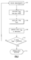
- FIG. 2 illustrates an embodiment of the above described method for detecting a phase to ground fault based on RMS voltage.
- the voltage sensor 60 measures the inverter/conditioner 30 AC input voltage and sends the voltage measurements to the controller 50 (Step 102, Figure 2 ).
- the controller 50 calculates an RMS voltage for each phase (step 104, Figure 2 ).
- the controller 50 calculates a sum of all of the phase voltages for the electrical system and derives its RMS value, referred to as "total Vrms" (step 106, Figure 2 ).
- total Vrms total Vrms
- the controller 50 compares the total RMS voltage value to a threshold value (step 108, Figure 2 ). If the total RMS voltage exceeds the threshold then a phase to ground fault is found (step 110, Figure 2 ). When a phase to ground fault is found, the controller 50 then either takes a predefined action (such as isolating the faulty inverter), or transmits a ground fault detected signal to a second controller 70, which then allows the second controller 70 to take any necessary actions (step 112, Figure 2 ).
- a predefined action such as isolating the faulty inverter
- the RMS voltage value of each phase can be determined by the method illustrated in Figure 3 .
- step 1104 first filters the raw RMS voltage to remove harmonic frequencies (step 1104(a)). The harmonic frequencies are removed because the harmonic frequencies are unnecessary in the determination of the phase RMS voltage, and can cause miscalculations when the phase voltages are summed.
- the filtered RMS voltage is then squared (step 1104(b)) and passed to a second filter.
- the signal is again filtered (step 1104(c)) to remove harmonic frequencies. Since the second filter is after the squaring operation, any harmonics that were too small to be filtered in the first filter step 1104(a) will have been squared and thus are large enough to be filtered by the second filter step 1104(c).
- the signal is then square rooted (step 1104(d)), which returns the signal to its original amplitude without the harmonics.
- the signal is then sent to step 1106 of Figure 3 where the remainder of the method is identical to the method described in the first embodiment, and illustrated in Figure 2 .
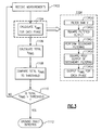
- the total RMS voltage is computed for step 2106 of Figure 5 with the sub-steps illustrated.
- a raw voltage for each phase is received from step 2104 and initially filtered (step 2106(a)).
- the filtered voltages of each phase are then added together (step 2106(b)) and sent to a divider.
- the divider then divides the sum of the phase voltages by the total number of phases in the system (step 2106(c)).
- step 2106(d) the output of the divider is squared (step 2106(d)) in order to make any harmonics that were too small for the first filter (2106(a)) larger.
- the signal is again filtered (step 2106(e)).
- the output of the second filter (step 2106(e)) is square-rooted (step 2106(f)).
- step 2106(g) the total RMS voltage value is output (step 2106(g)) and sent to step 2108 ( Figure 5 ).
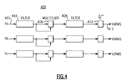
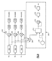
- Figure 6 illustrates a logic circuit 200 for a voltage summer which is capable of performing the steps shown in block 2106 of Figure 5 , and described above.
- the total RMS voltage evaluator 200 accepts a voltage input 206 of all three phases.
- the voltage inputs 206 are then filtered in low pass filters 202 to remove harmonics and leave a cleaner AC signal.
- the filtered voltage signals 232 are then sent to a summer 204.
- the summer 204 combines the filtered voltage signals 232 and outputs a single raw combined voltage signal 234.
- the raw combined 3-phase voltage signal 234 is larger than zero in the event of a ground fault.
- the raw combined voltage signal 234, is sent to a divider 212.
- the divider 212 additionally has a second input 236 equal to K.
- the divider 212 then divides the raw combined voltage by K and outputs a combined voltage value 238.
- the K value for input 236 is the number of phases and may be determined by a signal from the controller 50, the secondary controller 70, predefined within the divider 212, or set using any other known technique.
- harmonics that survived the initial filter 202, and that were introduced as a result of the summer 204 and the divider 212 operations, must be removed from the signal 238.
- the signal 238 is squared (in multiplier block 214), then sent through a filter 218, and then square-rooted (in square-root block 222).
- the square root block 222 outputs a total RMS voltage signal 230 which is in a format that can be accepted and interpreted by the controller 50. These operations remove the minor harmonics in the same manner as described in the second embodiment.
- the output 230 is then passed to step 2108 of Figure 5 .
- Another embodiment of the ground fault detection method combines the phase RMS voltage calculations (step 104, Figure 2 ) with the total RMS voltage calculations (step 106, Figure 2 ), resulting in the method illustrated in Figures 7 , 8 .
- the measurements are filtered (step 502) to remove harmonic frequencies.
- the filtered signals are copied at junction 504 and separate operations are performed on the signals simultaneously (as illustrated in Figure 8 ).
- the first operation, used to calculate phase RMS voltage, of the embodiment of Figure 7 squares the phase RMS voltages (step 506) from junction 504. Then, the RMS voltage signals are again filtered (step 508). After the second filter the signal is combined with the output of the second operation and square rooted (step 510). After being square rooted the voltage signals are output to step 3108 of Figure 7 (step 512).
- the second operation used to calculate total RMS voltage of the embodiment of Figure 7 , sums the filtered signals from junction 504 (step 514).
- the summed signal is then divided by the total number of phases in the system (step 516), and the resulting signal is squared (step 518).
- the signal is again filtered (step 520) and combined with the output of the first operation where the signal is square-rooted (step 510) and output to step 3108 of Figure 7 (step 512).
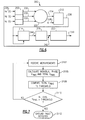
- the logic circuit 400 of Figure 4 is capable of performing step 1104 of the embodiment of Figure 3 .
- the logic circuit initially accepts raw AC phase voltage measurements 402 from the sensor 60 and passes them through a low pass filter 404.
- the signal is then sent to a multiplier 406.
- the multiplier 406 accepts the filtered AC input signal twice and multiplies them together, resulting in a squaring operation.
- the squaring operation additionally squares minor harmonics that were too small to be removed by the initial low-pass filter 404.
- the signal is then sent through a second low-pass filter 408 where the remaining harmonics are removed, resulting in a clean signal that can be properly read by a controller 50. Finally the signal is square rooted in logic block 410, which results in an output signal 412 equal to the phase RMS voltage without additional harmonics. The output signal 412 can then be passed to step 106 of Figure 3 and a total RMS voltage may be calculated based on the output signal 412.
- the Logic Circuit of Figure 9 utilizes a combined first low pass filter 404, and then separates into two separate sub-circuits corresponding to each of the logic circuits 400, 200 of Figures 4 and 6 . These circuits have identical components and operate in the same manner as the logic circuits 200, 400 described above.
Landscapes
- Testing Of Short-Circuits, Discontinuities, Leakage, Or Incorrect Line Connections (AREA)
- Inverter Devices (AREA)
- Control Of Electric Motors In General (AREA)
Applications Claiming Priority (1)
| Application Number | Priority Date | Filing Date | Title |
|---|---|---|---|
| US12/251,499 US20100091419A1 (en) | 2008-10-15 | 2008-10-15 | Motor drive ground fault detection |
Publications (3)
| Publication Number | Publication Date |
|---|---|
| EP2178185A2 true EP2178185A2 (de) | 2010-04-21 |
| EP2178185A3 EP2178185A3 (de) | 2013-10-16 |
| EP2178185B1 EP2178185B1 (de) | 2019-10-09 |
Family
ID=41665590
Family Applications (1)
| Application Number | Title | Priority Date | Filing Date |
|---|---|---|---|
| EP09251412.4A Active EP2178185B1 (de) | 2008-10-15 | 2009-05-28 | Motorgetriebeerdschlusserkennung |
Country Status (2)
| Country | Link |
|---|---|
| US (2) | US20100091419A1 (de) |
| EP (1) | EP2178185B1 (de) |
Cited By (3)
| Publication number | Priority date | Publication date | Assignee | Title |
|---|---|---|---|---|
| US9046560B2 (en) | 2012-06-04 | 2015-06-02 | Eaton Corporation | System and method for high resistance ground fault detection and protection in power distribution systems |
| US9160161B2 (en) | 2012-05-04 | 2015-10-13 | Eaton Corporation | System and method for ground fault detection and protection in adjustable speed drives |
| EP2767839A3 (de) * | 2013-02-18 | 2017-12-20 | LSIS Co., Ltd. | Detektor des quadratischen Mittelwerts und Schalter |
Families Citing this family (7)
| Publication number | Priority date | Publication date | Assignee | Title |
|---|---|---|---|---|
| JP4934703B2 (ja) * | 2009-07-21 | 2012-05-16 | 株式会社日立製作所 | 電力変換装置 |
| WO2015014362A1 (de) * | 2013-08-02 | 2015-02-05 | Schaeffler Technologies Gmbh & Co. Kg | Verfahren zur bestimmung eines fehlers in einem elektronisch kommutierten elektromotor |
| DE102016208960B3 (de) * | 2016-05-24 | 2017-11-09 | Continental Automotive Gmbh | Überwachungsvorrichtung und Verfahren zum Überwachen einer gegenüber einem Referenzpotential galvanisch entkoppelten Wechselspannungsquelle |
| US11881708B2 (en) | 2022-06-09 | 2024-01-23 | Hamilton Sundstrand Corporation | Common mode voltage feed fault protection |
| US12352825B2 (en) | 2022-06-09 | 2025-07-08 | Hamilton Sundstrand Corporation | Common mode voltage feed fault protection |
| US12519412B2 (en) | 2022-06-09 | 2026-01-06 | Hamilton Sundstrand Corporation | Common mode current feed fault protection |
| US12123905B2 (en) | 2022-06-09 | 2024-10-22 | Hamilton Sundstrand Corporation | Common mode current feed fault protection |
Family Cites Families (23)
| Publication number | Priority date | Publication date | Assignee | Title |
|---|---|---|---|---|
| US4525764A (en) * | 1982-06-10 | 1985-06-25 | Titus Charles H | System for disconnecting an electrical power source from a load |
| US4672501A (en) * | 1984-06-29 | 1987-06-09 | General Electric Company | Circuit breaker and protective relay unit |
| US4713608A (en) * | 1986-03-06 | 1987-12-15 | Computer Power Systems Corporation | Apparatus for providing cost efficient power measurement |
| FR2703682B1 (fr) | 1993-04-06 | 1995-05-12 | Atochem Elf Sa | Procédé de préparation de (méth)acrylate(s) d'alkylimidazolidone. |
| JP2543313B2 (ja) * | 1993-06-21 | 1996-10-16 | 光商工株式会社 | 地絡検出装置 |
| EP0652634B1 (de) * | 1993-11-09 | 1999-01-07 | Sanyo Electric Co., Ltd. | Klimaanlage, verwendbar für einen weiten Bereich von Eingangsspannungen |
| US5612601A (en) * | 1993-11-22 | 1997-03-18 | Martin Marietta Energy Systems, Inc. | Method for assessing motor insulation on operating motors |
| US6043664A (en) * | 1997-06-06 | 2000-03-28 | General Electric Company | Method and apparatus for turn fault detection in multi-phase AC motors |
| US6246332B1 (en) * | 1998-11-18 | 2001-06-12 | Abb Power T&D Company Inc. | System and method for detecting voltage and current imbalance in an electrical energy supply |
| US6198613B1 (en) * | 1998-12-23 | 2001-03-06 | Hamilton Sundstrand Corporation | Method and apparatus for distributing alternating electrical current to motors via a direct current bus |
| US6516279B1 (en) * | 2000-05-18 | 2003-02-04 | Rockwell Automation Technologies, Inc. | Method and apparatus for calculating RMS value |
| AU2001270178A1 (en) * | 2000-06-26 | 2002-01-08 | Premier Aviation, Inc. | Method and apparatus for detecting electrical faults and isolating power source from the electrical faults |
| US7016171B2 (en) * | 2001-02-01 | 2006-03-21 | Hydro-Aire, Inc. | Current fault detector and circuit interrupter and packaging thereof |
| US6583975B2 (en) * | 2001-02-01 | 2003-06-24 | Hydro-Aire, Inc. | Aircraft applicable ground fault circuit interrupter |
| GB2412511B (en) * | 2001-06-08 | 2005-11-30 | Eaton Electric Ltd | Measuring devices |
| US6850043B1 (en) * | 2003-01-30 | 2005-02-01 | Hamilton Sundstrand Corporation | Excessive voltage protector for a variable frequency generating system |
| US7254004B2 (en) * | 2003-06-13 | 2007-08-07 | Tdg Aerospace, Inc. | Systems and methods for fault-based power signal interruption |
| US7259477B2 (en) * | 2003-08-15 | 2007-08-21 | American Power Conversion Corporation | Uninterruptible power supply |
| US7215519B2 (en) * | 2003-10-20 | 2007-05-08 | The Boeing Company | Ground and line fault interrupt controller/adapter |
| TWI239133B (en) | 2003-11-12 | 2005-09-01 | Ind Tech Res Inst | A method and a device for rapidly detecting abnormal voltage on a static transfer switch |
| US7272514B2 (en) * | 2005-06-17 | 2007-09-18 | Hamilton Sundstrand Corporation | Protection system for an electrical power generator |
| US7292011B2 (en) * | 2005-08-23 | 2007-11-06 | Hamilton Sundstrand Corporation | Electrical protection of a generator controller |
| FI119212B (fi) * | 2006-12-14 | 2008-08-29 | Abb Oy | Taajuusmuuttajan maasulkusuojaus |
-
2008
- 2008-10-15 US US12/251,499 patent/US20100091419A1/en not_active Abandoned
-
2009
- 2009-05-28 EP EP09251412.4A patent/EP2178185B1/de active Active
-
2011
- 2011-06-30 US US13/173,413 patent/US8305723B2/en active Active
Cited By (3)
| Publication number | Priority date | Publication date | Assignee | Title |
|---|---|---|---|---|
| US9160161B2 (en) | 2012-05-04 | 2015-10-13 | Eaton Corporation | System and method for ground fault detection and protection in adjustable speed drives |
| US9046560B2 (en) | 2012-06-04 | 2015-06-02 | Eaton Corporation | System and method for high resistance ground fault detection and protection in power distribution systems |
| EP2767839A3 (de) * | 2013-02-18 | 2017-12-20 | LSIS Co., Ltd. | Detektor des quadratischen Mittelwerts und Schalter |
Also Published As
| Publication number | Publication date |
|---|---|
| US8305723B2 (en) | 2012-11-06 |
| EP2178185A3 (de) | 2013-10-16 |
| US20110255198A1 (en) | 2011-10-20 |
| EP2178185B1 (de) | 2019-10-09 |
| US20100091419A1 (en) | 2010-04-15 |
Similar Documents
| Publication | Publication Date | Title |
|---|---|---|
| US8305723B2 (en) | Motor drive ground fault detection | |
| US10585134B2 (en) | Method and system for locating ground faults in a network of drives | |
| EP2482411B1 (de) | Laufwerkfehlerschutz | |
| EP2905630B1 (de) | Fehlererkennung in bürstenlosen Erregern | |
| EP1435002B1 (de) | Vorrichtung und verfahren zur berechnung des dreiphasen-leistungsfaktors | |
| KR102738914B1 (ko) | 발전기 모듈에서의 결함 검출 및 분리 | |
| RU2635842C2 (ru) | Двенадцатиимпульсные автотрансформаторные выпрямительные блоки | |
| EP2730023A1 (de) | System zur detektion von internen wicklungsfehlern aufwickeln eines synchronen generators, computerprogrammprodukt und verfahren | |
| JPH11514834A (ja) | 波形歪みのソース判別回路および方法 | |
| KR102900166B1 (ko) | 전동기 감시 장치 및 전동기 감시 방법 | |
| CN103026249B (zh) | 检查永磁发电机和含检测器模块的供电设备的故障的方法 | |
| US8120206B2 (en) | Method of detecting a sustained parallel source condition | |
| EP4290719A1 (de) | Gleichtaktspannungsspeisungsfehlerschutz | |
| US20230400530A1 (en) | Common mode voltage feed fault protection | |
| CN103852669B (zh) | 旋转整流器及励磁电路故障双功能和双余度监测电路 | |
| US4100587A (en) | Circuit for detecting the flow of an excess of reverse power from a load to a power system | |
| EP4290720A1 (de) | Gleichtaktstromspeisungsfehlerschutz | |
| US20230402954A1 (en) | Common mode current feed fault protection | |
| US11262405B2 (en) | Fault detection in a multi-phase electric machine | |
| CN121348159A (zh) | 用于检测接地故障的方法、控制单元和储能系统 | |
| JPS63124970A (ja) | デジタル形フオルトロケ−タ |
Legal Events
| Date | Code | Title | Description |
|---|---|---|---|
| PUAI | Public reference made under article 153(3) epc to a published international application that has entered the european phase |
Free format text: ORIGINAL CODE: 0009012 |
|
| AK | Designated contracting states |
Kind code of ref document: A2 Designated state(s): AT BE BG CH CY CZ DE DK EE ES FI FR GB GR HR HU IE IS IT LI LT LU LV MC MK MT NL NO PL PT RO SE SI SK TR |
|
| AX | Request for extension of the european patent |
Extension state: AL BA RS |
|
| PUAL | Search report despatched |
Free format text: ORIGINAL CODE: 0009013 |
|
| AK | Designated contracting states |
Kind code of ref document: A3 Designated state(s): AT BE BG CH CY CZ DE DK EE ES FI FR GB GR HR HU IE IS IT LI LT LU LV MC MK MT NL NO PL PT RO SE SI SK TR |
|
| AX | Request for extension of the european patent |
Extension state: AL BA RS |
|
| RIC1 | Information provided on ipc code assigned before grant |
Ipc: H02H 3/353 20060101AFI20130910BHEP |
|
| 17P | Request for examination filed |
Effective date: 20140416 |
|
| RBV | Designated contracting states (corrected) |
Designated state(s): AT BE BG CH CY CZ DE DK EE ES FI FR GB GR HR HU IE IS IT LI LT LU LV MC MK MT NL NO PL PT RO SE SI SK TR |
|
| 17Q | First examination report despatched |
Effective date: 20160628 |
|
| STAA | Information on the status of an ep patent application or granted ep patent |
Free format text: STATUS: EXAMINATION IS IN PROGRESS |
|
| GRAP | Despatch of communication of intention to grant a patent |
Free format text: ORIGINAL CODE: EPIDOSNIGR1 |
|
| STAA | Information on the status of an ep patent application or granted ep patent |
Free format text: STATUS: GRANT OF PATENT IS INTENDED |
|
| INTG | Intention to grant announced |
Effective date: 20190423 |
|
| GRAS | Grant fee paid |
Free format text: ORIGINAL CODE: EPIDOSNIGR3 |
|
| GRAA | (expected) grant |
Free format text: ORIGINAL CODE: 0009210 |
|
| STAA | Information on the status of an ep patent application or granted ep patent |
Free format text: STATUS: THE PATENT HAS BEEN GRANTED |
|
| AK | Designated contracting states |
Kind code of ref document: B1 Designated state(s): AT BE BG CH CY CZ DE DK EE ES FI FR GB GR HR HU IE IS IT LI LT LU LV MC MK MT NL NO PL PT RO SE SI SK TR |
|
| REG | Reference to a national code |
Ref country code: GB Ref legal event code: FG4D |
|
| REG | Reference to a national code |
Ref country code: CH Ref legal event code: EP |
|
| REG | Reference to a national code |
Ref country code: IE Ref legal event code: FG4D |
|
| REG | Reference to a national code |
Ref country code: DE Ref legal event code: R096 Ref document number: 602009060065 Country of ref document: DE |
|
| REG | Reference to a national code |
Ref country code: AT Ref legal event code: REF Ref document number: 1189936 Country of ref document: AT Kind code of ref document: T Effective date: 20191115 |
|
| REG | Reference to a national code |
Ref country code: NL Ref legal event code: MP Effective date: 20191009 |
|
| REG | Reference to a national code |
Ref country code: LT Ref legal event code: MG4D |
|
| REG | Reference to a national code |
Ref country code: AT Ref legal event code: MK05 Ref document number: 1189936 Country of ref document: AT Kind code of ref document: T Effective date: 20191009 |
|
| PG25 | Lapsed in a contracting state [announced via postgrant information from national office to epo] |
Ref country code: FI Free format text: LAPSE BECAUSE OF FAILURE TO SUBMIT A TRANSLATION OF THE DESCRIPTION OR TO PAY THE FEE WITHIN THE PRESCRIBED TIME-LIMIT Effective date: 20191009 Ref country code: BG Free format text: LAPSE BECAUSE OF FAILURE TO SUBMIT A TRANSLATION OF THE DESCRIPTION OR TO PAY THE FEE WITHIN THE PRESCRIBED TIME-LIMIT Effective date: 20200109 Ref country code: GR Free format text: LAPSE BECAUSE OF FAILURE TO SUBMIT A TRANSLATION OF THE DESCRIPTION OR TO PAY THE FEE WITHIN THE PRESCRIBED TIME-LIMIT Effective date: 20200110 Ref country code: LV Free format text: LAPSE BECAUSE OF FAILURE TO SUBMIT A TRANSLATION OF THE DESCRIPTION OR TO PAY THE FEE WITHIN THE PRESCRIBED TIME-LIMIT Effective date: 20191009 Ref country code: SE Free format text: LAPSE BECAUSE OF FAILURE TO SUBMIT A TRANSLATION OF THE DESCRIPTION OR TO PAY THE FEE WITHIN THE PRESCRIBED TIME-LIMIT Effective date: 20191009 Ref country code: NL Free format text: LAPSE BECAUSE OF FAILURE TO SUBMIT A TRANSLATION OF THE DESCRIPTION OR TO PAY THE FEE WITHIN THE PRESCRIBED TIME-LIMIT Effective date: 20191009 Ref country code: AT Free format text: LAPSE BECAUSE OF FAILURE TO SUBMIT A TRANSLATION OF THE DESCRIPTION OR TO PAY THE FEE WITHIN THE PRESCRIBED TIME-LIMIT Effective date: 20191009 Ref country code: NO Free format text: LAPSE BECAUSE OF FAILURE TO SUBMIT A TRANSLATION OF THE DESCRIPTION OR TO PAY THE FEE WITHIN THE PRESCRIBED TIME-LIMIT Effective date: 20200109 Ref country code: PL Free format text: LAPSE BECAUSE OF FAILURE TO SUBMIT A TRANSLATION OF THE DESCRIPTION OR TO PAY THE FEE WITHIN THE PRESCRIBED TIME-LIMIT Effective date: 20191009 Ref country code: ES Free format text: LAPSE BECAUSE OF FAILURE TO SUBMIT A TRANSLATION OF THE DESCRIPTION OR TO PAY THE FEE WITHIN THE PRESCRIBED TIME-LIMIT Effective date: 20191009 Ref country code: PT Free format text: LAPSE BECAUSE OF FAILURE TO SUBMIT A TRANSLATION OF THE DESCRIPTION OR TO PAY THE FEE WITHIN THE PRESCRIBED TIME-LIMIT Effective date: 20200210 Ref country code: LT Free format text: LAPSE BECAUSE OF FAILURE TO SUBMIT A TRANSLATION OF THE DESCRIPTION OR TO PAY THE FEE WITHIN THE PRESCRIBED TIME-LIMIT Effective date: 20191009 |
|
| PG25 | Lapsed in a contracting state [announced via postgrant information from national office to epo] |
Ref country code: IS Free format text: LAPSE BECAUSE OF FAILURE TO SUBMIT A TRANSLATION OF THE DESCRIPTION OR TO PAY THE FEE WITHIN THE PRESCRIBED TIME-LIMIT Effective date: 20200224 Ref country code: HR Free format text: LAPSE BECAUSE OF FAILURE TO SUBMIT A TRANSLATION OF THE DESCRIPTION OR TO PAY THE FEE WITHIN THE PRESCRIBED TIME-LIMIT Effective date: 20191009 |
|
| REG | Reference to a national code |
Ref country code: DE Ref legal event code: R097 Ref document number: 602009060065 Country of ref document: DE |
|
| PG2D | Information on lapse in contracting state deleted |
Ref country code: IS |
|
| PG25 | Lapsed in a contracting state [announced via postgrant information from national office to epo] |
Ref country code: DK Free format text: LAPSE BECAUSE OF FAILURE TO SUBMIT A TRANSLATION OF THE DESCRIPTION OR TO PAY THE FEE WITHIN THE PRESCRIBED TIME-LIMIT Effective date: 20191009 Ref country code: EE Free format text: LAPSE BECAUSE OF FAILURE TO SUBMIT A TRANSLATION OF THE DESCRIPTION OR TO PAY THE FEE WITHIN THE PRESCRIBED TIME-LIMIT Effective date: 20191009 Ref country code: RO Free format text: LAPSE BECAUSE OF FAILURE TO SUBMIT A TRANSLATION OF THE DESCRIPTION OR TO PAY THE FEE WITHIN THE PRESCRIBED TIME-LIMIT Effective date: 20191009 Ref country code: CZ Free format text: LAPSE BECAUSE OF FAILURE TO SUBMIT A TRANSLATION OF THE DESCRIPTION OR TO PAY THE FEE WITHIN THE PRESCRIBED TIME-LIMIT Effective date: 20191009 Ref country code: IS Free format text: LAPSE BECAUSE OF FAILURE TO SUBMIT A TRANSLATION OF THE DESCRIPTION OR TO PAY THE FEE WITHIN THE PRESCRIBED TIME-LIMIT Effective date: 20200209 |
|
| PLBE | No opposition filed within time limit |
Free format text: ORIGINAL CODE: 0009261 |
|
| STAA | Information on the status of an ep patent application or granted ep patent |
Free format text: STATUS: NO OPPOSITION FILED WITHIN TIME LIMIT |
|
| PG25 | Lapsed in a contracting state [announced via postgrant information from national office to epo] |
Ref country code: SK Free format text: LAPSE BECAUSE OF FAILURE TO SUBMIT A TRANSLATION OF THE DESCRIPTION OR TO PAY THE FEE WITHIN THE PRESCRIBED TIME-LIMIT Effective date: 20191009 Ref country code: IT Free format text: LAPSE BECAUSE OF FAILURE TO SUBMIT A TRANSLATION OF THE DESCRIPTION OR TO PAY THE FEE WITHIN THE PRESCRIBED TIME-LIMIT Effective date: 20191009 |
|
| 26N | No opposition filed |
Effective date: 20200710 |
|
| PG25 | Lapsed in a contracting state [announced via postgrant information from national office to epo] |
Ref country code: SI Free format text: LAPSE BECAUSE OF FAILURE TO SUBMIT A TRANSLATION OF THE DESCRIPTION OR TO PAY THE FEE WITHIN THE PRESCRIBED TIME-LIMIT Effective date: 20191009 |
|
| PG25 | Lapsed in a contracting state [announced via postgrant information from national office to epo] |
Ref country code: CH Free format text: LAPSE BECAUSE OF NON-PAYMENT OF DUE FEES Effective date: 20200531 Ref country code: LI Free format text: LAPSE BECAUSE OF NON-PAYMENT OF DUE FEES Effective date: 20200531 Ref country code: MC Free format text: LAPSE BECAUSE OF FAILURE TO SUBMIT A TRANSLATION OF THE DESCRIPTION OR TO PAY THE FEE WITHIN THE PRESCRIBED TIME-LIMIT Effective date: 20191009 |
|
| REG | Reference to a national code |
Ref country code: BE Ref legal event code: MM Effective date: 20200531 |
|
| PG25 | Lapsed in a contracting state [announced via postgrant information from national office to epo] |
Ref country code: LU Free format text: LAPSE BECAUSE OF NON-PAYMENT OF DUE FEES Effective date: 20200528 |
|
| PG25 | Lapsed in a contracting state [announced via postgrant information from national office to epo] |
Ref country code: IE Free format text: LAPSE BECAUSE OF NON-PAYMENT OF DUE FEES Effective date: 20200528 |
|
| PG25 | Lapsed in a contracting state [announced via postgrant information from national office to epo] |
Ref country code: BE Free format text: LAPSE BECAUSE OF NON-PAYMENT OF DUE FEES Effective date: 20200531 |
|
| PG25 | Lapsed in a contracting state [announced via postgrant information from national office to epo] |
Ref country code: TR Free format text: LAPSE BECAUSE OF FAILURE TO SUBMIT A TRANSLATION OF THE DESCRIPTION OR TO PAY THE FEE WITHIN THE PRESCRIBED TIME-LIMIT Effective date: 20191009 Ref country code: MT Free format text: LAPSE BECAUSE OF FAILURE TO SUBMIT A TRANSLATION OF THE DESCRIPTION OR TO PAY THE FEE WITHIN THE PRESCRIBED TIME-LIMIT Effective date: 20191009 Ref country code: CY Free format text: LAPSE BECAUSE OF FAILURE TO SUBMIT A TRANSLATION OF THE DESCRIPTION OR TO PAY THE FEE WITHIN THE PRESCRIBED TIME-LIMIT Effective date: 20191009 |
|
| PG25 | Lapsed in a contracting state [announced via postgrant information from national office to epo] |
Ref country code: MK Free format text: LAPSE BECAUSE OF FAILURE TO SUBMIT A TRANSLATION OF THE DESCRIPTION OR TO PAY THE FEE WITHIN THE PRESCRIBED TIME-LIMIT Effective date: 20191009 |
|
| P01 | Opt-out of the competence of the unified patent court (upc) registered |
Effective date: 20230522 |
|
| PGFP | Annual fee paid to national office [announced via postgrant information from national office to epo] |
Ref country code: DE Payment date: 20250423 Year of fee payment: 17 |
|
| PGFP | Annual fee paid to national office [announced via postgrant information from national office to epo] |
Ref country code: GB Payment date: 20250423 Year of fee payment: 17 |
|
| PGFP | Annual fee paid to national office [announced via postgrant information from national office to epo] |
Ref country code: FR Payment date: 20250423 Year of fee payment: 17 |