EP2178227A1 - Récepteur optique pour un système WDM en espace libre - Google Patents
Récepteur optique pour un système WDM en espace libre Download PDFInfo
- Publication number
- EP2178227A1 EP2178227A1 EP08168016A EP08168016A EP2178227A1 EP 2178227 A1 EP2178227 A1 EP 2178227A1 EP 08168016 A EP08168016 A EP 08168016A EP 08168016 A EP08168016 A EP 08168016A EP 2178227 A1 EP2178227 A1 EP 2178227A1
- Authority
- EP
- European Patent Office
- Prior art keywords
- optical
- optical axis
- light beam
- focal plane
- light
- Prior art date
- Legal status (The legal status is an assumption and is not a legal conclusion. Google has not performed a legal analysis and makes no representation as to the accuracy of the status listed.)
- Withdrawn
Links
- 230000003287 optical effect Effects 0.000 title claims abstract description 166
- 238000004891 communication Methods 0.000 title claims abstract description 41
- 230000004075 alteration Effects 0.000 claims abstract description 17
- 230000005855 radiation Effects 0.000 claims description 21
- 230000013011 mating Effects 0.000 claims description 19
- 230000003595 spectral effect Effects 0.000 claims description 16
- 239000011159 matrix material Substances 0.000 claims description 5
- 239000011248 coating agent Substances 0.000 claims description 3
- 238000000576 coating method Methods 0.000 claims description 3
- 238000001228 spectrum Methods 0.000 description 8
- 230000005540 biological transmission Effects 0.000 description 5
- 238000010276 construction Methods 0.000 description 3
- 238000010586 diagram Methods 0.000 description 3
- 239000006185 dispersion Substances 0.000 description 2
- 239000000835 fiber Substances 0.000 description 2
- 230000033590 base-excision repair Effects 0.000 description 1
- 238000006073 displacement reaction Methods 0.000 description 1
- 238000005516 engineering process Methods 0.000 description 1
- 238000000034 method Methods 0.000 description 1
- 239000013307 optical fiber Substances 0.000 description 1
- 239000004065 semiconductor Substances 0.000 description 1
Images

Classifications
-
- G—PHYSICS
- G02—OPTICS
- G02B—OPTICAL ELEMENTS, SYSTEMS OR APPARATUS
- G02B27/00—Optical systems or apparatus not provided for by any of the groups G02B1/00 - G02B26/00, G02B30/00
- G02B27/10—Beam splitting or combining systems
- G02B27/14—Beam splitting or combining systems operating by reflection only
- G02B27/144—Beam splitting or combining systems operating by reflection only using partially transparent surfaces without spectral selectivity
-
- H—ELECTRICITY
- H04—ELECTRIC COMMUNICATION TECHNIQUE
- H04J—MULTIPLEX COMMUNICATION
- H04J14/00—Optical multiplex systems
- H04J14/02—Wavelength-division multiplex systems
-
- G—PHYSICS
- G02—OPTICS
- G02B—OPTICAL ELEMENTS, SYSTEMS OR APPARATUS
- G02B19/00—Condensers, e.g. light collectors or similar non-imaging optics
- G02B19/0004—Condensers, e.g. light collectors or similar non-imaging optics characterised by the optical means employed
- G02B19/0028—Condensers, e.g. light collectors or similar non-imaging optics characterised by the optical means employed refractive and reflective surfaces, e.g. non-imaging catadioptric systems
-
- G—PHYSICS
- G02—OPTICS
- G02B—OPTICAL ELEMENTS, SYSTEMS OR APPARATUS
- G02B19/00—Condensers, e.g. light collectors or similar non-imaging optics
- G02B19/0033—Condensers, e.g. light collectors or similar non-imaging optics characterised by the use
- G02B19/0076—Condensers, e.g. light collectors or similar non-imaging optics characterised by the use for use with a detector
-
- G—PHYSICS
- G02—OPTICS
- G02B—OPTICAL ELEMENTS, SYSTEMS OR APPARATUS
- G02B27/00—Optical systems or apparatus not provided for by any of the groups G02B1/00 - G02B26/00, G02B30/00
- G02B27/10—Beam splitting or combining systems
- G02B27/1006—Beam splitting or combining systems for splitting or combining different wavelengths
-
- G—PHYSICS
- G02—OPTICS
- G02B—OPTICAL ELEMENTS, SYSTEMS OR APPARATUS
- G02B27/00—Optical systems or apparatus not provided for by any of the groups G02B1/00 - G02B26/00, G02B30/00
- G02B27/10—Beam splitting or combining systems
- G02B27/14—Beam splitting or combining systems operating by reflection only
- G02B27/145—Beam splitting or combining systems operating by reflection only having sequential partially reflecting surfaces
-
- H—ELECTRICITY
- H04—ELECTRIC COMMUNICATION TECHNIQUE
- H04B—TRANSMISSION
- H04B10/00—Transmission systems employing electromagnetic waves other than radio-waves, e.g. infrared, visible or ultraviolet light, or employing corpuscular radiation, e.g. quantum communication
- H04B10/11—Arrangements specific to free-space transmission, i.e. transmission through air or vacuum
- H04B10/112—Line-of-sight transmission over an extended range
- H04B10/1121—One-way transmission
Definitions
- the present invention relates to free space optics devices, and more specifically to optical systems for free space optics devices and wireless communication technologies.
- Various communication systems are known for wireless data transmission through the atmosphere, including free space optics devices, in which monochrome (laser) optical transmitters are used, whose radiated light signal carrier is modulated with data and transmitted through the atmosphere to the another free space optics device light optical receiver.
- Optical signals transmission through the atmosphere in free space optics device is provided by device optical transmitters optical systems, forming (collimating) radiated light beams from light transmitters into the narrow light beams turned to another - these light radiation receiving free space optics device, whose receiving optical system collects (focus) light radiation into light receiver surface, what can be single mode or multi-mode fiber optic cable light input surface.
- the focused light is transmitted via optical fibre to the de-multiplexing element, where received light radiation is de-multiplexed (splited up) into received light wave bands.
- the light beam from the communication device's light radiation receiver surface (fiber optic cable input surface) in its passage through de-multiplexing process is geometrical reshaped (recolimated) and focused many times in its way through bandpass filters and de-multiplexing optical elements and received on the wave bands light detectors light radiation sensitive surfaces with significant light radiation losses and high optical noises, which brings to high BERs and limit communication distance.
- the light receiver optical systems with the light detectors light radiation sensitive surfaces in the receiver wave bands in conformable focal planes are installed.
- the free space optics system is known (patent US 7177550B1, publ. 13.02.2007 ) for simultaneous receiving of different lenght light waves signals transmitted through the atmosphere, containing at least one diffractive optical element with screened its central part, which focuses the entering light with various wave length in the various conformable focal points on the diffractive optical element optical axis, various length light waves phase compensator for light waves, befitting light waves from various zones of the diffractive optical element phases indemnification in the conformable focal points, light detectors, each placed near-by or on conformable focal point for light with the certain waves length and the focusing optical element in the entrance of each light detector, light detectors and their focusings optical elements are parallel and collinear of the optical axis of the diffractive optical element.
- the objective of invention is to increase the amount of the simultaneously operating optical channels of the optical device, each of them working on its light wave length to increase communication device joint data transmission rate and decrease the optical noise of each optical channel at receiver side.
- the free space optics communication systems are widely used for wireless data transmission through the atmosphere using monochrome optical transmitters (semiconductor lasers) radiated light beam with light carrier signal modulated with data information and transmitted through atmosphere to other device - optical light signal receiver.
- monochrome optical transmitters semiconductor lasers
- the radiated from laser light carrier waves are modulated with data signals say with radiation intensity, frequency or phase, light carrier waves get polarized accordingly and the light signal received at a receiver side is accordingly demodulated.
- the light radiation intensity is used for signal modulation.
- the term "light” mentioned in description is the optical radiation, what can be either in ultraviolet, visible or infrared range of the electromagnetic waves spectrum.
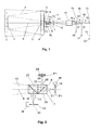
- the offered optical device is created as the achromatic telescopic system with the central screen of input light beam, in the output on its optical axis the block of optical beamsplitter is placed and in the focal plane of the telescopic system on its optical axis a diaphragm is placed. Behind the diaphragm on the optical axis of the telescopic system parallel and coaxial its optical axis a spherical aberration free chromatic component is placed, in whose conformable focal planes of the light radiation spectral lines on its optical axis communication optical channel with conformable spectral line communication sensor optical mating system input is placed.
- the offered optical system enable to unite numerous simultaneouly and independently operating optical communication channels in shared optical system with common optical axis having minimum optical noise level, as from adjacent optical channels, so from the outside radiation.
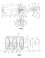
- the offered optical system ( Fig.1 ) consists of the optical system element with a central screen, focal points conformable to the wavelengths of the received light placed on the optical axis of the optical system, with parallel and coaxial placed on optical axis in conformable focal points one after another light sensor optical mating system input elements characterized in that optical system comprise achromatic telescopic system 1 containing convex- plano lense 2, whose flat surface central part 3 is the telescopic system secondary mirror, convex - concave lense 4 with an aperture 5 in the central part of the lense, whose backside has coating 6, what forms the primary mirror of the telescopic system 1 and light beamsplitter block 7, which is placed after the telescopic system last optic element 4 with the block symmetry axis 8 parallel and coaxial to the optical axis 9 of the telescopic system, and who divides the output light beam 10 (see also Fig.2 ) into passing through light beam 11 and deflected light beam 12 or beams (and 13),
- Light beamsplitter block 7 consist of one 26 ( Fig.2 ) or a few (e.g. and 27) separate light beamsplitters, for example, a cube polarized and unpolarized beamsplitter, placed with its symmetry axis 8 parallel and coaxial to the telescopic system optical axis 9 in the outgoing light beam 10.
- the amount of the separate beamsplitters in the beamsplitter block 7 can be more than two.
- the diaphragm 15 is placed, close to or on the telescopic system focal plane F2, behind whom (F2) parallel and coaxial the optical axis 31 the spherical aberration free chromatic component 32 is placed, after which on its optical axis 31 communication device's each optical channel (accordingly 33, 34, 35) with corresponding light radiation spectral line ( ⁇ 4, ⁇ 5, ⁇ 6) on its focal plane F ⁇ 4 , F ⁇ 5 , F ⁇ 6 the channel's with corresponding spectral line ⁇ 4, ⁇ 5, ⁇ 6 communication sensor (accordingly 36, 37, 38) optical mating system input (accordingly 39, 40, 41) is placed.
- the chromatic component 16 (32) ( Fig.4 ) consists of aligned to shared optical axis 9 five lenses: double-convex 42, double-concave 43, double-convex 44, double-concave 45 and double-convex 46.
- the chromatic component 16 (32) can contain also other lens number and their curvature directions.
- the chromatic component 16 (32) ( Fig.5 ) can be different and consists of spherical aberration free achromatic component 47 and diffractive optical component 48 say Fresnel lense.
- the diaphragm 14 ( Fig.2 ) is placed after the light beamsplitter block 7 into through going light beam 11 on telescopic system optical axis 9 close or on the telescopic system focal plane F1 and is fixed in the diaphragm moving mechanism 49 with possible diaphragm linear motion in the optical axis 9 direction.
- the diaphragm 15 is placed behind the light beamsplitter block 7 in the deflected light beam 13 with his optical axis 31 close or on the telescopic system focal plane F2 and is fixed in the diaphragm moving mechanism 50 with possible diaphragm linear motion in the optical axis 31 direction.
- the optical system functions in the following way.
- the light beam entering the telescopic system 1 goes through telescopic system first convex-plano lens 2 and the second concave-convex lens 4, reflects from its (4) back surface coating 6, which forms the telescopic system 1 primary mirror, goes through the concave-convex lens 4 and reflects from the convex-plano lens 2 flat surface central part 3, what is the telescopic system flat secondary mirror, and goes through the aperture 5 in the lens 4 central part.
- light beam 10 goes to the beamsplitter block 7, which is placed with its symmetry axis 8 parallel and coaxial the telescopic system optical axis 9, behind telescopic system last optical element 4.
- the light beam 10 in the beamsplitter block 7 is split into passing through light beam 11 and deflected light beam 12 in the first say polarizing cube beamsplitter 26 (see Fig. 2 ).
- the passing through light beam 11 see Fig.
- the passing through light beam 11 behind the diaphragm 14 goes to parallel and coaxial the telescopic system 1 optical axis 9 placed spherical aberration free chromatic component 16, who consists of aligned to shared optical axis 9 five lenses (see Fig.
- the amount of the optical channels are limited by the communication sensors located one after another on the chromatic component optical axis linear dimensions and the linear chromatic dispersion of the chromatic component - the ability to focus different light spectra lines on different places on the chromatic component optical axis.
- the communication sensor optical mating system input linear dimensions say 0.2 mm and the chromatic component linear chromatic dispersion range on its optical axis say 100 mm/ ⁇ m (say in 1.0 - 1.3 ⁇ m spectra range), more then 10 optical channels can be used.
- the communication sensor can be say light radiation receiver, say PIN diode, as well as the light transmitter say laser or LED, which light sensitive and or lights emitting surface is optical mated with optical channel optical mating system input.
- the light receivers optical interface with the communication channel optical mating system input are sufficient mating input aperture and focused received light image areas at the chromatic component output for all light signal carrier forming spectra lines and the focused received light image area must be lesser than optical mating system input area.
- the communication channel optical mating system input (output) for light transmitter (communication sensor) needs additional angular aperture mating input (output) aperture and chromatic component angular output for all signal carrier forming spectra lines.
- the beamsplitter block 7 (see Fig. 2 ) beamsplitter 26 deflected light beam 12 focuses in telescopic system focal plane F1 on the light beam 12 optical axis 28.
- the video camera matrix (charge-coupled device) 29 with light sensetive element simmetry centre 30 on the optical axis 28 is placed.
- Entering the telescopic system light beam angular shift and direction from the telescopic system optical axis is presented as the image shift on the video camera matrix 29 light sensetive element surface in relation to matrix light sensetive element simmetry centre 30.
- the light beam 12 deviation data from focused light image on the video camera matrix are used for free space optical communication device telescopic system pointing to another - transmitting free space optical communication device.
- the beamsplitter block 7 another beamsplitter 27 deflected light beam 13 focuses on the telescopic system focal plane F2 on its (13) optical axis 31 where diaphragm 15 is placed close or on the telescopic system focal plane F2 (see Fig.
- each optical channel (accordingly say 33, 34, 35) with corresponding radiation spectral line (say ⁇ 4, ⁇ 5, ⁇ 6) on its focal plane F ⁇ 4 , F ⁇ 5 , F ⁇ 6 the channel's with corresponding spectral line ⁇ 4, ⁇ 5, ⁇ 6 communication sensor (accordingly say 36, 37, 38) optical mating system input (accordingly say 39, 40, 41) is placed.
- the beamsplitter block 7 can be placed following one after another beamsplitters, each able to deflect new light beam (see Fig. 3 ) outputed from telescopic system and focus them in their focal planes, limited with their diaphragms, which are placed close or on their focal planes, after which (focal planes) the spherical aberration free chromatic components are placed, in outputs of them light signals are formed for new communication channels.
- the chromatic component 16 (see Fig.5 ) can be different. It consists say of spherical aberration free achromatic component 47 and diffractive optical element 48 whose optical axes are parallel and coaxial telescopic system optical axis 9.
- the chromatic component 16 functions in the following way.
- Passing diaphragm 14 passes through dispersing light beam 11 (see Fig.5 ) goes to spherical aberration free achromatic component 47 input aperture and in the achromatic component 47 output is formed paralell light beam with screened central part (in telescopic system 1), which goes to diffractive optical element 48, say Fresnel lens, what focus light signal carrier forming spectra lines ( ⁇ 1, ⁇ 2, ⁇ 3) on their focal planes F ⁇ 1 , F ⁇ 2 , F ⁇ 3 , where communication sensors optical mating systems inputs are placed.
- diffractive optical element 48 say Fresnel lens
- the diaphragm 14 ( and or 15) (see Fig.2 ) location on the optical axis 9 (and or 31) can be changed, with its displacement mechanism 49 (and or 50) accordingly altering free space optical device's communication channels angular aperture.
Landscapes
- Physics & Mathematics (AREA)
- General Physics & Mathematics (AREA)
- Optics & Photonics (AREA)
- Engineering & Computer Science (AREA)
- Computer Networks & Wireless Communication (AREA)
- Signal Processing (AREA)
- Electromagnetism (AREA)
- Spectroscopy & Molecular Physics (AREA)
- Optical Communication System (AREA)
- Lenses (AREA)
Applications Claiming Priority (1)
| Application Number | Priority Date | Filing Date | Title |
|---|---|---|---|
| LVP-08-177A LV14146B (lv) | 2008-10-20 | 2008-10-20 | Optiskā sistēma gaisa optisko sakaru ierīcei |
Publications (1)
| Publication Number | Publication Date |
|---|---|
| EP2178227A1 true EP2178227A1 (fr) | 2010-04-21 |
Family
ID=40351901
Family Applications (1)
| Application Number | Title | Priority Date | Filing Date |
|---|---|---|---|
| EP08168016A Withdrawn EP2178227A1 (fr) | 2008-10-20 | 2008-10-31 | Récepteur optique pour un système WDM en espace libre |
Country Status (2)
| Country | Link |
|---|---|
| EP (1) | EP2178227A1 (fr) |
| LV (1) | LV14146B (fr) |
Cited By (4)
| Publication number | Priority date | Publication date | Assignee | Title |
|---|---|---|---|---|
| RU2444701C2 (ru) * | 2010-05-28 | 2012-03-10 | Открытое акционерное общество "Центральное конструкторское бюро "Фотон" | Визир-дальномер |
| CN105589191A (zh) * | 2016-02-03 | 2016-05-18 | 中国科学院云南天文台 | 用于调整天文望远镜系统共焦的调焦相机及其调焦方法 |
| WO2016173830A1 (fr) * | 2015-04-27 | 2016-11-03 | Deutsches Zentrum für Luft- und Raumfahrt e.V. | Dispositif optique |
| CN115833989A (zh) * | 2022-11-25 | 2023-03-21 | 东南大学 | 一种基于空间光调制器的波分复用多用户光无线通信系统 |
Citations (7)
| Publication number | Priority date | Publication date | Assignee | Title |
|---|---|---|---|---|
| US5777768A (en) * | 1995-09-01 | 1998-07-07 | Astroterra Corporation | Multiple transmitter laser link |
| EP0876019A2 (fr) * | 1997-04-30 | 1998-11-04 | AT&T Corp. | Récepteur et démultiplexeur optiques pour un système de communication en espace libre par multiplexage en longueurs d'ondes |
| EP1202474A1 (fr) * | 2000-10-05 | 2002-05-02 | Lucent Technologies Inc. | Système de communication optique point à multipoint sans fil en espace libre |
| US7116910B1 (en) * | 2002-04-10 | 2006-10-03 | Terabeam Corporation | Free space optical tap and multi/demultiplexer |
| US7177550B1 (en) | 2001-01-24 | 2007-02-13 | Ball Aerospace & Technologies Corp. | On-axis laser receiver wavelength demultiplexer with integral immersion lensed detectors |
| US20070127926A1 (en) * | 2003-11-17 | 2007-06-07 | Fabio Marioni | Free space optical conditioner |
| US20070242958A1 (en) * | 2005-02-07 | 2007-10-18 | Tomoaki Ieda | Optical Space Transmitter and Optical Space Transmission Method for Wavelength-Multiplexed Light |
-
2008
- 2008-10-20 LV LVP-08-177A patent/LV14146B/lv unknown
- 2008-10-31 EP EP08168016A patent/EP2178227A1/fr not_active Withdrawn
Patent Citations (7)
| Publication number | Priority date | Publication date | Assignee | Title |
|---|---|---|---|---|
| US5777768A (en) * | 1995-09-01 | 1998-07-07 | Astroterra Corporation | Multiple transmitter laser link |
| EP0876019A2 (fr) * | 1997-04-30 | 1998-11-04 | AT&T Corp. | Récepteur et démultiplexeur optiques pour un système de communication en espace libre par multiplexage en longueurs d'ondes |
| EP1202474A1 (fr) * | 2000-10-05 | 2002-05-02 | Lucent Technologies Inc. | Système de communication optique point à multipoint sans fil en espace libre |
| US7177550B1 (en) | 2001-01-24 | 2007-02-13 | Ball Aerospace & Technologies Corp. | On-axis laser receiver wavelength demultiplexer with integral immersion lensed detectors |
| US7116910B1 (en) * | 2002-04-10 | 2006-10-03 | Terabeam Corporation | Free space optical tap and multi/demultiplexer |
| US20070127926A1 (en) * | 2003-11-17 | 2007-06-07 | Fabio Marioni | Free space optical conditioner |
| US20070242958A1 (en) * | 2005-02-07 | 2007-10-18 | Tomoaki Ieda | Optical Space Transmitter and Optical Space Transmission Method for Wavelength-Multiplexed Light |
Non-Patent Citations (1)
| Title |
|---|
| SZAJOWSKI P F ET AL: "KEY ELEMENTS OF HIGH-SPEED WDM TERRESTRIAL FREE-SPACE OPTICAL COMMUNICATIONS SYSTEMS", SPIE PROCEEDINGS,, vol. 3932, 24 January 2000 (2000-01-24), pages 2 - 14, XP000961446, ISSN: 0277-786X * |
Cited By (5)
| Publication number | Priority date | Publication date | Assignee | Title |
|---|---|---|---|---|
| RU2444701C2 (ru) * | 2010-05-28 | 2012-03-10 | Открытое акционерное общество "Центральное конструкторское бюро "Фотон" | Визир-дальномер |
| WO2016173830A1 (fr) * | 2015-04-27 | 2016-11-03 | Deutsches Zentrum für Luft- und Raumfahrt e.V. | Dispositif optique |
| CN105589191A (zh) * | 2016-02-03 | 2016-05-18 | 中国科学院云南天文台 | 用于调整天文望远镜系统共焦的调焦相机及其调焦方法 |
| CN105589191B (zh) * | 2016-02-03 | 2018-04-17 | 中国科学院云南天文台 | 用于调整天文望远镜系统共焦的调焦相机及其调焦方法 |
| CN115833989A (zh) * | 2022-11-25 | 2023-03-21 | 东南大学 | 一种基于空间光调制器的波分复用多用户光无线通信系统 |
Also Published As
| Publication number | Publication date |
|---|---|
| LV14146A (lv) | 2010-04-20 |
| LV14146B (lv) | 2010-06-20 |
Similar Documents
| Publication | Publication Date | Title |
|---|---|---|
| AU2016311179B2 (en) | Free space optical (FSO) system | |
| JP6427869B2 (ja) | 波長選択スイッチ | |
| US10119815B2 (en) | Binocular with integrated laser rangefinder | |
| WO2002004901A1 (fr) | Appareil de controle pour systemes de transmission optique | |
| JP6688442B1 (ja) | 波長可変フィルタ及び光学システム | |
| US7068885B2 (en) | Double diffraction grating planar lightwave circuit | |
| US5838849A (en) | Optical component wherein either an optical field distribution of received light or an optical field distribution of a propagation mode of a receiving waveguide has a double-hump shape | |
| EP2178227A1 (fr) | Récepteur optique pour un système WDM en espace libre | |
| CN101984565B (zh) | 多通道双功能波分复用光电集成模块 | |
| US6829096B1 (en) | Bi-directional wavelength division multiplexing/demultiplexing devices | |
| US6169630B1 (en) | Virtually imaged phased array (VIPA) having lenses arranged to provide a wide beam width | |
| US9804333B1 (en) | Coarse wavelength division multiplexing device | |
| KR102531857B1 (ko) | 일측면 비구면 형상의 마이크로 렌즈 어레이 | |
| CN112526678B (zh) | 一种光谱处理装置以及可重构光分插复用器 | |
| US6766081B2 (en) | Focal length dispersion compensation for field curvature | |
| JP2004271743A (ja) | 光学装置 | |
| US7277607B2 (en) | Optical multiplexer/demultiplexer, optical device, and optical transmission system | |
| US9660681B1 (en) | Tunable optical module for optical communication | |
| JP2003066376A (ja) | 波長分離光学デバイス及び波長多重光伝送モジュール | |
| JP2003066271A (ja) | 光波長分波素子 | |
| WO2019119274A1 (fr) | Spectromètre et système de détection de spectre | |
| US20030086643A1 (en) | Wavelength division multiplexer and wavelength dividing method | |
| CN119805745A (zh) | 光学器件、光学系统及光学设备 | |
| JP4192767B2 (ja) | 光信号処理器製造方法 | |
| KR20230102058A (ko) | 멀티 채널 광학계 |
Legal Events
| Date | Code | Title | Description |
|---|---|---|---|
| PUAI | Public reference made under article 153(3) epc to a published international application that has entered the european phase |
Free format text: ORIGINAL CODE: 0009012 |
|
| AK | Designated contracting states |
Kind code of ref document: A1 Designated state(s): AT BE BG CH CY CZ DE DK EE ES FI FR GB GR HR HU IE IS IT LI LT LU LV MC MT NL NO PL PT RO SE SI SK TR |
|
| AX | Request for extension of the european patent |
Extension state: AL BA MK RS |
|
| 17P | Request for examination filed |
Effective date: 20081104 |
|
| AKX | Designation fees paid |
Designated state(s): AT BE BG CH CY CZ DE DK EE ES FI FR GB GR HR HU IE IS IT LI LT LU LV MC MT NL NO PL PT RO SE SI SK TR |
|
| STAA | Information on the status of an ep patent application or granted ep patent |
Free format text: STATUS: THE APPLICATION IS DEEMED TO BE WITHDRAWN |
|
| 18D | Application deemed to be withdrawn |
Effective date: 20140501 |
|
| REG | Reference to a national code |
Ref country code: DE Ref legal event code: R079 Free format text: PREVIOUS MAIN CLASS: H04B0010100000 Ipc: H04B0010110000 |
|
| REG | Reference to a national code |
Ref country code: DE Ref legal event code: R079 Free format text: PREVIOUS MAIN CLASS: H04B0010100000 Ipc: H04B0010110000 Effective date: 20141001 |