EP2178309A2 - Procédé et dispositif électronique pour commander un transducteur capacitif électro-acoustique - Google Patents
Procédé et dispositif électronique pour commander un transducteur capacitif électro-acoustique Download PDFInfo
- Publication number
- EP2178309A2 EP2178309A2 EP09011184A EP09011184A EP2178309A2 EP 2178309 A2 EP2178309 A2 EP 2178309A2 EP 09011184 A EP09011184 A EP 09011184A EP 09011184 A EP09011184 A EP 09011184A EP 2178309 A2 EP2178309 A2 EP 2178309A2
- Authority
- EP
- European Patent Office
- Prior art keywords
- audio signal
- voltage
- acoustic transducer
- input audio
- capacitance electro
- Prior art date
- Legal status (The legal status is an assumption and is not a legal conclusion. Google has not performed a legal analysis and makes no representation as to the accuracy of the status listed.)
- Granted
Links
Images



Classifications
-
- H—ELECTRICITY
- H03—ELECTRONIC CIRCUITRY
- H03F—AMPLIFIERS
- H03F3/00—Amplifiers with only discharge tubes or only semiconductor devices as amplifying elements
- H03F3/181—Low-frequency amplifiers, e.g. audio preamplifiers
-
- H—ELECTRICITY
- H04—ELECTRIC COMMUNICATION TECHNIQUE
- H04R—LOUDSPEAKERS, MICROPHONES, GRAMOPHONE PICK-UPS OR LIKE ACOUSTIC ELECTROMECHANICAL TRANSDUCERS; ELECTRIC HEARING AIDS; PUBLIC ADDRESS SYSTEMS
- H04R3/00—Circuits for transducers
- H04R3/04—Circuits for transducers for correcting frequency response
- H04R3/06—Circuits for transducers for correcting frequency response of electrostatic transducers
-
- H—ELECTRICITY
- H03—ELECTRONIC CIRCUITRY
- H03F—AMPLIFIERS
- H03F2200/00—Indexing scheme relating to amplifiers
- H03F2200/03—Indexing scheme relating to amplifiers the amplifier being designed for audio applications
-
- H—ELECTRICITY
- H03—ELECTRONIC CIRCUITRY
- H03F—AMPLIFIERS
- H03F2200/00—Indexing scheme relating to amplifiers
- H03F2200/45—Indexing scheme relating to amplifiers the load of the amplifier being a capacitive element, e.g. CRT
-
- H—ELECTRICITY
- H04—ELECTRIC COMMUNICATION TECHNIQUE
- H04R—LOUDSPEAKERS, MICROPHONES, GRAMOPHONE PICK-UPS OR LIKE ACOUSTIC ELECTROMECHANICAL TRANSDUCERS; ELECTRIC HEARING AIDS; PUBLIC ADDRESS SYSTEMS
- H04R19/00—Electrostatic transducers
- H04R19/01—Electrostatic transducers characterised by the use of electrets
- H04R19/013—Electrostatic transducers characterised by the use of electrets for loudspeakers
Definitions
- the present invention relates to an electronic device and a method for driving a capacitance electro-acoustic transducer and according to the pre-characterizing clauses of claims 1 and 10.
- the claimed electronic device includes a capacitance electro-acoustic transducer and an audio driver.
- the audio driver is coupled to the capacitance electro-acoustic transducer.
- the audio driver includes a high-voltage amplifier for receiving an input audio signal and for transforming the input audio signal into an output audio signal to drive the capacitance electro-acoustic transducer, wherein an absolute voltage value of the input audio signal is smaller than an absolute voltage value of the output audio signal.
- the capacitance electro-acoustic transducer can be an electret speaker or an electret earphone, and the capacitance electro-acoustic transducer includes an electret diaphragm and a perforated electrode plate.
- the claimed method for driving a capacitance electro-acoustic transducer includes the steps of: using a high-voltage amplifier to receive an input audio signal and transforming the input audio signal into an output audio signal, wherein an absolute voltage value of the input audio signal is smaller than an absolute voltage value of the output audio signal; and driving the capacitance electro-acoustic transducer according to the output audio signal of the high-voltage amplifier.
- FIG.1 is a diagram of an electronic device 100 for driving a capacitance electro-acoustic transducer according to a first embodiment of the present invention.
- the electronic device 100 includes, but is not limited to, an audio signal source 110, an AC-DC/DC-DC converter 120, an audio driver 130, and a capacitance electro-acoustic transducer 170.
- the audio signal source 110 provides an input audio signal S IN , such as audio signals provided by portable multimedia devices like an MP3 player, a CD player, or a smart phone.
- the audio driver 130 is coupled to the audio signal source 110, the AC-DC/DC-DC converter 120, and the capacitance electro-acoustic transducer 170.
- the audio driver 130 includes a high-voltage amplifier OP1 for receiving the input audio signal S IN and for transforming it into an output audio signal S OUT to drive the capacitance electro-acoustic transducer 170, wherein an absolute voltage value of the input audio signal S IN is smaller than an absolute voltage value of the output audio signal S OUT .
- the input audio signal S IN is substantially 0-3 Vpp
- the output audio signal S OUT is substantially greater than 84 Vpp.
- the AC-DC/DC-DC converter 120 is coupled to the high-voltage amplifier OP1 for converting an AC voltage V AC with 110V-220V or a first DC voltage V DC1 into a second DC voltage V DC2 , wherein the second DC voltage V DC2 is greater than the first DC voltage V DC1.
- the second DC voltage V DC2 acts as a power supply of the high-voltage amplifier OP1.
- the first DC voltage V DC1 is substantially 2.5V-5V
- the second DC voltage V DC2 is substantially 80V-100V.
- the electronic device 100 can be a mobile phone, a game console, or a PDA. But this should not be considered as limitations of the present invention, the electronic device 100 can be a multimedia electronic device of other types.
- the capacitance electro-acoustic transducer 170 can be an electret speaker or an electret earphone, but the present invention is not limited to this only and can be another type of capacitance electro-acoustic transducer.
- the capacitance electro-acoustic transducer 170 includes a perforated electrode plate 180 and an electret diaphragm 190.
- the perforated electrode plate 180 has a plurality of holes 182.
- the input audio signal S IN is a single-ended signal
- the output audio signal S OUT is a pair of differential signals having a first signal S OUT1 and a second signal S OUT2 .
- the present invention is not limited to this only, and the input audio signal S IN can be a single-ended signal or a pair of differential signals and the output audio signal S OUT can be a single-ended signal or a pair of differential signals.
- the perforated electrode plate 180 of the capacitance electro-acoustic transducer 170 receives the first signal S OUT1 of the pair of differential signals and the electret diaphragm 190 of the capacitance electro-acoustic transducer 170 receives the second signal S OUT2 of the pair of differential signals, as is shown in FIG.1 .
- the output audio signal S OUT is a single-ended signal
- the electret diaphragm 190 of the capacitance electro-acoustic transducer 170 receives the single-ended signal and the perforated electrode plate 180 is coupled to the ground (not shown).
- the audio signal source 110 of the electronic device 100 provides the input audio signal S IN (such as 1.68Vpp) to the high-voltage amplifier OP1 of the audio driver 130.
- the AC-DC/DC-DC converter 120 converts the AC voltage V AC with 110V-220V or the first DC voltage V DC1 into the second DC voltage V DC2 (such as 84V), and then provides the second DC voltage V DC2 as a power supply to the high-voltage amplifier OP1.
- the high-voltage amplifier OP1 transforms the input audio signal S IN into the output audio signal S OUT (for example, the first signal S OUT1 is +84Vp and the second signal S OUT2 is -84Vp) to drive the capacitance electro-acoustic transducer 170.
- the high-voltage amplifier OP1 drives the capacitance electro-acoustic transducer 170 with high voltages/low currents.
- FIG.2 is a diagram of an electronic device 200 for driving a capacitance electro-acoustic transducer according to a second embodiment of the present invention.
- the architecture of the electronic device 200 is similar to that of the electronic device 100, and the difference between them is that the electronic device 200 further includes a first low-pass filter 210, an auto gain controller (AGC) 220, and a second low-pass filter 250.
- the first low-pass filter 210 and the auto gain controller 220 are disposed inside the audio driver 230, and the second low-pass filter 250 is coupled between the high-voltage amplifier OP1 and the capacitance electro-acoustic transducer 170.
- the second low-pass filter 250 is coupled to the D class amplifier (i.e. the high-voltage amplifier OP1) for filtering signal components higher than a designated frequency within the output audio signal S OUT .
- the symbol ⁇ r represents a dielectric constant of the vacuum
- the symbol ⁇ 0 represents the relative dielectric constant
- the symbol A represents the area of the capacitor (i.e., the area of the electret diaphragm 190 and the perforated electrode plate 180)
- the symbol d represents the distance between the two ends of the capacitor (i.e., the distance between the electret diaphragm 190 and the perforated electrode plate 180)
- the symbol V static represents the static potential of the static charges located on the electret diaphragm 190.
- the force F of the electret diaphragm 190 is directly proportional to the voltage difference ⁇ V.
- the bandwidth f of the capacitance electro-acoustic transducer 170 can be designed to be smaller than 10 KHz by decreasing the current value I to reduce the power consumption of the capacitance electro-acoustic transducer 170.
- the abovementioned 10 KHz is merely an example for illustrating the present invention, and should not be a limitation of the present invention.
- the bandwidth f of the capacitance electro-acoustic transducer 170 can be designed depending on practical demands.
- the first low-pass filter 210 can be used to limit current or a current-limiting function of the high-voltage amplifier OP1 itself can be used for reducing power consumption.
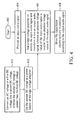
- FIG.4 is a flowchart illustrating a method for driving a capacitance electro-acoustic transducer according an exemplary embodiment of the present invention. Please note that the following steps are not limited to be performed according to the exact sequence shown in FIG.4 if a roughly identical result can be obtained.
- the method includes the following steps:
- the present invention provides a method and a related electronic device for driving the capacitance electro-acoustic transducer with high voltages/low currents.
- the capacitance electro-acoustic transducer 170 if their output sound volumes are the same (such as a stereo of 93-100dB).
- the output sound of the capacitance electro-acoustic transducer 170 is a plane wave, which is different from a spherical wave outputted by the traditional dynamic speaker and can effectively reduce echo to improve the communicating quality of a mobile phone in a speaker mode.
- the capacitance electro-acoustic transducer 170 can be viewed as a capacitor, the bandwidth f is directly proportional to the current value I under a condition that the capacitance C and the voltage difference ⁇ V between the two ends of the capacitor are fixed. Therefore, the bandwidth f of the capacitance electro-acoustic transducer 170 can be determined by using the first low-pass filter 210 to control the current value I.
- the bandwidth f of the capacitance electro-acoustic transducer 170 is lowered to 4KHz to be suitable for the bandwidth of a voice communication of a mobile phone, which can also reduce the power consumption of the audio driver 130 and the capacitance electro-acoustic transducer 170. If the current value I is increased, the bandwidth of the capacitance electro-acoustic transducer 170 can be increased to above 10KHz to be suitable for playing multimedia sound effects, which also keeps perfect sound quality.
Landscapes
- Engineering & Computer Science (AREA)
- Multimedia (AREA)
- Power Engineering (AREA)
- Physics & Mathematics (AREA)
- Acoustics & Sound (AREA)
- Signal Processing (AREA)
- Amplifiers (AREA)
- Circuit For Audible Band Transducer (AREA)
- Control Of Amplification And Gain Control (AREA)
- Electrostatic, Electromagnetic, Magneto- Strictive, And Variable-Resistance Transducers (AREA)
Applications Claiming Priority (1)
| Application Number | Priority Date | Filing Date | Title |
|---|---|---|---|
| TW097139500A TWI484834B (zh) | 2008-10-15 | 2008-10-15 | 驅動一電容式電聲轉換器之方法及電子裝置 |
Publications (3)
| Publication Number | Publication Date |
|---|---|
| EP2178309A2 true EP2178309A2 (fr) | 2010-04-21 |
| EP2178309A3 EP2178309A3 (fr) | 2010-06-02 |
| EP2178309B1 EP2178309B1 (fr) | 2012-05-23 |
Family
ID=41529222
Family Applications (1)
| Application Number | Title | Priority Date | Filing Date |
|---|---|---|---|
| EP09011184A Active EP2178309B1 (fr) | 2008-10-15 | 2009-08-31 | Procédé et dispositif électronique pour commander un transducteur capacitif électro-acoustique |
Country Status (4)
| Country | Link |
|---|---|
| US (1) | US8379882B2 (fr) |
| EP (1) | EP2178309B1 (fr) |
| JP (1) | JP5129196B2 (fr) |
| TW (1) | TWI484834B (fr) |
Cited By (1)
| Publication number | Priority date | Publication date | Assignee | Title |
|---|---|---|---|---|
| EP2775737A1 (fr) * | 2013-03-04 | 2014-09-10 | Sony Corporation | Haut-parleur électrostatique plié |
Families Citing this family (9)
| Publication number | Priority date | Publication date | Assignee | Title |
|---|---|---|---|---|
| US8831253B2 (en) | 2009-10-22 | 2014-09-09 | Industrial Technology Research Institute | Electroacoustic apparatus with optical energy conversion function |
| EP2744103A1 (fr) * | 2012-12-13 | 2014-06-18 | Dialog Semiconductor GmbH | Amplificateur différentiel amplifié classe H |
| DE102015122524A1 (de) * | 2015-12-22 | 2017-06-22 | Sennheiser Electronic Gmbh & Co. Kg | Kopfhörereinheit |
| CN107681993B (zh) * | 2017-09-14 | 2020-10-23 | 维沃移动通信有限公司 | 一种调整音频参数的方法及移动终端 |
| EP3863301B1 (fr) | 2018-10-02 | 2026-05-13 | Audio-Technica Corporation | Dispositif transducteur électro-acoustique électrostatique, circuit de traitement de signal pour transducteur électro-acoustique électrostatique, procédé de traitement de signal et programme de traitement de signal |
| US11387792B2 (en) * | 2019-07-26 | 2022-07-12 | Goertek Inc. | Loudspeaker system and electronics device |
| CN111757207B (zh) * | 2020-07-10 | 2022-04-19 | 菏泽韩升元电子股份有限公司 | 耳机振动组件及具有该振动组件的振动式耳机 |
| CN114978919B (zh) * | 2022-06-14 | 2024-01-09 | 湖南大学 | 利用开关型非福斯特系统的换能器带宽拓宽方法及装置 |
| CN115441962B (zh) * | 2022-09-02 | 2024-06-11 | 湖南大学 | 用于电声换能器的非福斯特宽带匹配控制方法及控制装置 |
Family Cites Families (20)
| Publication number | Priority date | Publication date | Assignee | Title |
|---|---|---|---|---|
| NL8601772A (nl) | 1986-07-08 | 1988-02-01 | Philips Nv | Inrichting voor het omzetten van een elektrisch signaal in een akoestisch signaal, voorzien van een elektrostatische omzettereenheid. |
| FR2695787B1 (fr) * | 1992-09-11 | 1994-11-10 | Suisse Electro Microtech Centr | Transducteur capacitif intégré. |
| JPH06328199A (ja) | 1993-05-24 | 1994-11-29 | Leotec:Kk | 連続的半凝固金属スラリーの製造方法 |
| US6044162A (en) * | 1996-12-20 | 2000-03-28 | Sonic Innovations, Inc. | Digital hearing aid using differential signal representations |
| JP2000139904A (ja) | 1998-11-06 | 2000-05-23 | Kentsu Medico Kk | 音響センサと該音響センサを備えた電子聴診装置 |
| US7319763B2 (en) | 2001-07-11 | 2008-01-15 | American Technology Corporation | Power amplification for parametric loudspeakers |
| US20020141606A1 (en) * | 2001-02-09 | 2002-10-03 | Richard Schweder | Power supply assembly |
| US6621335B2 (en) * | 2001-04-18 | 2003-09-16 | Microsemi Corporation | Class D amplifier with passive RC network |
| JP2004312457A (ja) | 2003-04-08 | 2004-11-04 | Uniden Corp | エコーキャンセル回路、ip電話機及びカールコード |
| JP2005109665A (ja) * | 2003-09-29 | 2005-04-21 | Matsushita Electric Ind Co Ltd | 負荷駆動装置 |
| US7981064B2 (en) | 2005-02-18 | 2011-07-19 | So Sound Solutions, Llc | System and method for integrating transducers into body support structures |
| JP4793174B2 (ja) * | 2005-11-25 | 2011-10-12 | セイコーエプソン株式会社 | 静電型トランスデューサ、回路定数の設定方法 |
| JP4867565B2 (ja) * | 2005-11-29 | 2012-02-01 | セイコーエプソン株式会社 | 容量性負荷の駆動回路、および超音波スピーカ |
| RU2440693C2 (ru) * | 2006-01-03 | 2012-01-20 | Транспарент Саунд Текнолоджи БИ.ВИ.,NL | Электростатические акустические системы и способы |
| CA2844996C (fr) * | 2006-04-14 | 2016-03-08 | Murray R. Harman | Haut-parleur electrostatique a diffusion sonore horizontale et verticale |
| US8208674B2 (en) * | 2006-05-23 | 2012-06-26 | Rh Lyon Corp | Squeeze-stretch driver for earphone and the like |
| WO2008002049A1 (fr) * | 2006-06-28 | 2008-01-03 | Yang Gilsup | Haut-parleur électrostatique à membrane poreuse |
| JP5056360B2 (ja) * | 2006-11-15 | 2012-10-24 | セイコーエプソン株式会社 | D級アンプの制御回路および液体噴射装置、印刷装置 |
| CN201054779Y (zh) * | 2007-06-15 | 2008-04-30 | 财团法人工业技术研究院 | 薄型驻极体静电式扬声器放大装置 |
| EP2215856B1 (fr) * | 2007-11-29 | 2019-02-27 | Hiensch Innovations B.V. | Système de haut-parleur électrostatique |
-
2008
- 2008-10-15 TW TW097139500A patent/TWI484834B/zh active
-
2009
- 2009-05-27 JP JP2009128052A patent/JP5129196B2/ja active Active
- 2009-06-14 US US12/484,243 patent/US8379882B2/en active Active
- 2009-08-31 EP EP09011184A patent/EP2178309B1/fr active Active
Cited By (1)
| Publication number | Priority date | Publication date | Assignee | Title |
|---|---|---|---|---|
| EP2775737A1 (fr) * | 2013-03-04 | 2014-09-10 | Sony Corporation | Haut-parleur électrostatique plié |
Also Published As
| Publication number | Publication date |
|---|---|
| JP5129196B2 (ja) | 2013-01-23 |
| EP2178309B1 (fr) | 2012-05-23 |
| TW201016032A (en) | 2010-04-16 |
| EP2178309A3 (fr) | 2010-06-02 |
| US20100092010A1 (en) | 2010-04-15 |
| US8379882B2 (en) | 2013-02-19 |
| TWI484834B (zh) | 2015-05-11 |
| JP2010098712A (ja) | 2010-04-30 |
Similar Documents
| Publication | Publication Date | Title |
|---|---|---|
| EP2178309B1 (fr) | Procédé et dispositif électronique pour commander un transducteur capacitif électro-acoustique | |
| EP2443744B1 (fr) | Dispositif et procédé pour commander un signal de sortie audio d'un appareil alimenté par batterie | |
| US10171046B2 (en) | System and method for low distortion capacitive signal source amplifier | |
| GB2544822B (en) | Systems and methods for preventing distortion due to supply-based changes in an audio playback system | |
| US9059663B2 (en) | Audio output circuit, electronic device using the same, and audio integrated circuit | |
| JP4535819B2 (ja) | 駆動回路および該駆動回路を備える携帯機器 | |
| US20090285414A1 (en) | Audio processing method and system | |
| CN103858446A (zh) | 用于mems装置的灵敏度调整装置和方法 | |
| WO2011044395A1 (fr) | Système de compensation de défaut de correspondance du signal d'entrée | |
| CN102598503A (zh) | 开启或关闭扬声器的双积分法 | |
| US10756689B2 (en) | Dynamic limiting when driving high capacitive loads | |
| WO2017184458A1 (fr) | Alimentation électrique à variation de signal unique pour une pluralité d'amplificateurs | |
| GB2611947A (en) | Driver circuitry for capacitive transducers | |
| CN201054779Y (zh) | 薄型驻极体静电式扬声器放大装置 | |
| US10524041B1 (en) | Headphone driver and driving method thereof | |
| US20100310098A1 (en) | Electret transducer with solar power | |
| US9008336B2 (en) | Condenser microphone | |
| CN101729962B (zh) | 驱动一电容式电声转换器的方法及电子装置 | |
| US11798978B2 (en) | On-chip inductor with audio headphone amplifier | |
| TW541783B (en) | Audio output amplifier | |
| US20240163607A1 (en) | Dynamic impedance balancing system | |
| CN222940787U (zh) | 放大器芯片、音频组件及电子设备 | |
| EP1973226A1 (fr) | Amplificateur d'alimentation audio et procédé de traitement de signal | |
| EP2512029A1 (fr) | Commande de signal audio pour générateur de son plat | |
| WO2024161100A1 (fr) | Amplificateur à faible bruit |
Legal Events
| Date | Code | Title | Description |
|---|---|---|---|
| PUAI | Public reference made under article 153(3) epc to a published international application that has entered the european phase |
Free format text: ORIGINAL CODE: 0009012 |
|
| 17P | Request for examination filed |
Effective date: 20100215 |
|
| AK | Designated contracting states |
Kind code of ref document: A2 Designated state(s): AT BE BG CH CY CZ DE DK EE ES FI FR GB GR HR HU IE IS IT LI LT LU LV MC MK MT NL NO PL PT RO SE SI SK SM TR |
|
| AX | Request for extension of the european patent |
Extension state: AL BA RS |
|
| PUAL | Search report despatched |
Free format text: ORIGINAL CODE: 0009013 |
|
| AK | Designated contracting states |
Kind code of ref document: A3 Designated state(s): AT BE BG CH CY CZ DE DK EE ES FI FR GB GR HR HU IE IS IT LI LT LU LV MC MK MT NL NO PL PT RO SE SI SK SM TR |
|
| AX | Request for extension of the european patent |
Extension state: AL BA RS |
|
| RIC1 | Information provided on ipc code assigned before grant |
Ipc: H03F 3/181 20060101ALN20100427BHEP Ipc: H04R 19/01 20060101AFI20100427BHEP |
|
| 17Q | First examination report despatched |
Effective date: 20110111 |
|
| REG | Reference to a national code |
Ref country code: DE Ref legal event code: R079 Ref document number: 602009007138 Country of ref document: DE Free format text: PREVIOUS MAIN CLASS: H04R0019000000 Ipc: H04R0003060000 |
|
| GRAP | Despatch of communication of intention to grant a patent |
Free format text: ORIGINAL CODE: EPIDOSNIGR1 |
|
| RIC1 | Information provided on ipc code assigned before grant |
Ipc: H03F 3/181 20060101ALN20120113BHEP Ipc: H04R 19/01 20060101ALI20120113BHEP Ipc: H04R 3/06 20060101AFI20120113BHEP |
|
| GRAS | Grant fee paid |
Free format text: ORIGINAL CODE: EPIDOSNIGR3 |
|
| GRAA | (expected) grant |
Free format text: ORIGINAL CODE: 0009210 |
|
| AK | Designated contracting states |
Kind code of ref document: B1 Designated state(s): AT BE BG CH CY CZ DE DK EE ES FI FR GB GR HR HU IE IS IT LI LT LU LV MC MK MT NL NO PL PT RO SE SI SK SM TR |
|
| REG | Reference to a national code |
Ref country code: GB Ref legal event code: FG4D |
|
| REG | Reference to a national code |
Ref country code: CH Ref legal event code: EP |
|
| REG | Reference to a national code |
Ref country code: AT Ref legal event code: REF Ref document number: 559575 Country of ref document: AT Kind code of ref document: T Effective date: 20120615 |
|
| REG | Reference to a national code |
Ref country code: IE Ref legal event code: FG4D |
|
| REG | Reference to a national code |
Ref country code: DE Ref legal event code: R096 Ref document number: 602009007138 Country of ref document: DE Effective date: 20120719 |
|
| REG | Reference to a national code |
Ref country code: NL Ref legal event code: T3 |
|
| REG | Reference to a national code |
Ref country code: LT Ref legal event code: MG4D Effective date: 20120523 |
|
| PG25 | Lapsed in a contracting state [announced via postgrant information from national office to epo] |
Ref country code: SE Free format text: LAPSE BECAUSE OF FAILURE TO SUBMIT A TRANSLATION OF THE DESCRIPTION OR TO PAY THE FEE WITHIN THE PRESCRIBED TIME-LIMIT Effective date: 20120523 Ref country code: CY Free format text: LAPSE BECAUSE OF FAILURE TO SUBMIT A TRANSLATION OF THE DESCRIPTION OR TO PAY THE FEE WITHIN THE PRESCRIBED TIME-LIMIT Effective date: 20120523 Ref country code: LT Free format text: LAPSE BECAUSE OF FAILURE TO SUBMIT A TRANSLATION OF THE DESCRIPTION OR TO PAY THE FEE WITHIN THE PRESCRIBED TIME-LIMIT Effective date: 20120523 Ref country code: IS Free format text: LAPSE BECAUSE OF FAILURE TO SUBMIT A TRANSLATION OF THE DESCRIPTION OR TO PAY THE FEE WITHIN THE PRESCRIBED TIME-LIMIT Effective date: 20120923 Ref country code: NO Free format text: LAPSE BECAUSE OF FAILURE TO SUBMIT A TRANSLATION OF THE DESCRIPTION OR TO PAY THE FEE WITHIN THE PRESCRIBED TIME-LIMIT Effective date: 20120823 Ref country code: FI Free format text: LAPSE BECAUSE OF FAILURE TO SUBMIT A TRANSLATION OF THE DESCRIPTION OR TO PAY THE FEE WITHIN THE PRESCRIBED TIME-LIMIT Effective date: 20120523 |
|
| REG | Reference to a national code |
Ref country code: AT Ref legal event code: MK05 Ref document number: 559575 Country of ref document: AT Kind code of ref document: T Effective date: 20120523 |
|
| PG25 | Lapsed in a contracting state [announced via postgrant information from national office to epo] |
Ref country code: HR Free format text: LAPSE BECAUSE OF FAILURE TO SUBMIT A TRANSLATION OF THE DESCRIPTION OR TO PAY THE FEE WITHIN THE PRESCRIBED TIME-LIMIT Effective date: 20120523 Ref country code: SI Free format text: LAPSE BECAUSE OF FAILURE TO SUBMIT A TRANSLATION OF THE DESCRIPTION OR TO PAY THE FEE WITHIN THE PRESCRIBED TIME-LIMIT Effective date: 20120523 Ref country code: LV Free format text: LAPSE BECAUSE OF FAILURE TO SUBMIT A TRANSLATION OF THE DESCRIPTION OR TO PAY THE FEE WITHIN THE PRESCRIBED TIME-LIMIT Effective date: 20120523 Ref country code: GR Free format text: LAPSE BECAUSE OF FAILURE TO SUBMIT A TRANSLATION OF THE DESCRIPTION OR TO PAY THE FEE WITHIN THE PRESCRIBED TIME-LIMIT Effective date: 20120824 Ref country code: PT Free format text: LAPSE BECAUSE OF FAILURE TO SUBMIT A TRANSLATION OF THE DESCRIPTION OR TO PAY THE FEE WITHIN THE PRESCRIBED TIME-LIMIT Effective date: 20120924 |
|
| PG25 | Lapsed in a contracting state [announced via postgrant information from national office to epo] |
Ref country code: BE Free format text: LAPSE BECAUSE OF FAILURE TO SUBMIT A TRANSLATION OF THE DESCRIPTION OR TO PAY THE FEE WITHIN THE PRESCRIBED TIME-LIMIT Effective date: 20120523 |
|
| PG25 | Lapsed in a contracting state [announced via postgrant information from national office to epo] |
Ref country code: RO Free format text: LAPSE BECAUSE OF FAILURE TO SUBMIT A TRANSLATION OF THE DESCRIPTION OR TO PAY THE FEE WITHIN THE PRESCRIBED TIME-LIMIT Effective date: 20120523 Ref country code: AT Free format text: LAPSE BECAUSE OF FAILURE TO SUBMIT A TRANSLATION OF THE DESCRIPTION OR TO PAY THE FEE WITHIN THE PRESCRIBED TIME-LIMIT Effective date: 20120523 Ref country code: EE Free format text: LAPSE BECAUSE OF FAILURE TO SUBMIT A TRANSLATION OF THE DESCRIPTION OR TO PAY THE FEE WITHIN THE PRESCRIBED TIME-LIMIT Effective date: 20120523 Ref country code: CZ Free format text: LAPSE BECAUSE OF FAILURE TO SUBMIT A TRANSLATION OF THE DESCRIPTION OR TO PAY THE FEE WITHIN THE PRESCRIBED TIME-LIMIT Effective date: 20120523 Ref country code: SK Free format text: LAPSE BECAUSE OF FAILURE TO SUBMIT A TRANSLATION OF THE DESCRIPTION OR TO PAY THE FEE WITHIN THE PRESCRIBED TIME-LIMIT Effective date: 20120523 Ref country code: DK Free format text: LAPSE BECAUSE OF FAILURE TO SUBMIT A TRANSLATION OF THE DESCRIPTION OR TO PAY THE FEE WITHIN THE PRESCRIBED TIME-LIMIT Effective date: 20120523 |
|
| PG25 | Lapsed in a contracting state [announced via postgrant information from national office to epo] |
Ref country code: PL Free format text: LAPSE BECAUSE OF FAILURE TO SUBMIT A TRANSLATION OF THE DESCRIPTION OR TO PAY THE FEE WITHIN THE PRESCRIBED TIME-LIMIT Effective date: 20120523 |
|
| PG25 | Lapsed in a contracting state [announced via postgrant information from national office to epo] |
Ref country code: MC Free format text: LAPSE BECAUSE OF NON-PAYMENT OF DUE FEES Effective date: 20120831 |
|
| PLBE | No opposition filed within time limit |
Free format text: ORIGINAL CODE: 0009261 |
|
| STAA | Information on the status of an ep patent application or granted ep patent |
Free format text: STATUS: NO OPPOSITION FILED WITHIN TIME LIMIT |
|
| 26N | No opposition filed |
Effective date: 20130226 |
|
| REG | Reference to a national code |
Ref country code: IE Ref legal event code: MM4A |
|
| REG | Reference to a national code |
Ref country code: DE Ref legal event code: R097 Ref document number: 602009007138 Country of ref document: DE Effective date: 20130226 |
|
| PG25 | Lapsed in a contracting state [announced via postgrant information from national office to epo] |
Ref country code: IE Free format text: LAPSE BECAUSE OF NON-PAYMENT OF DUE FEES Effective date: 20120831 Ref country code: BG Free format text: LAPSE BECAUSE OF FAILURE TO SUBMIT A TRANSLATION OF THE DESCRIPTION OR TO PAY THE FEE WITHIN THE PRESCRIBED TIME-LIMIT Effective date: 20120823 |
|
| PG25 | Lapsed in a contracting state [announced via postgrant information from national office to epo] |
Ref country code: ES Free format text: LAPSE BECAUSE OF FAILURE TO SUBMIT A TRANSLATION OF THE DESCRIPTION OR TO PAY THE FEE WITHIN THE PRESCRIBED TIME-LIMIT Effective date: 20120903 |
|
| PG25 | Lapsed in a contracting state [announced via postgrant information from national office to epo] |
Ref country code: MT Free format text: LAPSE BECAUSE OF FAILURE TO SUBMIT A TRANSLATION OF THE DESCRIPTION OR TO PAY THE FEE WITHIN THE PRESCRIBED TIME-LIMIT Effective date: 20120523 |
|
| REG | Reference to a national code |
Ref country code: CH Ref legal event code: PL |
|
| PG25 | Lapsed in a contracting state [announced via postgrant information from national office to epo] |
Ref country code: CH Free format text: LAPSE BECAUSE OF NON-PAYMENT OF DUE FEES Effective date: 20130831 Ref country code: TR Free format text: LAPSE BECAUSE OF FAILURE TO SUBMIT A TRANSLATION OF THE DESCRIPTION OR TO PAY THE FEE WITHIN THE PRESCRIBED TIME-LIMIT Effective date: 20120523 Ref country code: LI Free format text: LAPSE BECAUSE OF NON-PAYMENT OF DUE FEES Effective date: 20130831 |
|
| PG25 | Lapsed in a contracting state [announced via postgrant information from national office to epo] |
Ref country code: SM Free format text: LAPSE BECAUSE OF FAILURE TO SUBMIT A TRANSLATION OF THE DESCRIPTION OR TO PAY THE FEE WITHIN THE PRESCRIBED TIME-LIMIT Effective date: 20120523 Ref country code: LU Free format text: LAPSE BECAUSE OF NON-PAYMENT OF DUE FEES Effective date: 20120831 |
|
| PG25 | Lapsed in a contracting state [announced via postgrant information from national office to epo] |
Ref country code: HU Free format text: LAPSE BECAUSE OF FAILURE TO SUBMIT A TRANSLATION OF THE DESCRIPTION OR TO PAY THE FEE WITHIN THE PRESCRIBED TIME-LIMIT Effective date: 20090831 |
|
| PG25 | Lapsed in a contracting state [announced via postgrant information from national office to epo] |
Ref country code: MK Free format text: LAPSE BECAUSE OF FAILURE TO SUBMIT A TRANSLATION OF THE DESCRIPTION OR TO PAY THE FEE WITHIN THE PRESCRIBED TIME-LIMIT Effective date: 20120523 |
|
| REG | Reference to a national code |
Ref country code: FR Ref legal event code: PLFP Year of fee payment: 8 |
|
| REG | Reference to a national code |
Ref country code: FR Ref legal event code: PLFP Year of fee payment: 9 |
|
| REG | Reference to a national code |
Ref country code: FR Ref legal event code: PLFP Year of fee payment: 10 |
|
| P01 | Opt-out of the competence of the unified patent court (upc) registered |
Effective date: 20230602 |
|
| PGFP | Annual fee paid to national office [announced via postgrant information from national office to epo] |
Ref country code: NL Payment date: 20250704 Year of fee payment: 17 |
|
| PGFP | Annual fee paid to national office [announced via postgrant information from national office to epo] |
Ref country code: DE Payment date: 20250702 Year of fee payment: 17 |
|
| PGFP | Annual fee paid to national office [announced via postgrant information from national office to epo] |
Ref country code: IT Payment date: 20250722 Year of fee payment: 17 |
|
| PGFP | Annual fee paid to national office [announced via postgrant information from national office to epo] |
Ref country code: GB Payment date: 20250703 Year of fee payment: 17 |
|
| PGFP | Annual fee paid to national office [announced via postgrant information from national office to epo] |
Ref country code: FR Payment date: 20250703 Year of fee payment: 17 |