EP2178336A1 - Procédé, dispositif et système de station de base pour une station de base compatible avec un amplificateur monté sur tour à gain élevé - Google Patents
Procédé, dispositif et système de station de base pour une station de base compatible avec un amplificateur monté sur tour à gain élevé Download PDFInfo
- Publication number
- EP2178336A1 EP2178336A1 EP08783805A EP08783805A EP2178336A1 EP 2178336 A1 EP2178336 A1 EP 2178336A1 EP 08783805 A EP08783805 A EP 08783805A EP 08783805 A EP08783805 A EP 08783805A EP 2178336 A1 EP2178336 A1 EP 2178336A1
- Authority
- EP
- European Patent Office
- Prior art keywords
- base station
- tma
- port
- uplink
- signal
- Prior art date
- Legal status (The legal status is an assumption and is not a legal conclusion. Google has not performed a legal analysis and makes no representation as to the accuracy of the status listed.)
- Withdrawn
Links
Images




Classifications
-
- H—ELECTRICITY
- H04—ELECTRIC COMMUNICATION TECHNIQUE
- H04W—WIRELESS COMMUNICATION NETWORKS
- H04W24/00—Supervisory, monitoring or testing arrangements
- H04W24/02—Arrangements for optimising operational condition
-
- H—ELECTRICITY
- H04—ELECTRIC COMMUNICATION TECHNIQUE
- H04W—WIRELESS COMMUNICATION NETWORKS
- H04W88/00—Devices specially adapted for wireless communication networks, e.g. terminals, base stations or access point devices
- H04W88/08—Access point devices
Definitions
- the present invention relates to communication technologies, and in particular, to a method, apparatus, and base station system for making a base station compatible with a high-gain Tower Mounted Amplifier (TMA).
- TMA Tower Mounted Amplifier
- the antenna and feeder components in the base station system are costly, and involve a high cost of installation because they are installed on a tall tower. In the process of adding a new base station, reuse of the antenna and feeder components is important to cost control.
- the TMA is an important antenna and feeder component installed near the antenna on the tower.
- a necessary condition for compatibility between the TMA and the new base station is that the new base station needs to support the gain of the TMA of this model. If the gain of the TMA is beyond the range supported by the new base station, the new base station is not compatible with the TMA.
- the Radio Frequency (RF) front end of a base station that supports a low-gain TMA is suitable only for working with a low-gain (such as 12 dB) TMA. When such an RF front end works with a high-gain TMA, the RF front end of the base station is blocked and the intermodulation is out of specifications. Therefore, the base station that supports the low-gain TMA does not support the high-gain (such as 24 dB or 30 dB) TMA.
- the prior art for solving such a problem is to replace the high-gain TMA with a low-gain TMA.
- the embodiments of the present invention provide a method, apparatus and base station system for making a base station compatible with a high-gain TMA so that the new base station matches the gain of the existing TMA to avoid replacing the existing TMA.
- a method for making a base station compatible with a high-gain TMA includes:
- an apparatus for making a base station compatible with a high-gain TMA includes:
- a base station system provided in an embodiment of the present invention includes a base station and a TMA, and further includes:
- the present invention offers the following benefits:
- the present invention aims to fully use the existing antenna and feeder components to reduce the upgrade cost in the process of upgrading a base station system.
- the first embodiment of the present invention relates to a method for making a base station compatible with a high-gain TMA. As shown in FIG. 1 , the method includes the following steps:
- the uplink signal here refers to the signal sent from a mobile station to a base station.
- the extent of attenuating the uplink signal may be set and adjusted according to the gain of the TMA and the gain supported by the base station. After the signal is attenuated, the gain of the signal falls within the range supported by the base station.
- a signal attenuator may be applied.
- the signal attenuator may be a parameter-variable signal attenuator or a parameter-invariable signal attenuator.
- the signal attenuator here may be realized through a resistor network or a coupler or a filter.
- the method may include the following step:
- the downlink signal here refers to the signal sent from the base station to the mobile station.
- one feeder cable is generally used to transmit both uplink signals and downlink signals simultaneously.
- the downlink signal does not need to be attenuated.
- the downlink signal is forwarded to the TMA directly.
- the foregoing method solves the equipment compatibility problem caused by the TMA gain which exceeds the range supported by the base station, without replacing the TMA.
- the second embodiment of the present invention relates to an apparatus for making a base station compatible with a high-gain TMA. As shown in FIG. 2 , the apparatus includes:
- the first port 201 is connected to the TMA or the feeder (the feeder is applied if a long distance exists between the TMA and the base station), and the second port 205 is connected to the antenna sending/receiving interface of the base station.
- the uplink signal received by the antenna flows along the following path in the apparatus: the first port 201 -> the first uplink signal filter 202 -> the signal attenuator 203 -> the second uplink signal filter 204 -> the second port 205.
- the downlink signal filter 206 exerts outband suppression of the uplink signal.
- the uplink signal that comes in through the first port 201 doesn't bypass the attenuator by entering the downlink signal filter 206. In this way, the uplink signal is attenuated.
- the downlink signal of the base station flows along the following path in the apparatus: the second port 205 -> the downlink signal filter 206 -> the first port 201. In this way, the downlink signal passes through the apparatus smoothly.
- the first uplink signal filter 202 and the second uplink signal filter 204 exert outband suppression of the downlink signal. Therefore, the downlink signal does not enter the attenuator through the uplink signal filter, thus ensuring normal sending of the downlink signal.
- the signal attenuator 203 may be a parameter-invariable signal attenuator or a parameter-variable signal attenuator (which enables adjustment of the relevant parameters of the attenuator according to specific conditions of the TMA and the base station).
- the signal attenuator may be realized through a resistor network or a coupler or a filter.
- the apparatus for making a base station compatible with a TMA in this embodiment may also use the first port 201 to connect the base station, and use the second port 205 to connect the feeder.
- the first port 201 and the second port 205 may use a coaxial cable connector.
- the second embodiment further provides a base station system including an apparatus for making a base station compatible with a high-gain TMA, as shown in FIG. 3 .
- the base station system includes: a TMA 302, a TMA 303, an apparatus 308 for making a base station compatible with a high-gain TMA, an apparatus 309 for making a base station compatible with a high-gain TMA, and a base station 313.
- the base station system includes: an antenna 301, a feeder 304, a feeder 305, a T-connector 306, a T-connector 307, a bypass device 310, and a bypass device 311.
- the two receiving/sending interfaces of the base station 313 are connected to the apparatus 308 and the apparatus 309; the apparatus 308 and the apparatus 309 are connected to the T-connector 306 and the T-connector 307 respectively; the T-connector 306 and the T-connector 307 are connected to the feeder 304 and the feeder 305 respectively; the feeder 304 and the feeder 305 are connected to the TMA 302 and the TMA 303 respectively; the TMA 302 and the TMA 303 are connected to the antenna 301; and the power module 312 of the base station is connected to the T-connectors through the bypass device 311 and the bypass device 310.
- a T-connector here is adapted to: feed the direct current of the base station from a bypass device into a feeder and a TMA, and supply power to the TMA. If the power supply function is integrated into the antenna sending/receiving interface of the base station, an extra T-connector and a capacitor may be added between the apparatus and the sending/receiving interface of the base station. The extra T-connector feeds the direct current out to a bypass device, and the capacitor isolates the direct current for the apparatus.
- the foregoing embodiment is applicable to the scenario where the base station has two sending/receiving interfaces. If the base station has more than two sending/receiving interfaces, for example, 4-way diversity receiving interfaces, the gain of the TMA may be adjusted through four such apparatuses.
- the apparatus in this embodiment may be used to overcome the incompatibility between the new base station and the gain of the existing TMA without modifying the existing TMA and the new base station, thus slashing the upgrade cost.
- the third embodiment of the present invention relates to an apparatus for making a base station compatible with a high-gain TMA.
- the apparatus includes: a downlink signal filter 406, a first uplink signal filter 402, a second uplink signal filter 404 and a signal attenuator 403.
- the downlink signal filter 406 is electrically coupled between a first port 401 and a second port 405 of the apparatus, and is adapted to transmit downlink signals and isolate uplink signals.
- the first uplink signal filter 402 is electrically coupled between the first port 401 and the signal attenuator 403, and is adapted to transmit uplink signals and isolate downlink signals.
- the second uplink signal filter 404 is electrically coupled between the second port 402 and the signal attenuator 403, and is adapted to transmit uplink signals and isolate downlink signals.
- the signal attenuator 403 is electrically coupled between the first uplink signal filter 402 and the second uplink signal filter 404, and is adapted to attenuate uplink signals.
- the apparatus in the third embodiment further includes: a direct current bypass device 407, a first capacitor 408 and a second capacitor 409.
- the direct current bypass device 407 is electrically coupled between the first port 401 and the second port 405, and is adapted to supply power to the TMA.
- the first capacitor 408 is electrically coupled between the first port 401 and a common end of the downlink signal filter 406 and the first uplink signal filter 402, and is adapted to isolate direct current signals.
- the second capacitor 409 is electrically coupled between the second port 405 and a common end of the downlink signal filter 406 and the second uplink signal filter 404, and is adapted to isolate direct current signals.
- a direct current bypass device is added inside the apparatus to implement direct current transmission from the base station to the feeder, and a capacitor is set to isolate direct current.
- the first capacitor 408 and the second capacitor 409 may be distributed parameter capacitors.
- a conductor for transmitting signals may be cut off, and the conductors resulted are separated by a certain distance to short-circuit RF signals, thus a distributed parameter capacitor is realized.
- a direct current bypass device is integrated directly in the apparatus for making a base station compatible with a high-gain TMA in this embodiment. It is adequate to install the apparatus, and an extra direct current bypass device is not needed, thus simplifying the installation.
- the third embodiment further provides a base station system including an apparatus for making a base station compatible with a high-gain TMA, as shown in FIG. 5 .
- the base station system includes: a TMA 502, a TMA 503, an apparatus 506 for making a base station compatible with a high-gain TMA, an apparatus 507 for making a base station compatible with a high-gain TMA, and a base station 508.
- the base station system further includes: an antenna 501, a feeder 504, and a feeder 505.
- the base station in this embodiment has two signal sending/receiving interfaces: one is a main signal sending/receiving interface, and the other is a diversity signal sending/receiving interface, both being able to receive uplink signals and send downlink signals.
- two apparatuses for making a base station compatible with a high-gain TMA are used to adapt the gain for two signal sending/receiving interfaces respectively.
- the base station has more than two signal sending/receiving interfaces, more than two such apparatuses may be configured according to the number of interfaces.
- the fourth embodiment of the present invention relates to an apparatus for making a base station compatible with a high-gain TMA, as shown in FIG. 6 .
- this embodiment integrates two apparatuses for making a base station compatible with a high-gain TMA into one entity, thus saving the materials for manufacturing the apparatuses.
- more than two apparatuses may be integrated into one entity according to the specific conditions.
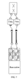
- FIG. 7 shows a base station system including such an apparatus for making a base station compatible with a high-gain TMA.
- the fifth embodiment of the present invention relates to apparatuses for making a base station compatible with a high-gain TMA, as shown in FIG. 8 .
- one of the apparatuses does not include any filter; instead, the apparatus uses an attenuator to attenuate uplink signals directly.
- This design is applicable when some signal sending/receiving interfaces in the base station have no downlink signal, and saves the cost of manufacturing the apparatus.
- other different designs are also applicable. For example, if the base station has 4-way diversity receiving interfaces (three interfaces are incapable of transmitting downlink signals), the filter may be removed from the apparatuses for three of the diversity receiving interfaces to save costs.
- FIG. 9 shows a base station system including such an apparatus for making a base station compatible with a high-gain TMA.
- the base station has one sector. If the base station to be upgraded has multiple sectors, similar methods and apparatuses may be applied to each sector to make the base station compatible with the high-gain TMA.
- the apparatus for making a base station compatible with a high-gain TMA in the embodiments may be used to overcome the incompatibility between the new base station and the gain of the existing TMA without modifying the existing TMA and the new base station, and avoid the expenditure of purchasing a new TMA. Because it is not necessary to climb the tower to replace the existing TMA, massive labor costs are saved, and the cost and the difficulty of the upgrade are reduced drastically on the whole.
Landscapes
- Engineering & Computer Science (AREA)
- Computer Networks & Wireless Communication (AREA)
- Signal Processing (AREA)
- Mobile Radio Communication Systems (AREA)
- Input Circuits Of Receivers And Coupling Of Receivers And Audio Equipment (AREA)
Applications Claiming Priority (2)
| Application Number | Priority Date | Filing Date | Title |
|---|---|---|---|
| CNA2007100773917A CN101141714A (zh) | 2007-09-26 | 2007-09-26 | 一种基站兼容高增益塔顶放大器的方法和装置 |
| PCT/CN2008/071812 WO2009039738A1 (fr) | 2007-09-26 | 2008-07-30 | Procédé, dispositif et système de station de base pour une station de base compatible avec un amplificateur monté sur tour à gain élevé |
Publications (2)
| Publication Number | Publication Date |
|---|---|
| EP2178336A1 true EP2178336A1 (fr) | 2010-04-21 |
| EP2178336A4 EP2178336A4 (fr) | 2011-01-19 |
Family
ID=39193402
Family Applications (1)
| Application Number | Title | Priority Date | Filing Date |
|---|---|---|---|
| EP08783805A Withdrawn EP2178336A4 (fr) | 2007-09-26 | 2008-07-30 | Procédé, dispositif et système de station de base pour une station de base compatible avec un amplificateur monté sur tour à gain élevé |
Country Status (3)
| Country | Link |
|---|---|
| EP (1) | EP2178336A4 (fr) |
| CN (1) | CN101141714A (fr) |
| WO (1) | WO2009039738A1 (fr) |
Cited By (2)
| Publication number | Priority date | Publication date | Assignee | Title |
|---|---|---|---|---|
| CN102946269A (zh) * | 2012-11-15 | 2013-02-27 | 哈尔滨海能达科技有限公司 | 控制塔顶放大器增益的方法、系统、塔顶放大器及基站 |
| EP3553954A4 (fr) * | 2016-12-29 | 2020-01-15 | Huawei Technologies Co., Ltd. | Procédé de suppression d'intermodulation passive et système de suppression d'intermodulation passive |
Families Citing this family (4)
| Publication number | Priority date | Publication date | Assignee | Title |
|---|---|---|---|---|
| CN101141714A (zh) * | 2007-09-26 | 2008-03-12 | 华为技术有限公司 | 一种基站兼容高增益塔顶放大器的方法和装置 |
| CN105763220B (zh) | 2011-06-01 | 2021-03-05 | 康普技术有限责任公司 | 具有非双工器隔离子系统的宽带分布式天线系统 |
| CN111556378B (zh) * | 2020-04-24 | 2022-05-27 | 泉州凯佳新材料研究院有限公司 | 一种卫星通信基站信号塔防辐射装置 |
| CN117544193B (zh) * | 2023-11-10 | 2024-08-02 | 北京唯得科技有限公司 | 一种塔顶放大器、通讯系统及通讯系统运行方法 |
Family Cites Families (5)
| Publication number | Priority date | Publication date | Assignee | Title |
|---|---|---|---|---|
| JP3576758B2 (ja) * | 1997-07-07 | 2004-10-13 | 株式会社日立国際電気 | 周波数変換形中継増幅装置 |
| AU2003219940C1 (en) * | 2003-02-26 | 2010-03-04 | Andrew Corporation | Cellular signal enhancer |
| US7738853B2 (en) * | 2004-10-29 | 2010-06-15 | Antone Wireless Corporation | Low noise figure radiofrequency device |
| CN2862541Y (zh) * | 2005-11-30 | 2007-01-24 | 李学军 | 多载波基站放大器 |
| CN101141714A (zh) * | 2007-09-26 | 2008-03-12 | 华为技术有限公司 | 一种基站兼容高增益塔顶放大器的方法和装置 |
-
2007
- 2007-09-26 CN CNA2007100773917A patent/CN101141714A/zh active Pending
-
2008
- 2008-07-30 EP EP08783805A patent/EP2178336A4/fr not_active Withdrawn
- 2008-07-30 WO PCT/CN2008/071812 patent/WO2009039738A1/fr not_active Ceased
Cited By (3)
| Publication number | Priority date | Publication date | Assignee | Title |
|---|---|---|---|---|
| CN102946269A (zh) * | 2012-11-15 | 2013-02-27 | 哈尔滨海能达科技有限公司 | 控制塔顶放大器增益的方法、系统、塔顶放大器及基站 |
| EP3553954A4 (fr) * | 2016-12-29 | 2020-01-15 | Huawei Technologies Co., Ltd. | Procédé de suppression d'intermodulation passive et système de suppression d'intermodulation passive |
| US10574280B2 (en) | 2016-12-29 | 2020-02-25 | Huawei Technologies Co., Ltd. | Passive intermodulation suppression method and passive intermodulation suppression system |
Also Published As
| Publication number | Publication date |
|---|---|
| EP2178336A4 (fr) | 2011-01-19 |
| CN101141714A (zh) | 2008-03-12 |
| WO2009039738A1 (fr) | 2009-04-02 |
Similar Documents
| Publication | Publication Date | Title |
|---|---|---|
| EP2159933B1 (fr) | Réglage d'amplificateurs dans un système distribué d'antennes | |
| EP1025615B1 (fr) | Unites tetes de mat autonomes pour reseaux de communications cellulaires | |
| EP2178336A1 (fr) | Procédé, dispositif et système de station de base pour une station de base compatible avec un amplificateur monté sur tour à gain élevé | |
| US9179501B2 (en) | Multi-carrier integration apparatus for distributed antenna system | |
| US6738597B1 (en) | Repeating installation using telephone line | |
| CN102711151B (zh) | 智能数字无线直放站的控制方法及智能数字无线直放站 | |
| US7466990B2 (en) | Intelligent multiplexers in an antenna line management system | |
| CN102377027A (zh) | 一种有源天线及校准有源天线的方法 | |
| CN102355296A (zh) | 一种用于同频中继器的干扰抵消系统及方法 | |
| US6925312B2 (en) | Sharing of antennas by base station nodes of telecommunications network | |
| CN101197468B (zh) | 一种天线和一种基站系统 | |
| CN103187985B (zh) | 一种通信设备和通信系统 | |
| EP2660975A1 (fr) | Amplificateur monté sur pylône et son procédé d'utilisation | |
| EP3756416B1 (fr) | Ensemble de téléphonie mobile hétérogène permettant d'alimenter au moins une cellule de téléphonie mobile avec des services de téléphonie mobile | |
| CN203942528U (zh) | 一种无线覆盖增强设备 | |
| CN116233925B (zh) | 通信控制方法、系统、时延调整装置及存储介质 | |
| CN102356515A (zh) | 具有可置换功率放大器的发射机 | |
| CN112437482B (zh) | 一种tdd通信设备、tdd通信系统及功率调整方法 | |
| CN102291747A (zh) | 支持塔顶放大器的基站系统及其实现方法 | |
| US20100113096A1 (en) | Aerial system, in particular mobile communication aerial system, and associated transmission and control device | |
| CN218587179U (zh) | 一种双频段耦合收容箱 | |
| KR101227023B1 (ko) | 이중화 모듈을 갖는 rf 중계기 | |
| CN111585585B (zh) | 一种实现天线Ping功能的装置及方法 | |
| KR100484071B1 (ko) | 기지국에서의 광중계 제어 장치 | |
| KR20060032934A (ko) | 타임디비젼 듀플렉싱 무선통신시스템용 광중계기 |
Legal Events
| Date | Code | Title | Description |
|---|---|---|---|
| PUAI | Public reference made under article 153(3) epc to a published international application that has entered the european phase |
Free format text: ORIGINAL CODE: 0009012 |
|
| 17P | Request for examination filed |
Effective date: 20100310 |
|
| AK | Designated contracting states |
Kind code of ref document: A1 Designated state(s): AT BE BG CH CY CZ DE DK EE ES FI FR GB GR HR HU IE IS IT LI LT LU LV MC MT NL NO PL PT RO SE SI SK TR |
|
| AX | Request for extension of the european patent |
Extension state: AL BA MK RS |
|
| DAX | Request for extension of the european patent (deleted) | ||
| A4 | Supplementary search report drawn up and despatched |
Effective date: 20101221 |
|
| 17Q | First examination report despatched |
Effective date: 20110914 |
|
| STAA | Information on the status of an ep patent application or granted ep patent |
Free format text: STATUS: THE APPLICATION IS DEEMED TO BE WITHDRAWN |
|
| 18D | Application deemed to be withdrawn |
Effective date: 20130326 |