EP2178443B1 - Medizinische Vorrichtung zur Verwendung in der Gewebecharakterisierung und Behandlung - Google Patents
Medizinische Vorrichtung zur Verwendung in der Gewebecharakterisierung und Behandlung Download PDFInfo
- Publication number
- EP2178443B1 EP2178443B1 EP08776603.6A EP08776603A EP2178443B1 EP 2178443 B1 EP2178443 B1 EP 2178443B1 EP 08776603 A EP08776603 A EP 08776603A EP 2178443 B1 EP2178443 B1 EP 2178443B1
- Authority
- EP
- European Patent Office
- Prior art keywords
- tissue
- carrier
- treatment tool
- along
- sensors
- Prior art date
- Legal status (The legal status is an assumption and is not a legal conclusion. Google has not performed a legal analysis and makes no representation as to the accuracy of the status listed.)
- Not-in-force
Links
- 238000012512 characterization method Methods 0.000 title claims description 33
- 230000002159 abnormal effect Effects 0.000 claims description 19
- 239000000523 sample Substances 0.000 claims description 12
- 238000001574 biopsy Methods 0.000 claims description 5
- 229940079593 drug Drugs 0.000 claims description 3
- 239000003814 drug Substances 0.000 claims description 3
- 238000000034 method Methods 0.000 description 8
- 230000002093 peripheral effect Effects 0.000 description 2
- 238000002604 ultrasonography Methods 0.000 description 2
- 206010028980 Neoplasm Diseases 0.000 description 1
- 238000004458 analytical method Methods 0.000 description 1
- 210000000481 breast Anatomy 0.000 description 1
- 238000010276 construction Methods 0.000 description 1
- 230000008602 contraction Effects 0.000 description 1
- 230000001747 exhibiting effect Effects 0.000 description 1
- 238000011065 in-situ storage Methods 0.000 description 1
- 230000010354 integration Effects 0.000 description 1
- 238000004519 manufacturing process Methods 0.000 description 1
- 230000003287 optical effect Effects 0.000 description 1
- 230000002250 progressing effect Effects 0.000 description 1
- 230000008054 signal transmission Effects 0.000 description 1
- 239000000126 substance Substances 0.000 description 1
Images


Classifications
-
- A—HUMAN NECESSITIES
- A61—MEDICAL OR VETERINARY SCIENCE; HYGIENE
- A61B—DIAGNOSIS; SURGERY; IDENTIFICATION
- A61B10/00—Instruments for taking body samples for diagnostic purposes; Other methods or instruments for diagnosis, e.g. for vaccination diagnosis, sex determination or ovulation-period determination; Throat striking implements
- A61B10/02—Instruments for taking cell samples or for biopsy
- A61B10/0233—Pointed or sharp biopsy instruments
-
- A—HUMAN NECESSITIES
- A61—MEDICAL OR VETERINARY SCIENCE; HYGIENE
- A61B—DIAGNOSIS; SURGERY; IDENTIFICATION
- A61B10/00—Instruments for taking body samples for diagnostic purposes; Other methods or instruments for diagnosis, e.g. for vaccination diagnosis, sex determination or ovulation-period determination; Throat striking implements
- A61B10/02—Instruments for taking cell samples or for biopsy
- A61B10/0233—Pointed or sharp biopsy instruments
- A61B10/0266—Pointed or sharp biopsy instruments means for severing sample
-
- A—HUMAN NECESSITIES
- A61—MEDICAL OR VETERINARY SCIENCE; HYGIENE
- A61B—DIAGNOSIS; SURGERY; IDENTIFICATION
- A61B17/00—Surgical instruments, devices or methods
- A61B2017/00017—Electrical control of surgical instruments
- A61B2017/00022—Sensing or detecting at the treatment site
-
- A—HUMAN NECESSITIES
- A61—MEDICAL OR VETERINARY SCIENCE; HYGIENE
- A61B—DIAGNOSIS; SURGERY; IDENTIFICATION
- A61B17/00—Surgical instruments, devices or methods
- A61B2017/00017—Electrical control of surgical instruments
- A61B2017/00115—Electrical control of surgical instruments with audible or visual output
- A61B2017/00128—Electrical control of surgical instruments with audible or visual output related to intensity or progress of surgical action
-
- A—HUMAN NECESSITIES
- A61—MEDICAL OR VETERINARY SCIENCE; HYGIENE
- A61B—DIAGNOSIS; SURGERY; IDENTIFICATION
- A61B17/00—Surgical instruments, devices or methods
- A61B2017/00017—Electrical control of surgical instruments
- A61B2017/00199—Electrical control of surgical instruments with a console, e.g. a control panel with a display
-
- A—HUMAN NECESSITIES
- A61—MEDICAL OR VETERINARY SCIENCE; HYGIENE
- A61B—DIAGNOSIS; SURGERY; IDENTIFICATION
- A61B18/00—Surgical instruments, devices or methods for transferring non-mechanical forms of energy to or from the body
- A61B18/04—Surgical instruments, devices or methods for transferring non-mechanical forms of energy to or from the body by heating
- A61B18/12—Surgical instruments, devices or methods for transferring non-mechanical forms of energy to or from the body by heating by passing a current through the tissue to be heated, e.g. high-frequency current
- A61B18/14—Probes or electrodes therefor
- A61B2018/1475—Electrodes retractable in or deployable from a housing
-
- A—HUMAN NECESSITIES
- A61—MEDICAL OR VETERINARY SCIENCE; HYGIENE
- A61B—DIAGNOSIS; SURGERY; IDENTIFICATION
- A61B90/00—Instruments, implements or accessories specially adapted for surgery or diagnosis and not covered by any of the groups A61B1/00 - A61B50/00, e.g. for luxation treatment or for protecting wound edges
- A61B90/06—Measuring instruments not otherwise provided for
- A61B2090/061—Measuring instruments not otherwise provided for for measuring dimensions, e.g. length
-
- A—HUMAN NECESSITIES
- A61—MEDICAL OR VETERINARY SCIENCE; HYGIENE
- A61B—DIAGNOSIS; SURGERY; IDENTIFICATION
- A61B5/00—Measuring for diagnostic purposes; Identification of persons
-
- A—HUMAN NECESSITIES
- A61—MEDICAL OR VETERINARY SCIENCE; HYGIENE
- A61B—DIAGNOSIS; SURGERY; IDENTIFICATION
- A61B90/00—Instruments, implements or accessories specially adapted for surgery or diagnosis and not covered by any of the groups A61B1/00 - A61B50/00, e.g. for luxation treatment or for protecting wound edges
- A61B90/36—Image-producing devices or illumination devices not otherwise provided for
- A61B90/37—Surgical systems with images on a monitor during operation
Definitions
- This invention relates to medical devices for use in tissue characterization and treatment.
- Such techniques include those utilizing determination of the electrical properties of a tissue, for example, by determination of electrical impedance or dielectric constants. Some kinds of tumors can be identified by determining differences in the measured electrical properties of the tissue. The identified and located region of abnormal tissue can then be treated and/or removed from the body
- tissue characterization sensor and its integration with a tissue treatment/removal tool are described in the following patent publications, all assigned to the assignee of the present application: US2003138378 , WO2006103665 , WO2007015255 , US6813515 and US7184824 .
- US 6,689,145 discloses a biopsy system that includes a transducer, preferably an ultrasound sensor that may have a linear array of ultrasound transducers. Said document however fails to indicate any distances between the transducers in the array, and the sensor used in US 6,689,145 is neither configured for nor capable of dynamically scanning tissue, along a scanning axis when and if the device is progressed inside the tissue along its longitudinal axis.
- Said reference neither teaches nor suggests use of data generated by the array of transducers for determining an exact dimension of an abnormal tissue along a scanning axis, and it specifically does not disclose any control unit configured and operable for receiving and analyzing the tissue characterization signals from each of all the sensors while at successive locations thereof along the scanning axis, and utilizing data indicative of said known distances between the respective sensors, and determining a dimension of an abnormal tissue specimen inside said tissue mass.
- tissue specimen e.g. abnormal tissues
- tissue treatment technique capable of adjusting a treatment volume to the determined volume of the abnormal tissue specimen.
- the present invention provides a system for use in tissue characterization and treatment as defined in independent claim 1.
- This system comprises a medical device and a control unit connectable thereto.
- the medical device comprises a tissue characterization probe comprising a carrier which comprises tissue characterization sensors.
- Each of the tissue characterization sensors is configured and operable to generate a tissue characterization signal.
- the carrier is an elongated carrier exhibiting a longitudinal axis and is configured for carrying a treatment tool.
- the tissue characterization sensors are arranged in an array along the longitudinal axis in a spaced-apart relationship with known distances between them at least along the longitudinal axis of the carrier such that during progression of the probe through a tissue mass along a scanning axis - which is the longitudinal axis - each of the sensors generates the tissue characterization signals from their successive locations along the scanning axis.
- the system is characterized in that the control unit is configured and operable for receiving and analyzing the tissue characterization signals from each of all the sensors while at successive locations thereof along the scanning axis. It also utilizes data indicative of the known distances between the respective sensors for determining a dimension of an abnormal tissue specimen inside the tissue mass based on the continuously received characterization signals from the successive locations of the sensors in the array.
- the distances between the tissue characterization sensors in the array are either equal or not.
- the elongated carrier carries a treatment tool.
- the treatment tool has at least one tissue treating portion and wherein said treatment tool is configured and operable to be selectively shiftable between its inoperative position being located substantially entirely inside the carrier and its operative position projecting by its at least one tissue treating portion towards outside the carrier.
- the treatment tool may also be configured and operable with a variable dimension of the at least one tissue treating portion projectable from the carrier.
- the tissue treating portion of the treatment tool is movable with respect to the carrier along the axis.
- the treatment tool may also be configured for carrying out at least one of the following: biopsy, cutting, delivering physical treatment, delivering treatment medication, diagnostics.
- the tissue treating portion is configured as a tissue excision element.
- the at least one excision element comprises a tissue collecting unit for collecting tissue being removed.
- the treatment tool comprises a body and at least one excision element projectable from said body. More preferably, the excision element extends between its first and second ends which are attached to respective first and second locations on the treatment tool body and are spaced-apart from one another along the axis of said carrier. Even more preferably, the treatment tool body extends along at least a part of the carrier thereinside such that at least one of the first and second locations is movable towards and away from the other along said axis of the carrier to thereby adjust the dimension of a portion of the excision element projecting from the carrier.
- the treatment tool is for treating the abnormal tissue specimen, the treatment tool being configured and operable to be selectively shiftable between its inoperative position being located substantially entirely inside said carrier and its operative position projecting by its at least one tissue treating portion towards outside the carrier.
- the treatment tool is configured for removing the abnormal tissue specimen, and the treatment tool is configured and operable to be selectively shiftable between its inoperative position being located substantially entirely inside said carrier and its operative position projecting by at least a part of its at least one excision element towards outside the carrier.
- the treatment tool is configured for removing the abnormal tissue specimen, and the treatment tool has a body extending inside at least a part of the carrier and at least one excision element, said at least one excision element being selectively projectable from the body towards outside the carrier and having variable dimension of its projecting portion.
- a medical device generally designated 10 .
- the device 10 is configured for use in tissue characterization and treatment, and includes a tissue characterization probe 12 carried by an elongated shaft 14, which has distal and proximal ends 14A and 14B, respectively, and is formed with a control handle 15 at its proximal end 14B.
- the tissue characterization probe 12 includes an array of tissue characterization sensors, eight such sensors S 1 -S 8 being shown in the present example.
- the tissue characterization sensor array may include one or more of optical, radiofrequency (RF), microwave (MW), electrical, magnetic, temperature, elastic, biological, chemical, radioactive-emission, and mechanical sensors of any known type.
- RF radiofrequency
- MW microwave
- electrical magnetic
- temperature temperature
- elastic elastic
- biological biological
- chemical radioactive-emission
- mechanical sensors of any known type.
- the construction and operation of the tissue characterization sensor does not form part of the present invention, and therefore need not be specifically described.
- sensors described in the above indicated patent publications assigned to the assignee of the present application may be used.
- the sensors S 1 -S 8 are arranged in a spaced-apart relationship along a longitudinal axis LA of the carrier 14, and may be arranged in one- or two dimensional array.
- the sensor array may include, in addition to a group of sensors arranged in one-dimensional array, sensors arranged in a spaced-apart manner along a circumferential region of the carrier.
- the sensor array gives, in real time, indication about the nature of tissue along the carrier 14.
- the sensors are spaced along the axis LA from one another a known distance, which may or may not be equal for all the sensors in the array.
- the known relative locations of the sensors along the carrier 12 allows for identifying corresponding locations in a tissue mass when the probe is progressing through the tissue mass (i.e. scans the tissue) based on signals received from the sensors.
- the medical device 10 is associated with an appropriate control system 19 configured for receiving and analyzing the signals generated by the sensors. It should be understood that connection between the sensors and the control unit is shown in the figure schematically, and in case wired connection is used such wires would extend inside the shaft 14 and exit at the proximal end 14B.
- the control system may be an external system connectable (via wires or wireless signal transmission) to the sensors, or may be a constructional part of the probe itself.
- the control system based on the analysis of the received signals, operates for determining a location of the margins of an abnormal tissue region inside the examined tissue mass and generating output data indicative of a dimension of the abnormal tissue region. This allows for consequent treatment of the abnormal tissue region by an appropriate treatment tool.
- the control system preferably includes a graphical user interface (GUI) 19A, and is configured for presenting information related to the signals received from each of the sensors. This information provides the operator with information regarding the tissue type at the locations of the sensors. The information presented on the GUI may assist the operator in analyzing the location and extent of the tissue to be treated.
- GUI graphical user interface
- the treatment tool may be configured for carrying out one or more of the following: biopsy, cutting, delivering physical treatment, delivering treatment medication, diagnostics. More specifically, the present invention is used for removal of an intact tissue specimen (abnormal tissue) and is therefore described below with respect to this specific but not limiting example.
- the probe 12 also carries a treatment tool, e.g. a cutting tool.
- a treatment tool e.g. a cutting tool.
- the treatment tool can be selectively shiftable between its inoperative position, when it is located substantially entirely inside the carrier 14, and its operative positions when its one or more excision elements (constituting one or more tissue treating elements) project(s) from the carrier.
- the selective projection of the excision element can be achieved by using the treatment tool of a kind known in the art, where the excision element projects from the carrier body through an opening made along the body portion while moving with respect to the carrier along an axis inclines with respect to the axis LA.
- the excision element projects from the carrier (e.g. from its distal end) while moving with respect to the carrier substantially along the axis LA.
- the treatment tool may be configured with a removed tissue collecting unit, which may or may not be selectively projectable from the probe.
- the medical device may be configured such that a dimension of the excision element part projecting from the carrier can be controllably adjusted (varied) in accordance with the determined dimension of the abnormal tissue margins, thereby adjusting the excision volume.
- the excision element is configured for both cutting the tissue and collecting the tissue being cut.
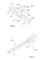
- Fig. 2 shows a medical device 100 for removal of an intact tissue specimen.
- the device 100 includes an elongated shaft/carrier 14 on which sensors S 1 -S 8 of a tissue characterization probe 12 are mounted in spaced-apart locations, and a tissue cutting tool (generally, a treatment tool) 16 mounted on the carrier 14.
- a tissue cutting tool generally, a treatment tool
- the cutting tool 16 has a body portion 22 located inside the carrier 14, and an excision element 20 projectable from the body 22 through an opening 18 made in the carrier 14
- the excision element 20 is shown in its operative projecting state.
- the excision element has a cutting edge 21, and may be configured to have a cup-like shape when in the projecting state, thereby enabling collection of tissue while being cut during the rotation of the carrier 14 and thus of the excision element 20.
- the excision element 20 extends between its first and second ends 20A and 20B which are attached to respective first and second locations on the treatment tool body 22 and spaced-apart along the axis LA of the carrier 14.
- the treatment tool is configured to enable a controllable change of the dimensions of the excision element 20.
- this is implemented by making the treatment tool body 22 from two spaced members 22A and 22B, where at least one of them is slidable with respect to the other along the carrier axis LA.
- a distance between the first and second locations, and accordingly the first and second ends 20A and 20B of the excision element changes, thereby enable adjustment of the dimension of the cutting portion 21 projecting through the carrier 14.
- the excision element distal and proximal ends 20A and 20B along the carrier 14, and thus controlling the excision volume a user can perform optimal removal of a tissue specimen, for example during a breast biopsy procedure.
- the entire excision element 20 may be movable along the body 22.
- the excision volume is controlled by user by changing the location of the excision element 20 along the carrier 14 and changing a distance between the distal and proximal ends of the excision element.
- a device 200 includes a carrier 114 formed by two separate parts 114A and 114B kept together by a treatment tool 16 inside the carrier 114.
- the treatment tool 16 has a body part 22 formed by two spaced-apart members 22A and 22B, and an excision element 120 attached thereto by its distal and proximal ends 20A and 20B.
- the excision element 120 has a semi-spherical surface 124 defining a cutting edge 21.
- the surface 124 has two arc-like portions 124A and 124B movable along the axis LA such that when they move towards one another one of the portions 124A becomes received by the other portion 124B. Also, the surface 124 has two parts 124C and 124D separately movable such that portion 124C can be received by portion 124C. These movements allow for altering the excision volume when in the operative projecting state of the excision element 120 and for shifting the element 120 between its operative projecting position and its inoperative position being located inside the carrier 14. Cutting is implemented while rotating the tool body 22 with respect to the carrier 14. Also, this configuration allows for collecting the tissue specimen while being cut.
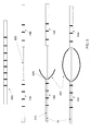
- Fig. 4 shows a medical device 300.
- a treatment tool 216 has a body shaft 22 carrying at its distal end an excision element 220.
- the latter may or may not be integral with the body shaft 22.
- the excision element has a closed-loop cutting edge 221 which is pre-bent at fabrication so as to deploy from its inoperative closed position when inside the carrier 14 into an open ring-like shape when being projected from the carrier. Attached to the cutting edge 221 is a flexible tissue collecting unit. When the excision element is pushed (by user) out of the carrier 14 through its distal end, it gradually passes through its different operative states being of a spoon-like shape of different dimensions.
- Fig. 5 shows a medical device 400.
- an elongated shaft (carrier) 14 is separable into two sections 14a and 14b, which remain connected to each other by a wire or shaft 430.
- a treatment tool 316 located inside the carrier 14 has a body shaft 22 carrying at its distal end 22A excision elements 320. The latter may or may not be integral with the body shaft 22.
- the treatment tool shaft 22 is advanced inside the shaft 14 until its distal end 22A reaches the distal end of the section 14A. Excision elements 220 are then deployed so as to excise an intact tissue portion.
- FIG. 6 shows a medical device 500.
- peripheral slots 310 are provided in the shaft/carrier 14 being interspaced between tissue characterization sensors.
- a treatment tool 416 has a body shaft 22 carrying at its distal end excision elements 420. The latter may or may not be integral with the body shaft 22.
- a number of excision elements 320 corresponds to the number of the slots 310.
- the treatment tool 416 is advanced inside the shaft 14 until its distal end is positioned at a specific slot 310 location.
- the distal end of the treatment tool shaft 22 has a tapered/angled ending portion 330. This ending portion allows for controlling an angle at which the excision elements 420 is extended from the shaft 14 into tissue.
- the excision elements 420 are pre-bent so that when extended they close back on the shaft 14, thus cutting the tissue portion adjacent to the shaft 14. Additionally, the excision elements 420 may be connected at their ends by wires, or other flexible connection. This connection can be manipulated to induce the contraction of the excision elements 420 towards shaft 14, to facilitate cutting of the tissue portion adjacent to the shaft 14.
- the device may be rotated, manually or mechanically, to assist in completer tissue treatment (e.g. cutting and removal).
Landscapes
- Health & Medical Sciences (AREA)
- Life Sciences & Earth Sciences (AREA)
- Surgery (AREA)
- Animal Behavior & Ethology (AREA)
- Biomedical Technology (AREA)
- Heart & Thoracic Surgery (AREA)
- Medical Informatics (AREA)
- Molecular Biology (AREA)
- Pathology (AREA)
- Engineering & Computer Science (AREA)
- General Health & Medical Sciences (AREA)
- Public Health (AREA)
- Veterinary Medicine (AREA)
- Surgical Instruments (AREA)
- Measuring And Recording Apparatus For Diagnosis (AREA)
- Ultra Sonic Daignosis Equipment (AREA)
Claims (15)
- System zur Verwendung bei der Gewebecharakterisierung und Behandlung, welches eine medizinische Einrichtung (10, 100) und eine damit verknüpfbare Steuereinheit umfasst, worin
Die Einrichtung (10, 100) eine Gewebecharakterisierungs-Sonde (12) mit einem Träger (14), welcher mehrere Gewebecharakterisierungs-Sensoren (S1-S8) umfasst, worin jeder Gewebecharakterisierungs-Sensor ausgestaltet und betriebsfähig ist, ein Gewebecharakterisierungs-Signal zu erzeugen, worin der Träger (14) länglich mit einer Längsachse (LA) ist und ausgestaltet ist, ein Behandlungswerkzeug (16) zu tragen;
Worin die Gewebecharakterisierungs-Sensoren (S1-S8) in einem Array entlang der Längsachse (LA) in einem beabstandeten Verhältnis mit bekannten Abständen dazwischen mindestens entlang der Längsachse (LA) des Trägers (14) angeordnet sind, so dass während des Vorschubs der Sonde (12) durch eine Gewebemasse entlang einer Durchmusterungs-Achse, welche die Längsachse (LA) ist, jeder Sensor die Gewebecharakterisierungs-Signale von seiner nachfolgenden Position entlang der Durchmusterungs-Achse erzeugt, dadurch gekennzeichnet, dass
die Steuereinheit ausgestaltet und betriebsfähig ist, die Gewebecharakterisierungs-Signale von jedem der Sensoren (S1-S8) während dieser an nachfolgenden Position entlang der Durchmusterungsachse ist, zu empfangen und zu analysieren, und die Daten, die die bekannten Abstände zwischen den jeweiligen Sensoren (S1-S8) anzeigen, zu verwenden, um eine Abmessung einer abnormalen Gewebeprobe in der Gewebemasse basierend auf den kontinuierlich empfangenen Charakterisierungs-Signalen von den nachfolgenden Positionen der Sensoren (S1-S8) in dem Array zu bestimmen. - System nach Anspruch 1, worin die Abstände zwischen den Gewebecharakterisierungs-Sensoren (S1-S8) in dem Array gleich sind oder nicht.
- System nach Anspruch 1 oder 2, worin der längliche Träger (14) ein Behandlungswerkzeug (16) trägt.
- System nach Anspruch 3, worin das Behandlungswerkzeug (16) mindestens einen Gewebebehandlungsbereich aufweist, und worin das Behandlungswerkzeug (16) ausgestaltet und betriebsfähig ist, zwischen dessen Ruhestellung, die im Wesentlichen vollständig innerhalb des Trägers (14) angeordnet ist, und dessen Betriebsstellung, bei der mindestens ein Gewebe-Behandlungsbereich aus dem Träger (14) vorsteht, selektiv versetzbar ist.
- System nach Anspruch 4, worin das Behandlungswerkzeug (16) mit einer variablen Abmessung des mindestens einen Gewebebehandlungsbereichs, der von dem Träger (14) vorsteht, ausgestaltet und betriebsfähig ist.
- System nach Anspruch 5, worin der Gewebebehandlungsbereich des Behandlungswerkzeugs (16) hinsichtlich des Trägers (14) entlang der Achse bewegbar ist.
- System nach Anspruch 4, worin das Behandlungswerkzeug (16) ausgestaltet ist, mindestens eines der Folgenden durchzuführen: Biopsie, Schneiden, Liefern einer körperlichen Behandlung, Liefern einer Behandlungs-Medikation, Diagnose.
- System nach Anspruch 4, worin der Gewebebehandlungsbereich als Gewebe-Ausschneidelement (20) ausgestaltet ist.
- System nach Anspruch 8, worin das mindestens eine Gewebe-Ausschneidelement (20) eine Gewebesammeleinheit zum Sammeln von zu entfernendem Gewebe umfasst.
- System nach Anspruch 8, worin das Behandlungswerkzeug (16) einen Körper und mindestens ein Gewebe-Ausschneidelement (20), das aus dem Körper herausgeschoben werden kann, umfasst
- System nach Anspruch 10, worin sich das Gewebe-Ausschneidelement (20) zwischen seinem ersten und zweiten Ende erstreckt, die an den jeweiligen ersten und zweiten Positionen auf dem Behandlungswerkzeug (16) -Körper angebracht und entlang einer Achse des Trägers (14) voneinander beabstandet sind.
- System nach Anspruch 11, worin sich das Behandlungswerkzeug (16) entlang mindestens einem Teil des Trägers (14) darin erstreckt, so dass mindestens die erste oder zweite Position entlang der Achse des Trägers (14) auf die andere zubewegt oder von dieser wegbewegt werden kann, wodurch die Abmessung eines Bereichs des Gewebe-Ausschneidelements (20), der von dem Träger (14) vorsteht, eingestellt wird.
- System nach Anspruch 3, worin das Behandlungswerkzeug (16) ausgestaltet ist, um die abnormale Gewebeprobe zu behandeln, worin das Behandlungswerkzeug (16) ausgestaltet und betriebsfähig ist, zwischen seiner Ruhestellung, die im Wesentlichen vollständig innerhalb des Trägers (14) angeordnet ist, und seiner Betriebsstellung, bei der mindestens ein Gewebe-Behandlungsbereich aus dem Träger (14) vorsteht, selektiv versetzbar zu sein.
- System nach Anspruch 3, worin das Behandlungswerkzeug (16) ausgestaltet ist, die abnormale Gewebeprobe zu entfernen, worin das Behandlungswerkzeug (16) ausgestaltet und betriebsfähig ist, zwischen seiner Ruhestellung, die im Wesentlichen vollständig innerhalb des Trägers (14) angeordnet ist, und seiner Betriebsstellung, bei der mindestens ein Teil von mindestens einem Gewebe-Behandlungsbereich aus dem Träger (14) vorsteht, selektiv versetzbar zu sein.
- System nach Anspruch 3, worin das Behandlungswerkzeug (16) ausgestaltet ist, die abnormale Gewebeprobe zu entfernen, worin das Behandlungswerkzeug (16) einen Körper aufweist, der sich mindestens in einen Teil des Trägers (14) erstreckt, und mindestens ein Ausschneidelement (20), worin das Ausschneidelement (20) selektiv aus dem Körper auf den Ausenbereich des Trägers (14) herausgestreckt werden kann worin sein vorstehender Bereich variable Abmessungen aufweist.
Priority Applications (1)
| Application Number | Priority Date | Filing Date | Title |
|---|---|---|---|
| EP12168882A EP2535006A3 (de) | 2007-07-16 | 2008-07-13 | Medizinische Vorrichtung zur Gewebe-Kennzeichnung und -Behandlung |
Applications Claiming Priority (2)
| Application Number | Priority Date | Filing Date | Title |
|---|---|---|---|
| US95008107P | 2007-07-16 | 2007-07-16 | |
| PCT/IL2008/000965 WO2009010960A2 (en) | 2007-07-16 | 2008-07-13 | Medical device and method for use in tissue characterization and treatment |
Related Child Applications (1)
| Application Number | Title | Priority Date | Filing Date |
|---|---|---|---|
| EP12168882A Division-Into EP2535006A3 (de) | 2007-07-16 | 2008-07-13 | Medizinische Vorrichtung zur Gewebe-Kennzeichnung und -Behandlung |
Publications (2)
| Publication Number | Publication Date |
|---|---|
| EP2178443A2 EP2178443A2 (de) | 2010-04-28 |
| EP2178443B1 true EP2178443B1 (de) | 2015-07-08 |
Family
ID=39870512
Family Applications (2)
| Application Number | Title | Priority Date | Filing Date |
|---|---|---|---|
| EP12168882A Withdrawn EP2535006A3 (de) | 2007-07-16 | 2008-07-13 | Medizinische Vorrichtung zur Gewebe-Kennzeichnung und -Behandlung |
| EP08776603.6A Not-in-force EP2178443B1 (de) | 2007-07-16 | 2008-07-13 | Medizinische Vorrichtung zur Verwendung in der Gewebecharakterisierung und Behandlung |
Family Applications Before (1)
| Application Number | Title | Priority Date | Filing Date |
|---|---|---|---|
| EP12168882A Withdrawn EP2535006A3 (de) | 2007-07-16 | 2008-07-13 | Medizinische Vorrichtung zur Gewebe-Kennzeichnung und -Behandlung |
Country Status (4)
| Country | Link |
|---|---|
| US (1) | US9301734B2 (de) |
| EP (2) | EP2535006A3 (de) |
| ES (1) | ES2547018T3 (de) |
| WO (1) | WO2009010960A2 (de) |
Families Citing this family (13)
| Publication number | Priority date | Publication date | Assignee | Title |
|---|---|---|---|---|
| US9757098B2 (en) | 2007-07-16 | 2017-09-12 | Dune Medical Devices Ltd. | Medical device and method for use in tissue characterization and treatment |
| US9999353B2 (en) | 2007-07-16 | 2018-06-19 | Dune Medical Devices Ltd. | Medical device and method for use in tissue characterization and treatment |
| US9901362B2 (en) | 2007-07-16 | 2018-02-27 | Dune Medical Devices Ltd. | Medical device and method for use in tissue characterization and treatment |
| EP2535006A3 (de) | 2007-07-16 | 2013-02-27 | Dune Medical Devices Ltd. | Medizinische Vorrichtung zur Gewebe-Kennzeichnung und -Behandlung |
| CN102573622B (zh) | 2009-08-03 | 2016-01-27 | 沙丘医疗设备有限公司 | 用于对受试者进行测量的电磁传感器 |
| WO2011016034A2 (en) | 2009-08-03 | 2011-02-10 | Dune Medical Devices Ltd. | Surgical tool |
| JP6470173B2 (ja) * | 2012-07-12 | 2019-02-13 | デューン メディカル デヴァイシズ リミテッドDune Medical Devices Ltd. | 組織性状診断及び治療で用いる医療装置 |
| WO2016090122A1 (en) | 2014-12-03 | 2016-06-09 | PAVmed Inc. | Systems and methods for percutaneous division of fibrous structures |
| EP3292822A3 (de) | 2016-08-15 | 2018-05-23 | Dune Medical Devices Ltd. | Biopsievorrichtung |
| US20180049728A1 (en) * | 2016-08-22 | 2018-02-22 | The Charles Stark Draper Laboratory, Inc. | Instrumented biopsy probe |
| US11071601B2 (en) * | 2019-11-11 | 2021-07-27 | Procept Biorobotics Corporation | Surgical probes for tissue resection with robotic arms |
| US12156693B2 (en) | 2020-05-27 | 2024-12-03 | PAVmed Inc. | Systems and methods for minimally-invasive division of fibrous structures |
| US20230404552A1 (en) * | 2022-05-19 | 2023-12-21 | Dilon Medical Technologies Ltd. | Biopsy devices and methods |
Citations (2)
| Publication number | Priority date | Publication date | Assignee | Title |
|---|---|---|---|---|
| WO2001074252A2 (en) * | 2000-03-31 | 2001-10-11 | Rita Medical Systems Inc. | Tissue biopsy and treatment apparatus and method |
| WO2007083310A2 (en) * | 2006-01-18 | 2007-07-26 | Dune Medical Devices Ltd. | System and method for analysis and treatment of a body tissue |
Family Cites Families (27)
| Publication number | Priority date | Publication date | Assignee | Title |
|---|---|---|---|---|
| US6120437A (en) * | 1988-07-22 | 2000-09-19 | Inbae Yoon | Methods for creating spaces at obstructed sites endoscopically and methods therefor |
| US5318023A (en) * | 1991-04-03 | 1994-06-07 | Cedars-Sinai Medical Center | Apparatus and method of use for a photosensitizer enhanced fluorescence based biopsy needle |
| US6006755A (en) * | 1994-06-24 | 1999-12-28 | Edwards; Stuart D. | Method to detect and treat aberrant myoelectric activity |
| DE69733815T2 (de) * | 1996-02-15 | 2006-06-08 | Biosense Webster, Inc., Diamond Bar | Sonde zur exkavation |
| US5827313A (en) | 1996-09-27 | 1998-10-27 | Boston Scientific Corporation | Device for controlled longitudinal movement of an operative element within a catheter sheath and method |
| US5846513B1 (en) * | 1997-07-08 | 2000-11-28 | Carewise Medical Products Corp | Tumor localization and removal system using penetratable detection probe and removal instrument |
| US6626903B2 (en) | 1997-07-24 | 2003-09-30 | Rex Medical, L.P. | Surgical biopsy device |
| US6602204B2 (en) * | 1998-02-10 | 2003-08-05 | Artemis Medical, Inc | Intraoperative tissue treatment methods |
| US6331166B1 (en) | 1998-03-03 | 2001-12-18 | Senorx, Inc. | Breast biopsy system and method |
| US6440147B1 (en) * | 1998-09-03 | 2002-08-27 | Rubicor Medical, Inc. | Excisional biopsy devices and methods |
| US6626899B2 (en) | 1999-06-25 | 2003-09-30 | Nidus Medical, Llc | Apparatus and methods for treating tissue |
| US6346649B1 (en) * | 1999-12-28 | 2002-02-12 | Basf Aktiengesellschaft | Process for the recovery and recycle of D-tartaric acid |
| US7201722B2 (en) | 2000-04-18 | 2007-04-10 | Allegiance Corporation | Bone biopsy instrument having improved sample retention |
| US6419635B1 (en) * | 2000-08-11 | 2002-07-16 | General Electric Compsany | In situ tumor temperature profile measuring probe and method |
| US6419640B1 (en) * | 2000-10-03 | 2002-07-16 | Thomas V. Taylor | Multiple-specimen, endoscopic biopsy forceps |
| US6832111B2 (en) * | 2001-07-06 | 2004-12-14 | Hosheng Tu | Device for tumor diagnosis and methods thereof |
| US6585734B2 (en) * | 2001-09-17 | 2003-07-01 | Melvin Levinson | Tissue cutting and retrieval device and method |
| US7505811B2 (en) | 2001-11-19 | 2009-03-17 | Dune Medical Devices Ltd. | Method and apparatus for examining tissue for predefined target cells, particularly cancerous cells, and a probe useful in such method and apparatus |
| US6813515B2 (en) | 2002-01-04 | 2004-11-02 | Dune Medical Devices Ltd. | Method and system for examining tissue according to the dielectric properties thereof |
| US8116845B2 (en) | 2005-08-04 | 2012-02-14 | Dune Medical Devices Ltd. | Tissue-characterization probe with effective sensor-to-tissue contact |
| US7122011B2 (en) | 2003-06-18 | 2006-10-17 | Rubicor Medical, Inc. | Methods and devices for cutting and collecting soft tissue |
| US20050203419A1 (en) | 2004-02-24 | 2005-09-15 | Nirmala Ramanujam | Side-firing probe for performing optical spectroscopy during core needle biopsy |
| EP1890596B1 (de) | 2005-03-29 | 2013-10-02 | Dune Medical Devices Ltd. | Elektromagnetische sensoren zur gewebecharakterisierung |
| EP2535006A3 (de) | 2007-07-16 | 2013-02-27 | Dune Medical Devices Ltd. | Medizinische Vorrichtung zur Gewebe-Kennzeichnung und -Behandlung |
| US8413582B1 (en) | 2009-03-24 | 2013-04-09 | Microfabrica Inc. | Linear escapements, methods for making, and use |
| CN102573622B (zh) | 2009-08-03 | 2016-01-27 | 沙丘医疗设备有限公司 | 用于对受试者进行测量的电磁传感器 |
| RU2012125263A (ru) | 2009-11-17 | 2013-12-27 | Гарвард Байосайенс, Инк. | Биореакторы, системы и способы для производства и/или исследования органов |
-
2008
- 2008-07-13 EP EP12168882A patent/EP2535006A3/de not_active Withdrawn
- 2008-07-13 US US12/663,923 patent/US9301734B2/en active Active
- 2008-07-13 EP EP08776603.6A patent/EP2178443B1/de not_active Not-in-force
- 2008-07-13 WO PCT/IL2008/000965 patent/WO2009010960A2/en not_active Ceased
- 2008-07-13 ES ES08776603.6T patent/ES2547018T3/es active Active
Patent Citations (2)
| Publication number | Priority date | Publication date | Assignee | Title |
|---|---|---|---|---|
| WO2001074252A2 (en) * | 2000-03-31 | 2001-10-11 | Rita Medical Systems Inc. | Tissue biopsy and treatment apparatus and method |
| WO2007083310A2 (en) * | 2006-01-18 | 2007-07-26 | Dune Medical Devices Ltd. | System and method for analysis and treatment of a body tissue |
Also Published As
| Publication number | Publication date |
|---|---|
| WO2009010960A2 (en) | 2009-01-22 |
| US9301734B2 (en) | 2016-04-05 |
| WO2009010960A3 (en) | 2009-05-07 |
| EP2535006A2 (de) | 2012-12-19 |
| EP2535006A3 (de) | 2013-02-27 |
| US20100168611A1 (en) | 2010-07-01 |
| EP2178443A2 (de) | 2010-04-28 |
| ES2547018T3 (es) | 2015-09-30 |
Similar Documents
| Publication | Publication Date | Title |
|---|---|---|
| US9301734B2 (en) | Medical device and method for use in tissue characterization and treatment | |
| US20240268801A1 (en) | Soft tissue coring biospy devices and methods | |
| US10231750B2 (en) | Excisional device distal working end actuation mechanism and method | |
| KR101541210B1 (ko) | 실시간 병리 | |
| EP2152153B1 (de) | Bewertungswerkzeug für saubere ränder | |
| JP7073460B2 (ja) | 超音波イメージングのための医療装置 | |
| US20020111564A1 (en) | Tissue acquisition system and method of use | |
| JP2005501646A (ja) | 組織を切断および除去するための装置および方法 | |
| US9999353B2 (en) | Medical device and method for use in tissue characterization and treatment | |
| US9901362B2 (en) | Medical device and method for use in tissue characterization and treatment | |
| US9757098B2 (en) | Medical device and method for use in tissue characterization and treatment | |
| EP2872046B1 (de) | Medizinische vorrichtung zur verwendung in einer gewebekennzeichnung und -behandlung | |
| JP2019527112A (ja) | 医用撮像システム | |
| KR102494673B1 (ko) | 유방 검체 절단 기구 및 유방 검체 절단 방법 | |
| US20250235232A1 (en) | Cannula with internal visualization and tissue targeting resection device |
Legal Events
| Date | Code | Title | Description |
|---|---|---|---|
| PUAI | Public reference made under article 153(3) epc to a published international application that has entered the european phase |
Free format text: ORIGINAL CODE: 0009012 |
|
| 17P | Request for examination filed |
Effective date: 20100209 |
|
| AK | Designated contracting states |
Kind code of ref document: A2 Designated state(s): AT BE BG CH CY CZ DE DK EE ES FI FR GB GR HR HU IE IS IT LI LT LU LV MC MT NL NO PL PT RO SE SI SK TR |
|
| AX | Request for extension of the european patent |
Extension state: AL BA MK RS |
|
| 17Q | First examination report despatched |
Effective date: 20100525 |
|
| DAX | Request for extension of the european patent (deleted) | ||
| GRAP | Despatch of communication of intention to grant a patent |
Free format text: ORIGINAL CODE: EPIDOSNIGR1 |
|
| INTG | Intention to grant announced |
Effective date: 20150324 |
|
| GRAS | Grant fee paid |
Free format text: ORIGINAL CODE: EPIDOSNIGR3 |
|
| GRAA | (expected) grant |
Free format text: ORIGINAL CODE: 0009210 |
|
| AK | Designated contracting states |
Kind code of ref document: B1 Designated state(s): AT BE BG CH CY CZ DE DK EE ES FI FR GB GR HR HU IE IS IT LI LT LU LV MC MT NL NO PL PT RO SE SI SK TR |
|
| REG | Reference to a national code |
Ref country code: GB Ref legal event code: FG4D |
|
| REG | Reference to a national code |
Ref country code: AT Ref legal event code: REF Ref document number: 734745 Country of ref document: AT Kind code of ref document: T Effective date: 20150715 Ref country code: CH Ref legal event code: EP |
|
| REG | Reference to a national code |
Ref country code: IE Ref legal event code: FG4D |
|
| REG | Reference to a national code |
Ref country code: DE Ref legal event code: R096 Ref document number: 602008038940 Country of ref document: DE |
|
| REG | Reference to a national code |
Ref country code: ES Ref legal event code: FG2A Ref document number: 2547018 Country of ref document: ES Kind code of ref document: T3 Effective date: 20150930 |
|
| REG | Reference to a national code |
Ref country code: NL Ref legal event code: FP |
|
| REG | Reference to a national code |
Ref country code: AT Ref legal event code: MK05 Ref document number: 734745 Country of ref document: AT Kind code of ref document: T Effective date: 20150708 |
|
| REG | Reference to a national code |
Ref country code: LT Ref legal event code: MG4D |
|
| PG25 | Lapsed in a contracting state [announced via postgrant information from national office to epo] |
Ref country code: LT Free format text: LAPSE BECAUSE OF FAILURE TO SUBMIT A TRANSLATION OF THE DESCRIPTION OR TO PAY THE FEE WITHIN THE PRESCRIBED TIME-LIMIT Effective date: 20150708 Ref country code: GR Free format text: LAPSE BECAUSE OF FAILURE TO SUBMIT A TRANSLATION OF THE DESCRIPTION OR TO PAY THE FEE WITHIN THE PRESCRIBED TIME-LIMIT Effective date: 20151009 Ref country code: LV Free format text: LAPSE BECAUSE OF FAILURE TO SUBMIT A TRANSLATION OF THE DESCRIPTION OR TO PAY THE FEE WITHIN THE PRESCRIBED TIME-LIMIT Effective date: 20150708 Ref country code: NO Free format text: LAPSE BECAUSE OF FAILURE TO SUBMIT A TRANSLATION OF THE DESCRIPTION OR TO PAY THE FEE WITHIN THE PRESCRIBED TIME-LIMIT Effective date: 20151008 Ref country code: FI Free format text: LAPSE BECAUSE OF FAILURE TO SUBMIT A TRANSLATION OF THE DESCRIPTION OR TO PAY THE FEE WITHIN THE PRESCRIBED TIME-LIMIT Effective date: 20150708 |
|
| PG25 | Lapsed in a contracting state [announced via postgrant information from national office to epo] |
Ref country code: PL Free format text: LAPSE BECAUSE OF FAILURE TO SUBMIT A TRANSLATION OF THE DESCRIPTION OR TO PAY THE FEE WITHIN THE PRESCRIBED TIME-LIMIT Effective date: 20150708 Ref country code: SE Free format text: LAPSE BECAUSE OF FAILURE TO SUBMIT A TRANSLATION OF THE DESCRIPTION OR TO PAY THE FEE WITHIN THE PRESCRIBED TIME-LIMIT Effective date: 20150708 Ref country code: AT Free format text: LAPSE BECAUSE OF FAILURE TO SUBMIT A TRANSLATION OF THE DESCRIPTION OR TO PAY THE FEE WITHIN THE PRESCRIBED TIME-LIMIT Effective date: 20150708 Ref country code: IS Free format text: LAPSE BECAUSE OF FAILURE TO SUBMIT A TRANSLATION OF THE DESCRIPTION OR TO PAY THE FEE WITHIN THE PRESCRIBED TIME-LIMIT Effective date: 20151108 Ref country code: HR Free format text: LAPSE BECAUSE OF FAILURE TO SUBMIT A TRANSLATION OF THE DESCRIPTION OR TO PAY THE FEE WITHIN THE PRESCRIBED TIME-LIMIT Effective date: 20150708 Ref country code: PT Free format text: LAPSE BECAUSE OF FAILURE TO SUBMIT A TRANSLATION OF THE DESCRIPTION OR TO PAY THE FEE WITHIN THE PRESCRIBED TIME-LIMIT Effective date: 20151109 |
|
| REG | Reference to a national code |
Ref country code: CH Ref legal event code: PL |
|
| REG | Reference to a national code |
Ref country code: DE Ref legal event code: R097 Ref document number: 602008038940 Country of ref document: DE |
|
| REG | Reference to a national code |
Ref country code: IE Ref legal event code: MM4A |
|
| PG25 | Lapsed in a contracting state [announced via postgrant information from national office to epo] |
Ref country code: CZ Free format text: LAPSE BECAUSE OF FAILURE TO SUBMIT A TRANSLATION OF THE DESCRIPTION OR TO PAY THE FEE WITHIN THE PRESCRIBED TIME-LIMIT Effective date: 20150708 Ref country code: EE Free format text: LAPSE BECAUSE OF FAILURE TO SUBMIT A TRANSLATION OF THE DESCRIPTION OR TO PAY THE FEE WITHIN THE PRESCRIBED TIME-LIMIT Effective date: 20150708 Ref country code: LI Free format text: LAPSE BECAUSE OF NON-PAYMENT OF DUE FEES Effective date: 20150731 Ref country code: CH Free format text: LAPSE BECAUSE OF NON-PAYMENT OF DUE FEES Effective date: 20150731 Ref country code: DK Free format text: LAPSE BECAUSE OF FAILURE TO SUBMIT A TRANSLATION OF THE DESCRIPTION OR TO PAY THE FEE WITHIN THE PRESCRIBED TIME-LIMIT Effective date: 20150708 Ref country code: SK Free format text: LAPSE BECAUSE OF FAILURE TO SUBMIT A TRANSLATION OF THE DESCRIPTION OR TO PAY THE FEE WITHIN THE PRESCRIBED TIME-LIMIT Effective date: 20150708 Ref country code: MC Free format text: LAPSE BECAUSE OF FAILURE TO SUBMIT A TRANSLATION OF THE DESCRIPTION OR TO PAY THE FEE WITHIN THE PRESCRIBED TIME-LIMIT Effective date: 20150708 |
|
| PLBE | No opposition filed within time limit |
Free format text: ORIGINAL CODE: 0009261 |
|
| STAA | Information on the status of an ep patent application or granted ep patent |
Free format text: STATUS: NO OPPOSITION FILED WITHIN TIME LIMIT |
|
| PG25 | Lapsed in a contracting state [announced via postgrant information from national office to epo] |
Ref country code: RO Free format text: LAPSE BECAUSE OF FAILURE TO SUBMIT A TRANSLATION OF THE DESCRIPTION OR TO PAY THE FEE WITHIN THE PRESCRIBED TIME-LIMIT Effective date: 20150708 |
|
| 26N | No opposition filed |
Effective date: 20160411 |
|
| REG | Reference to a national code |
Ref country code: FR Ref legal event code: PLFP Year of fee payment: 9 |
|
| PG25 | Lapsed in a contracting state [announced via postgrant information from national office to epo] |
Ref country code: IE Free format text: LAPSE BECAUSE OF NON-PAYMENT OF DUE FEES Effective date: 20150713 |
|
| PG25 | Lapsed in a contracting state [announced via postgrant information from national office to epo] |
Ref country code: SI Free format text: LAPSE BECAUSE OF FAILURE TO SUBMIT A TRANSLATION OF THE DESCRIPTION OR TO PAY THE FEE WITHIN THE PRESCRIBED TIME-LIMIT Effective date: 20150708 |
|
| PG25 | Lapsed in a contracting state [announced via postgrant information from national office to epo] |
Ref country code: BE Free format text: LAPSE BECAUSE OF FAILURE TO SUBMIT A TRANSLATION OF THE DESCRIPTION OR TO PAY THE FEE WITHIN THE PRESCRIBED TIME-LIMIT Effective date: 20150708 |
|
| PG25 | Lapsed in a contracting state [announced via postgrant information from national office to epo] |
Ref country code: MT Free format text: LAPSE BECAUSE OF FAILURE TO SUBMIT A TRANSLATION OF THE DESCRIPTION OR TO PAY THE FEE WITHIN THE PRESCRIBED TIME-LIMIT Effective date: 20150708 |
|
| PG25 | Lapsed in a contracting state [announced via postgrant information from national office to epo] |
Ref country code: BG Free format text: LAPSE BECAUSE OF FAILURE TO SUBMIT A TRANSLATION OF THE DESCRIPTION OR TO PAY THE FEE WITHIN THE PRESCRIBED TIME-LIMIT Effective date: 20150708 Ref country code: HU Free format text: LAPSE BECAUSE OF FAILURE TO SUBMIT A TRANSLATION OF THE DESCRIPTION OR TO PAY THE FEE WITHIN THE PRESCRIBED TIME-LIMIT; INVALID AB INITIO Effective date: 20080713 |
|
| PG25 | Lapsed in a contracting state [announced via postgrant information from national office to epo] |
Ref country code: CY Free format text: LAPSE BECAUSE OF FAILURE TO SUBMIT A TRANSLATION OF THE DESCRIPTION OR TO PAY THE FEE WITHIN THE PRESCRIBED TIME-LIMIT Effective date: 20150708 |
|
| REG | Reference to a national code |
Ref country code: FR Ref legal event code: PLFP Year of fee payment: 10 |
|
| PG25 | Lapsed in a contracting state [announced via postgrant information from national office to epo] |
Ref country code: TR Free format text: LAPSE BECAUSE OF FAILURE TO SUBMIT A TRANSLATION OF THE DESCRIPTION OR TO PAY THE FEE WITHIN THE PRESCRIBED TIME-LIMIT Effective date: 20150708 |
|
| PG25 | Lapsed in a contracting state [announced via postgrant information from national office to epo] |
Ref country code: LU Free format text: LAPSE BECAUSE OF NON-PAYMENT OF DUE FEES Effective date: 20150713 |
|
| REG | Reference to a national code |
Ref country code: FR Ref legal event code: PLFP Year of fee payment: 11 |
|
| REG | Reference to a national code |
Ref country code: DE Ref legal event code: R082 Ref document number: 602008038940 Country of ref document: DE Representative=s name: KILBURN & STRODE LLP, NL |
|
| PGFP | Annual fee paid to national office [announced via postgrant information from national office to epo] |
Ref country code: NL Payment date: 20220726 Year of fee payment: 15 |
|
| PGFP | Annual fee paid to national office [announced via postgrant information from national office to epo] |
Ref country code: IT Payment date: 20220725 Year of fee payment: 15 Ref country code: GB Payment date: 20220719 Year of fee payment: 15 Ref country code: ES Payment date: 20220815 Year of fee payment: 15 Ref country code: DE Payment date: 20220629 Year of fee payment: 15 |
|
| PGFP | Annual fee paid to national office [announced via postgrant information from national office to epo] |
Ref country code: FR Payment date: 20220727 Year of fee payment: 15 |
|
| REG | Reference to a national code |
Ref country code: DE Ref legal event code: R119 Ref document number: 602008038940 Country of ref document: DE |
|
| REG | Reference to a national code |
Ref country code: NL Ref legal event code: MM Effective date: 20230801 |
|
| GBPC | Gb: european patent ceased through non-payment of renewal fee |
Effective date: 20230713 |
|
| PG25 | Lapsed in a contracting state [announced via postgrant information from national office to epo] |
Ref country code: NL Free format text: LAPSE BECAUSE OF NON-PAYMENT OF DUE FEES Effective date: 20230801 |
|
| PG25 | Lapsed in a contracting state [announced via postgrant information from national office to epo] |
Ref country code: NL Free format text: LAPSE BECAUSE OF NON-PAYMENT OF DUE FEES Effective date: 20230801 Ref country code: DE Free format text: LAPSE BECAUSE OF NON-PAYMENT OF DUE FEES Effective date: 20240201 Ref country code: GB Free format text: LAPSE BECAUSE OF NON-PAYMENT OF DUE FEES Effective date: 20230713 |
|
| PG25 | Lapsed in a contracting state [announced via postgrant information from national office to epo] |
Ref country code: FR Free format text: LAPSE BECAUSE OF NON-PAYMENT OF DUE FEES Effective date: 20230731 |
|
| PG25 | Lapsed in a contracting state [announced via postgrant information from national office to epo] |
Ref country code: IT Free format text: LAPSE BECAUSE OF NON-PAYMENT OF DUE FEES Effective date: 20230713 |
|
| REG | Reference to a national code |
Ref country code: ES Ref legal event code: FD2A Effective date: 20240829 |
|
| PG25 | Lapsed in a contracting state [announced via postgrant information from national office to epo] |
Ref country code: ES Free format text: LAPSE BECAUSE OF NON-PAYMENT OF DUE FEES Effective date: 20230714 |
|
| PG25 | Lapsed in a contracting state [announced via postgrant information from national office to epo] |
Ref country code: ES Free format text: LAPSE BECAUSE OF NON-PAYMENT OF DUE FEES Effective date: 20230714 |