EP2178603B1 - Notfallrettungsvorrichtung und -verfahren - Google Patents
Notfallrettungsvorrichtung und -verfahren Download PDFInfo
- Publication number
- EP2178603B1 EP2178603B1 EP08746095.2A EP08746095A EP2178603B1 EP 2178603 B1 EP2178603 B1 EP 2178603B1 EP 08746095 A EP08746095 A EP 08746095A EP 2178603 B1 EP2178603 B1 EP 2178603B1
- Authority
- EP
- European Patent Office
- Prior art keywords
- canister
- strands
- propellant
- reflective
- strand
- Prior art date
- Legal status (The legal status is an assumption and is not a legal conclusion. Google has not performed a legal analysis and makes no representation as to the accuracy of the status listed.)
- Not-in-force
Links
Images




Classifications
-
- G—PHYSICS
- G08—SIGNALLING
- G08B—SIGNALLING SYSTEMS, e.g. PERSONAL CALLING SYSTEMS; ORDER TELEGRAPHS; ALARM SYSTEMS
- G08B5/00—Visible signalling systems, e.g. visible personal calling systems or remote indication of seats occupied
- G08B5/002—Distress signalling devices, e.g. rescue balloons
-
- A—HUMAN NECESSITIES
- A63—SPORTS; GAMES; AMUSEMENTS
- A63B—APPARATUS FOR PHYSICAL TRAINING, GYMNASTICS, SWIMMING, CLIMBING, OR FENCING; BALL GAMES; TRAINING EQUIPMENT
- A63B29/00—Apparatus for mountaineering
- A63B29/02—Mountain guy-ropes or accessories, e.g. avalanche ropes; Means for indicating the location of accidentally buried, e.g. snow-buried, persons
- A63B29/021—Means for indicating the location of accidentally buried, e.g. snow-buried, persons
-
- Y—GENERAL TAGGING OF NEW TECHNOLOGICAL DEVELOPMENTS; GENERAL TAGGING OF CROSS-SECTIONAL TECHNOLOGIES SPANNING OVER SEVERAL SECTIONS OF THE IPC; TECHNICAL SUBJECTS COVERED BY FORMER USPC CROSS-REFERENCE ART COLLECTIONS [XRACs] AND DIGESTS
- Y10—TECHNICAL SUBJECTS COVERED BY FORMER USPC
- Y10S—TECHNICAL SUBJECTS COVERED BY FORMER USPC CROSS-REFERENCE ART COLLECTIONS [XRACs] AND DIGESTS
- Y10S116/00—Signals and indicators
- Y10S116/44—Portable personal alarms
Definitions
- the present invention relates to methods and devices for locating persons in order that they may be rescued, and more particularly, to a device and method including an integrated emergency rescue line and reflective locator that serve to visually locate the area of a person to be rescued.
- the rescue line feature allows a rescuer to locate the exact location of the victim.
- This type of system has some advantages; however, because of the non-directional signal that is transmitted by the victim's unit, it is still necessary for the rescuers to first generally locate the location of the increased signal strength, and then begin a wide digging pattern in order to find the victim. The time it takes to dig in a wide area prevents timely location and extraction of the victim.
- One apparatus for locating avalanche victims making use of a radio transceiver system includes the invention disclosed in U.S. Pat. No. 6,484,021 .
- the traditional non-directional signal is improved by the use of directional antennas that provide a rescuer with a three-dimensional vector analysis capability thereby providing a better means for locating the location of the transmitting unit.
- Another type of avalanche rescue or locating device includes the invention disclosed in U.S. Pat. No. 6,270,386 .
- an avalanche life jacket having an airbag inflatable via a gas release system is provided. Upon actuation, the life jacket quickly inflates to surround at least the back and sides of the user's head to thereby provide physical protection around the user's head, and thereby creating at least some air space to help prevent suffocation of the user from being buried in the snow.
- Yet another type of avalanche rescue system includes an avalanche rescue marker system disclosed in U.S. Pat. No. 4,114,561 .
- This reference discloses the use of an inflatable marker or balloon secured to the user which is quickly inflated by a trigger assembly. When activated, the balloon inflates and rises into the air, thereby marking the location of the avalanche victim.
- EP1795235 A1 discloses a device for simultaneously ejecting reflective strands in a compact battery from a protecting pocket for searching a person buried under an avalanche.
- an emergency rescue device and method wherein the person to be rescued can be easily located by visual means. It is yet another object of the present invention to provide an emergency rescue device and method wherein the exact physical location of the victim may be quickly identified by the use of a rescue line that is attached to the victim. It is another object of the present invention to provide a rescue device and method wherein the device may be activated either automatically or manually.
- the invention comprises an emergency rescue device having a canister that houses a plurality of reflective strands or ribbons.
- a strap is used to secure the rescue device to the user.
- the strands are ejected away from the user in a multi-directional pattern.
- the strands are preferably made of a highly reflective material, such as Mylar ® , and the strands are preferably of a length such that at least some of the strands will be visible in the event the user is an avalanche victim buried in the snow.
- the strands could be approximately between 20 and 40 feet long and when the device is activated, the strands are deployed in multiple directions around the user.
- a combustible propellant or an explosive charge may be used thereby providing adequate motive force to deploy the strands and spread the strands in a multi-directional pattern away from the user.
- a percussion cap can be used to trigger the igniting of the propellant or explosive charge.
- the strands may be deployed by pressurized gas emitted from a gas cylinder that holds a quantity of compressed gas.
- the canister may include a plurality of coiled springs, and removing a lid of the canister allows the springs to expand and eject the strands in the multi-directional pattern away from the user.
- the user may manually deploy the strands by holding distal ends of the group of strands and throwing the strands away from the user's body.
- the distal ends of the strands may be weighted, such as by attached ball bearings. The user may selectively deploy one or all of the strands by throwing the strands away from the user's body.
- the reflective strands provide an immediate visual indication of the general area in which the victim can be found. Once a rescuer finds one of the strands, the rescuer may tug on the strand(s) that will directly point the rescuer to the direction in which the victim is found.
- the reflective strands create a reflective pattern that may be easily seen from aircraft, as well as rescuers on the ground.
- Figures 1 and 2 illustrate an emergency rescue device 10 in accordance with a first embodiment of the present invention.
- the rescue device 10 may be secured to the user, such as by strap 12 and adjustable buckle 14.
- a pair of rivets 16 secure canister 20 to the strap 12.
- the rescue device may be worn by the rescuer on the upper arm, or may be secured to the user's equipment, such as a backpack worn by the user.
- the canister 20 houses a plurality of reflective strands or ribbons 30 as shown in the cross-section in Fig. 2 .
- the strands 30 each have a proximal end 29 that is secured to a base material 28 within the canister.
- the base material can be, for example, a resin or glue that secures the proximal ends of the strands 30 to the bottom surface of the canister.
- a propellant 26 is housed in the canister and provides the motive force for ejecting the strands away from the canister.
- propellant as generically referred to herein is intended to cover a combustible propellant, explosive charge, compressed gas, or other means to create an over-pressure environment inside the canister thereby forcibly removing the lid 22 and ejecting the reflective strands.
- An activation element such as a percussion cap 24, is provided to activate the propellant/explosive charge.
- the lid 22 as shown in Fig. 3 is blown away from the canister and the strands 30 are deployed in a multi-directional pattern away from the canister.
- One particularly advantageous material that may be used for the strands 30 of the present invention includes nylon ribbon that is coated with a Mylar ® reflective film sheeting.
- Mylar (R) is a brand name for biaxially oriented polyethylene terephthalate (BoPET), a stretched polyester film.
- the strands may be made purely of Mylar ® material.
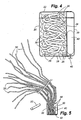
- Fig. 4 illustrates another embodiment of the present invention in which the force provided to deploy the strands is a gas cylinder 40.
- the gas cylinder 40 is disposed within the canister 20, and an activation button or plunger 42 is used to puncture a seal in the cylinder.
- a protective cover (not shown) may be placed over the plunger 42 to prevent inadvertent activation when the device is not in use.
- a thin rupturable wall 44 may be provided in the canister to separate the cylinder from the plurality of strands 30. Upon activation of the cylinder, the wall 44 ruptures thereby enabling the over-pressure gas to fill the canister. Alternatively, it is also contemplated that the actual cylinder 40 could rupture, thereby providing more of an explosive reaction within the canister to cause removal of the lid and deployment of the strands. As shown in Fig. 5 , the strands 30 deploy in the multi-directional pattern away from the canister.
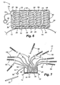
- Figs. 6 and 7 illustrate yet another embodiment of the present invention.
- a plurality of strands 30 and a plurality of deployment springs 56 are housed in the container.
- Each of the strands 30 have their proximal ends 29 secured to the base material 28.
- the strands have their opposite ends secured to the springs 56.
- a lid lock 54 is provided to keep the lid 22 attached to the canister.
- a user activates the device by pulling on the pull ring 50, which in turn causes the rip cord 52 to release the lid lock 54.
- the lid 22 separates from the canister 20 and the springs 56 that are compressed with the canister expand, thereby ejecting the strands 30 from the canister in the multi-directional pattern away from the user.
- Fig. 8 illustrates use of the rescue device wherein a skier S has deployed the device in response to an impending avalanche. As shown, the strands 30 have been ejected away from the skier in a multi-directional pattern.
- Fig. 9 illustrates the unfortunate situation in which the skier S has been buried by the avalanche and rescuers R are on scene in an attempt to rescue the victim. As shown, a few of the strands 30 are visible on the upper surface of the avalanche area A. In order to locate the victim, a rescuer R simply grasps one of the exposed strands; and then follows the strand to the exact location of the victim. As necessary, the rescuer digs the victim from the snow that covers the victim.
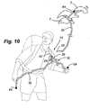
- Fig. 10 illustrates yet another preferred embodiment of the present invention.
- a user may manually disperse the strands 30 by throwing the strands in a desired pattern.
- Each of the strands has a weight 64 secured to the distal ends of the strands.
- the proximal ends of the strands may be secured to a base 62, and the base 62 may be secured to the user's clothing or equipment.
- the base 62 is secured to a chest strap of the user.
- the user may choose to throw all, or only some of the weights 64 in order to deploy the strands away from the user.
- the user could selectively throw each one of the strands in a selective pattern about the user. For example, the user could attempt to throw the weighted strands so that some of the strands loop over an adjacent tree T or bush, thereby providing an exposed reflective strand that may be more easily seen by search aircraft.
- the user then may separate the proximal end 29 from the base 62.
- a material that can be used as the weight 64 includes appropriately sized ball bearings that can be easily grasped and thrown by the user.
- Fig. 11 illustrates another preferred embodiment of the present invention.
- a pair of rescue devices 80 may be worn by the user by use of an armband 70.
- the armband includes a strap 72 and hook and pile material 74 at the ends of the strap enabling the user to adjust and secure the strap, such as to the user's arm.
- Mounting sleeves 76 are incorporated on the exposed exterior side of the armband 72 in order to receive and hold the rescue devices 80.
- the rescue devices 80 in this embodiment each include a canister 82 that houses a removable base 86.
- a plurality of retaining wires 88 are secured to the base 86, and include hooked ends 90.
- a plurality of reflective strands 92 each have proximal ends secured to the hooked ends 90.
- the reflective strands 92 are tightly packed together and are secured between the lid 84 and the hooked ends 90.
- End 96 of the rescue device 80 may be threaded and a central opening 97 receives an explosive cartridge 100.
- the explosive cartridge 100 also extends through opening 98 in the removable base 86.
- An activation element 104 is used to activate the explosive cartridge 100.
- the element 104 includes an end cap 106 that is threaded over ends 96.
- An opening 108 in the end cap 106 aligns with an activation cap 102 on the explosive cartridge 100.
- An activation arm 110 is secured to the end cap 106.
- a hammer 114 is positioned so that it may contact the cap 102 when the user pulls the lanyard 112 which is attached to the free end of the activation arm 110.
- a sharp tug or pull is made on the lanyard 112 causing the hammer 114 to strike the cap 102.
- the cap ignites the explosive material in the cartridge.
- the reflective strands 92 are ejected away from the user in the multi-directional pattern.
- the distal ends of the reflective strands 92 may include weights 94 that assist in guiding and maintaining the strands in the multi-directional pattern during ejection.
- Fig. 13 illustrates a rescuer making an attempt to rescue a victim wherein one or more of the strands 30/92 have been ejected away from the user. As shown, the rescuer grasps one of the strands and then pulls the strand, thus providing the direction towards the location of the victim.
- Fig. 14 illustrates another embodiment of the present invention in the form of a tightly wound ball 120 of reflective strand material 30/92.
- the reflective strand may be dispensed from a dispensing unit 122.
- the dispensing unit 122 includes an opening allowing the free end of the material to be grasped by the user, and a cutting edge 124 placed adjacent to the opening allows the user to separate a selected length of the material to be used.
- a user has placed the reflective strand material in a desired orientation around vegetation where the user is located.
- the reflective nature of the strand material is highly effective for overhead visual observation.
- a simple, yet effective device provides visual identification of a person to be rescued, and also provides rescuers of avalanche victims a physical connection to the exact location of the victim thereby speeding rescue efforts.
Landscapes
- Health & Medical Sciences (AREA)
- Pulmonology (AREA)
- General Health & Medical Sciences (AREA)
- Physical Education & Sports Medicine (AREA)
- Physics & Mathematics (AREA)
- General Physics & Mathematics (AREA)
- Emergency Lowering Means (AREA)
Claims (13)
- Eine Notfallrettungsvorrichtung, die Folgendes beinhaltet:einen Behälter;einen Deckel, der den Behälter abdeckt;eine Vielzahl von reflektierenden Strängen mit proximalen Enden, die in dem Behälter gesichert sind;ein in dem Behälter neben den reflektierenden Strängen platziertes Treibmittel; undein Auslösungselement, das mit dem Treibmittel kommuniziert, wobei die Auslösung des Auslösungselements bewirkt, dass das Treibmittel im Inneren des Behälters eine Überdruckumgebung erzeugt, wodurch der Deckel gewaltsam entfernt wird und die distalen Enden der reflektierenden Stränge gewaltsam von dem Behälter weg ausgestoßen werden, während die proximalen Enden in dem Behälter gesichert bleiben, so dass, wenn ein Retter an einem der ausgestoßenen Stränge zieht, der Strang direkt dorthin zeigen wird, wo eine den Behälter tragende Person zu finden ist.
- Vorrichtung gemäß Anspruch 1, die ferner Folgendes umfasst:eine in dem Behälter platzierte Basis, und wobei die proximalen Enden der reflektierenden Stränge mit dem Material der Basis verbunden sind.
- Vorrichtung gemäß Anspruch 1, wobei:das Treibmittel ein flüssiger oder gasförmiger Brennstoff ist, der bei Auslösung verbrennt.
- Vorrichtung gemäß Anspruch 1, wobei:das Treibmittel eine Sprengladung ist.
- Vorrichtung gemäß Anspruch 1, wobei:das Treibmittel ein komprimiertes Gas ist, das in dem Behälter freigesetzt wird.
- Vorrichtung gemäß Anspruch 5, wobei:das komprimierte Gas bei Auslösung des Auslösungselements aus einem Zylinder in dem Behälter freigesetzt wird.
- Vorrichtung gemäß Anspruch 1, wobei:die Stränge aus Nylon oder biaxial orientierter Polyethylenterephthalatfolie gefertigt sind.
- Vorrichtung gemäß Anspruch 1, wobei:die Stränge aus einer Kombination von Nylon und einer biaxial orientierten Polyethylenterephthalatfolie gefertigt sind.
- Eine Notfallrettungsvorrichtung, die Folgendes beinhaltet:einen Behälter;einen Deckel, der den Behälter abdeckt;eine Vielzahl von reflektierenden Strängen mit proximalen Enden, die in dem Behälter gesichert sind;eine Vielzahl von komprimierten Federn, die in dem Behälter platziert und mit distalen Enden der reflektierenden Stränge verbunden sind;eine Deckelsperre, um den Deckel über dem Behälter zu sperren; undein Auslösungselement zum Entsperren der Deckelsperre, wodurch ermöglicht wird,dass sich die Federn entkomprimieren und sich selbst, zusammen mit den distalen Enden der Stränge, von dem Behälter weg ausstoßen, während die proximalen Enden in dem Behälter gesichert bleiben, so dass, wenn ein Retter an einem der ausgestoßenen Stränge zieht, der Strang auf den genauen Ort zeigen wird, an dem eine den Behälter tragende Person zu finden ist.
- Vorrichtung gemäß Anspruch 9, wobei:das Auslösungselement einen Zugring und eine mit der Deckelsperre verbundene Schnur umfasst.
- Ein Verfahren zum Bereitstellen einer visuell wahrnehmbaren Rettungsvorrichtung, die mit einem zu rettenden Benutzer verbunden ist, wobei das Verfahren die folgenden Schritte beinhaltet:Bereitstellen einer Notfallrettungsvorrichtung, die Folgendes beinhaltet:(i) einen Behälter;(ii) einen Deckel, der den Behälter abdeckt;(iii) eine Vielzahl von reflektierenden Strängen mit proximalen Enden, die an dem Behälter gesichert sind;(iv) ein in dem Behälter neben den reflektierenden Strängen platziertes Treibmittel; und(v) ein Auslösungselement, das mit dem Treibmittel kommuniziert;und Auslösen des Auslösungselements, was bewirkt, dass das Treibmittel im Inneren des Behälters eine Überdruckumgebung erzeugt, wodurch der Deckel gewaltsam entfernt wird und distale Enden der Vielzahl von reflektierenden Strängen gewaltsam in einem multidirektionalen Muster von dem Behälter weg ausgestoßen werden, während die proximalen Enden in dem Behälter gesichert bleiben, so dass, wenn ein Retter an einem der ausgestoßenen Stränge zieht, der Strang direkt dorthin zeigen wird, wo eine den Behälter tragende Person zu finden ist.
- Ein Verfahren, das die Verwendung der Vorrichtung gemäß Anspruch 1 einbezieht, das Folgendes beinhaltet:Auslösen des Auslösungselements, was bewirkt, dass das Treibmittel die distalen Enden der Vielzahl von reflektierenden Strängen in einem multidirektionalen Muster von dem Behälter weg ausstößt;Beobachten des Lawinenbereichs und Sehen mindestens eines reflektierenden Strangs,dadurch Bestimmen des allgemeinen Ortes des Lawinenopfers;Ergreifen des Strangs; undkräftiges Ziehen an dem Strang, dadurch Begradigen des Strangs entlang einem Abschnitt davon und Beobachten einer Laufrichtung des Strangs, um einen genaueren Ort des Opfers festzustellen.
- Verfahren gemäß Anspruch 12, wobei:das Treibmittel eines der Folgenden ist: (i) ein flüssiger oder gasförmiger Brennstoff,der bei Auslösung verbrennt; (ii) eine Sprengladung; und (iii) ein komprimiertes Gas,das in dem Behälter freigesetzt wird.
Applications Claiming Priority (2)
| Application Number | Priority Date | Filing Date | Title |
|---|---|---|---|
| US11/844,867 US7574973B2 (en) | 2007-08-24 | 2007-08-24 | Emergency rescue device and method |
| PCT/US2008/060614 WO2009029294A1 (en) | 2007-08-24 | 2008-04-17 | Emergency rescue device and method |
Publications (3)
| Publication Number | Publication Date |
|---|---|
| EP2178603A1 EP2178603A1 (de) | 2010-04-28 |
| EP2178603A4 EP2178603A4 (de) | 2012-03-07 |
| EP2178603B1 true EP2178603B1 (de) | 2014-07-30 |
Family
ID=40380974
Family Applications (1)
| Application Number | Title | Priority Date | Filing Date |
|---|---|---|---|
| EP08746095.2A Not-in-force EP2178603B1 (de) | 2007-08-24 | 2008-04-17 | Notfallrettungsvorrichtung und -verfahren |
Country Status (4)
| Country | Link |
|---|---|
| US (1) | US7574973B2 (de) |
| EP (1) | EP2178603B1 (de) |
| CA (1) | CA2696911C (de) |
| WO (1) | WO2009029294A1 (de) |
Families Citing this family (7)
| Publication number | Priority date | Publication date | Assignee | Title |
|---|---|---|---|---|
| WO2010098869A2 (en) * | 2009-02-27 | 2010-09-02 | Paul Stuart Auerbach | Avalanche rescue device |
| US8876574B2 (en) * | 2010-05-25 | 2014-11-04 | FiestaFive, LLC | Device for scattering confetti |
| US8832981B2 (en) * | 2011-04-18 | 2014-09-16 | Rescued In Time, Llc | Rescue locator signal |
| IL217985A (en) | 2012-02-07 | 2014-01-30 | Ventus Product Dev & Consulting Ltd | An outline for a spirit |
| RU2538912C2 (ru) * | 2012-03-05 | 2015-01-10 | Игорь Сергеевич Ковалёв | Устройство для самоспасения людей в снежной лавине |
| US10046226B2 (en) * | 2016-11-08 | 2018-08-14 | DownAlert PSD, LLC | Personal signal device to be used for water sports |
| US20240153414A1 (en) * | 2022-11-05 | 2024-05-09 | Patricia Dionne | Body-Worn Water Sports Safety Flag Device |
Family Cites Families (37)
| Publication number | Priority date | Publication date | Assignee | Title |
|---|---|---|---|---|
| US825843A (en) * | 1905-06-22 | 1906-07-10 | Daniel Potter Olmstead | Confetto-cannon. |
| GB274695A (en) * | 1926-11-17 | 1927-07-28 | Alfred Craig | Improvements in or relating to toy bombs or projectors |
| US1903082A (en) * | 1932-09-12 | 1933-03-28 | Soren S Adams | Novelty toy |
| US3229290A (en) * | 1953-03-06 | 1966-01-11 | Evan D Fisher | Releasable balloon decoys |
| US2949094A (en) * | 1958-02-20 | 1960-08-16 | Fred H Clothier | Visual aircraft finder |
| US3072372A (en) * | 1961-06-15 | 1963-01-08 | North American Aviation Inc | Deployment parachute |
| US3291096A (en) * | 1964-04-10 | 1966-12-13 | Firm Of Mccormick Barstow Shep | Expandable signal |
| GB1202315A (en) * | 1968-03-05 | 1970-08-12 | Alfred James Schermuly | Improved rescue device |
| US3744417A (en) * | 1971-02-24 | 1973-07-10 | Kaneko Co | Cracker |
| US3877096A (en) | 1974-05-02 | 1975-04-15 | George A Scesney | Inflatable personnel safety marker |
| US4114561A (en) | 1975-10-15 | 1978-09-19 | Asaro Vito F | Avalanche rescue marker system |
| US4111407A (en) | 1976-09-30 | 1978-09-05 | Litton Industrial Products, Inc. | Conical compression spring |
| US4080925A (en) * | 1977-03-14 | 1978-03-28 | General Dynamics Corporation Electronics Division | Portable surface wind indicator |
| US4270482A (en) * | 1978-01-12 | 1981-06-02 | North American Industries, Inc. | Drop marker |
| DE3237060A1 (de) | 1982-10-06 | 1984-04-12 | Aschauer-Aussenwerbung, 8000 München | Geraet zur rettung von personen in lawinen |
| US4696252A (en) * | 1986-05-30 | 1987-09-29 | Edward Grill | Signalling device |
| US4768739A (en) | 1986-12-15 | 1988-09-06 | Schnee Robert A | Emergency warning and signaling system |
| US4815677A (en) * | 1987-08-11 | 1989-03-28 | Kiwi Research & Development Corp. | Emergency locator device |
| US4850031A (en) | 1988-01-15 | 1989-07-18 | Allsop J I | Avalanche victim locating apparatus |
| US5421287A (en) * | 1993-11-17 | 1995-06-06 | Yonover; Robert N. | Visual locating device for persons lost at sea or the like |
| US5654521A (en) * | 1995-05-30 | 1997-08-05 | Green Timbers Aviation Corporation | Rocket-fired visual signalling apparatus and method employing a streamer |
| US6167249A (en) | 1997-01-22 | 2000-12-26 | John W. Hereford | Avalanche victim locating transceiving apparatus |
| DE19703656A1 (de) | 1997-01-31 | 1998-08-06 | Peter Aschauer | Lawinenrettungssystem |
| GB2325067B (en) * | 1997-06-18 | 1999-05-19 | Christopher Passmore | A personal distress location beacon |
| US6270386B1 (en) | 1997-11-05 | 2001-08-07 | Avagear Inc. | Avalanche life-preserving jacket with airbag |
| US6359568B1 (en) | 1998-11-23 | 2002-03-19 | Harry Calvin Johnson | Personal rescue device |
| US6164239A (en) * | 1999-07-14 | 2000-12-26 | Dawson; Pearlene N. | Location identification balloon system |
| US6412482B1 (en) * | 2000-01-24 | 2002-07-02 | Carl D. Rowe | Avalanche survival pack assembly |
| US6483437B1 (en) * | 2000-09-22 | 2002-11-19 | Joseph Gelchion | Compressed gas visual notification device for signaling distress |
| US6415734B1 (en) * | 2000-10-06 | 2002-07-09 | Lapuzza James | High visibility marking panel for aerial photogrammetric ground mapping |
| US6505575B1 (en) * | 2001-02-20 | 2003-01-14 | James R. Ciari | Location indicator and method |
| US6484662B1 (en) | 2001-06-08 | 2002-11-26 | Dennis C. Perucca | Reflective rescue signaling device |
| US20030094127A1 (en) * | 2001-11-21 | 2003-05-22 | Stelmach John J. | Distress signalling |
| SE528595C2 (sv) * | 2004-01-26 | 2006-12-27 | Hans Sjoeblom | Lokaliserings- signaleringsanordning |
| US20060231012A1 (en) * | 2005-04-19 | 2006-10-19 | Andrew Wamester | Portable emergency reflective signal balloon with reflective streamers |
| US7270077B2 (en) | 2005-09-12 | 2007-09-18 | Ralph Frank Beck | Avalanche survival kit |
| FR2894488B1 (fr) | 2005-12-08 | 2008-02-29 | Mathieu Tostain | Dispositif pour marquer une zone de recherche a la surface d'une avalanche. |
-
2007
- 2007-08-24 US US11/844,867 patent/US7574973B2/en not_active Expired - Fee Related
-
2008
- 2008-04-17 WO PCT/US2008/060614 patent/WO2009029294A1/en not_active Ceased
- 2008-04-17 CA CA2696911A patent/CA2696911C/en not_active Expired - Fee Related
- 2008-04-17 EP EP08746095.2A patent/EP2178603B1/de not_active Not-in-force
Also Published As
| Publication number | Publication date |
|---|---|
| WO2009029294A1 (en) | 2009-03-05 |
| US7574973B2 (en) | 2009-08-18 |
| US20090050048A1 (en) | 2009-02-26 |
| CA2696911C (en) | 2011-06-07 |
| EP2178603A4 (de) | 2012-03-07 |
| EP2178603A1 (de) | 2010-04-28 |
| CA2696911A1 (en) | 2009-03-05 |
Similar Documents
| Publication | Publication Date | Title |
|---|---|---|
| CA2696911C (en) | Emergency rescue device and method | |
| CA2818363C (en) | Rescue and retrieval apparatus and system and method of using same | |
| US7270077B2 (en) | Avalanche survival kit | |
| US7882775B2 (en) | Non-lethal restraint device with diverse deployability applications | |
| US6195039B1 (en) | Location signalling apparatus | |
| US8245617B2 (en) | Non-lethal restraint device with diverse deployability applications | |
| US7261608B2 (en) | Vest with air bag | |
| US4295438A (en) | Rescue locator signal package | |
| ES2774042T3 (es) | Paquete de rescate aéreo desplegable | |
| US8534217B2 (en) | Location signaling device | |
| US6551159B1 (en) | Automotive underwater evacuation system | |
| US20080257643A1 (en) | Rescue device and method therefor | |
| US6705572B1 (en) | Emergency low altitude parachute wherein canopy is deployed and inflated prior to use | |
| US20130247892A1 (en) | Inflatable Life Preserver And Associated Delivery System | |
| CN105905263B (zh) | 一种救生绳索装置及救生衣、水上救生设备 | |
| US20050279559A1 (en) | Airbag type safety device | |
| JPH0663167A (ja) | 気球型救命装置 | |
| CN206050019U (zh) | 一种救生绳索装置及救生衣、水上救生设备 | |
| US6651934B2 (en) | Rescue system for rescuing persons by air | |
| GB2510408A (en) | An inflatable safety gauntlet device | |
| RU2636825C1 (ru) | Устройство информирования о месте аварии транспортного средства | |
| CA2278436A1 (en) | Avalanche safety vest | |
| US5634427A (en) | Emergency signalling device | |
| EP2384265B1 (de) | Hand-sicherheitsvorrichtung | |
| CA2625325A1 (en) | Avalanche survival kit |
Legal Events
| Date | Code | Title | Description |
|---|---|---|---|
| PUAI | Public reference made under article 153(3) epc to a published international application that has entered the european phase |
Free format text: ORIGINAL CODE: 0009012 |
|
| 17P | Request for examination filed |
Effective date: 20100212 |
|
| AK | Designated contracting states |
Kind code of ref document: A1 Designated state(s): AT BE BG CH CY CZ DE DK EE ES FI FR GB GR HR HU IE IS IT LI LT LU LV MC MT NL NO PL PT RO SE SI SK TR |
|
| AX | Request for extension of the european patent |
Extension state: AL BA MK RS |
|
| DAX | Request for extension of the european patent (deleted) | ||
| A4 | Supplementary search report drawn up and despatched |
Effective date: 20120203 |
|
| RIC1 | Information provided on ipc code assigned before grant |
Ipc: G08B 5/00 20060101ALI20120130BHEP Ipc: A63B 29/02 20060101AFI20120130BHEP |
|
| 17Q | First examination report despatched |
Effective date: 20121017 |
|
| GRAP | Despatch of communication of intention to grant a patent |
Free format text: ORIGINAL CODE: EPIDOSNIGR1 |
|
| INTG | Intention to grant announced |
Effective date: 20130422 |
|
| GRAS | Grant fee paid |
Free format text: ORIGINAL CODE: EPIDOSNIGR3 |
|
| GRAP | Despatch of communication of intention to grant a patent |
Free format text: ORIGINAL CODE: EPIDOSNIGR1 |
|
| INTG | Intention to grant announced |
Effective date: 20140307 |
|
| GRAA | (expected) grant |
Free format text: ORIGINAL CODE: 0009210 |
|
| AK | Designated contracting states |
Kind code of ref document: B1 Designated state(s): AT BE BG CH CY CZ DE DK EE ES FI FR GB GR HR HU IE IS IT LI LT LU LV MC MT NL NO PL PT RO SE SI SK TR |
|
| REG | Reference to a national code |
Ref country code: GB Ref legal event code: FG4D |
|
| REG | Reference to a national code |
Ref country code: CH Ref legal event code: EP |
|
| REG | Reference to a national code |
Ref country code: AT Ref legal event code: REF Ref document number: 679665 Country of ref document: AT Kind code of ref document: T Effective date: 20140815 |
|
| REG | Reference to a national code |
Ref country code: IE Ref legal event code: FG4D |
|
| REG | Reference to a national code |
Ref country code: DE Ref legal event code: R096 Ref document number: 602008033584 Country of ref document: DE Effective date: 20140911 |
|
| REG | Reference to a national code |
Ref country code: CH Ref legal event code: NV Representative=s name: MURGITROYD AND COMPANY, CH |
|
| REG | Reference to a national code |
Ref country code: NL Ref legal event code: VDEP Effective date: 20140730 |
|
| REG | Reference to a national code |
Ref country code: LT Ref legal event code: MG4D |
|
| PG25 | Lapsed in a contracting state [announced via postgrant information from national office to epo] |
Ref country code: ES Free format text: LAPSE BECAUSE OF FAILURE TO SUBMIT A TRANSLATION OF THE DESCRIPTION OR TO PAY THE FEE WITHIN THE PRESCRIBED TIME-LIMIT Effective date: 20140730 Ref country code: BG Free format text: LAPSE BECAUSE OF FAILURE TO SUBMIT A TRANSLATION OF THE DESCRIPTION OR TO PAY THE FEE WITHIN THE PRESCRIBED TIME-LIMIT Effective date: 20141030 Ref country code: PT Free format text: LAPSE BECAUSE OF FAILURE TO SUBMIT A TRANSLATION OF THE DESCRIPTION OR TO PAY THE FEE WITHIN THE PRESCRIBED TIME-LIMIT Effective date: 20141202 Ref country code: SE Free format text: LAPSE BECAUSE OF FAILURE TO SUBMIT A TRANSLATION OF THE DESCRIPTION OR TO PAY THE FEE WITHIN THE PRESCRIBED TIME-LIMIT Effective date: 20140730 Ref country code: FI Free format text: LAPSE BECAUSE OF FAILURE TO SUBMIT A TRANSLATION OF THE DESCRIPTION OR TO PAY THE FEE WITHIN THE PRESCRIBED TIME-LIMIT Effective date: 20140730 Ref country code: GR Free format text: LAPSE BECAUSE OF FAILURE TO SUBMIT A TRANSLATION OF THE DESCRIPTION OR TO PAY THE FEE WITHIN THE PRESCRIBED TIME-LIMIT Effective date: 20141031 Ref country code: NO Free format text: LAPSE BECAUSE OF FAILURE TO SUBMIT A TRANSLATION OF THE DESCRIPTION OR TO PAY THE FEE WITHIN THE PRESCRIBED TIME-LIMIT Effective date: 20141030 Ref country code: LT Free format text: LAPSE BECAUSE OF FAILURE TO SUBMIT A TRANSLATION OF THE DESCRIPTION OR TO PAY THE FEE WITHIN THE PRESCRIBED TIME-LIMIT Effective date: 20140730 |
|
| PG25 | Lapsed in a contracting state [announced via postgrant information from national office to epo] |
Ref country code: CY Free format text: LAPSE BECAUSE OF FAILURE TO SUBMIT A TRANSLATION OF THE DESCRIPTION OR TO PAY THE FEE WITHIN THE PRESCRIBED TIME-LIMIT Effective date: 20140730 Ref country code: HR Free format text: LAPSE BECAUSE OF FAILURE TO SUBMIT A TRANSLATION OF THE DESCRIPTION OR TO PAY THE FEE WITHIN THE PRESCRIBED TIME-LIMIT Effective date: 20140730 Ref country code: IS Free format text: LAPSE BECAUSE OF FAILURE TO SUBMIT A TRANSLATION OF THE DESCRIPTION OR TO PAY THE FEE WITHIN THE PRESCRIBED TIME-LIMIT Effective date: 20141130 Ref country code: NL Free format text: LAPSE BECAUSE OF FAILURE TO SUBMIT A TRANSLATION OF THE DESCRIPTION OR TO PAY THE FEE WITHIN THE PRESCRIBED TIME-LIMIT Effective date: 20140730 Ref country code: PL Free format text: LAPSE BECAUSE OF FAILURE TO SUBMIT A TRANSLATION OF THE DESCRIPTION OR TO PAY THE FEE WITHIN THE PRESCRIBED TIME-LIMIT Effective date: 20140730 Ref country code: LV Free format text: LAPSE BECAUSE OF FAILURE TO SUBMIT A TRANSLATION OF THE DESCRIPTION OR TO PAY THE FEE WITHIN THE PRESCRIBED TIME-LIMIT Effective date: 20140730 |
|
| PG25 | Lapsed in a contracting state [announced via postgrant information from national office to epo] |
Ref country code: DK Free format text: LAPSE BECAUSE OF FAILURE TO SUBMIT A TRANSLATION OF THE DESCRIPTION OR TO PAY THE FEE WITHIN THE PRESCRIBED TIME-LIMIT Effective date: 20140730 Ref country code: EE Free format text: LAPSE BECAUSE OF FAILURE TO SUBMIT A TRANSLATION OF THE DESCRIPTION OR TO PAY THE FEE WITHIN THE PRESCRIBED TIME-LIMIT Effective date: 20140730 Ref country code: SK Free format text: LAPSE BECAUSE OF FAILURE TO SUBMIT A TRANSLATION OF THE DESCRIPTION OR TO PAY THE FEE WITHIN THE PRESCRIBED TIME-LIMIT Effective date: 20140730 Ref country code: RO Free format text: LAPSE BECAUSE OF FAILURE TO SUBMIT A TRANSLATION OF THE DESCRIPTION OR TO PAY THE FEE WITHIN THE PRESCRIBED TIME-LIMIT Effective date: 20140730 Ref country code: CZ Free format text: LAPSE BECAUSE OF FAILURE TO SUBMIT A TRANSLATION OF THE DESCRIPTION OR TO PAY THE FEE WITHIN THE PRESCRIBED TIME-LIMIT Effective date: 20140730 Ref country code: IT Free format text: LAPSE BECAUSE OF FAILURE TO SUBMIT A TRANSLATION OF THE DESCRIPTION OR TO PAY THE FEE WITHIN THE PRESCRIBED TIME-LIMIT Effective date: 20140730 |
|
| REG | Reference to a national code |
Ref country code: DE Ref legal event code: R097 Ref document number: 602008033584 Country of ref document: DE |
|
| PLBE | No opposition filed within time limit |
Free format text: ORIGINAL CODE: 0009261 |
|
| STAA | Information on the status of an ep patent application or granted ep patent |
Free format text: STATUS: NO OPPOSITION FILED WITHIN TIME LIMIT |
|
| 26N | No opposition filed |
Effective date: 20150504 |
|
| PG25 | Lapsed in a contracting state [announced via postgrant information from national office to epo] |
Ref country code: MC Free format text: LAPSE BECAUSE OF FAILURE TO SUBMIT A TRANSLATION OF THE DESCRIPTION OR TO PAY THE FEE WITHIN THE PRESCRIBED TIME-LIMIT Effective date: 20140730 Ref country code: SI Free format text: LAPSE BECAUSE OF FAILURE TO SUBMIT A TRANSLATION OF THE DESCRIPTION OR TO PAY THE FEE WITHIN THE PRESCRIBED TIME-LIMIT Effective date: 20140730 Ref country code: LU Free format text: LAPSE BECAUSE OF FAILURE TO SUBMIT A TRANSLATION OF THE DESCRIPTION OR TO PAY THE FEE WITHIN THE PRESCRIBED TIME-LIMIT Effective date: 20150417 |
|
| GBPC | Gb: european patent ceased through non-payment of renewal fee |
Effective date: 20150417 |
|
| REG | Reference to a national code |
Ref country code: IE Ref legal event code: MM4A |
|
| PG25 | Lapsed in a contracting state [announced via postgrant information from national office to epo] |
Ref country code: GB Free format text: LAPSE BECAUSE OF NON-PAYMENT OF DUE FEES Effective date: 20150417 |
|
| REG | Reference to a national code |
Ref country code: FR Ref legal event code: PLFP Year of fee payment: 9 |
|
| PG25 | Lapsed in a contracting state [announced via postgrant information from national office to epo] |
Ref country code: IE Free format text: LAPSE BECAUSE OF NON-PAYMENT OF DUE FEES Effective date: 20150417 |
|
| PG25 | Lapsed in a contracting state [announced via postgrant information from national office to epo] |
Ref country code: BE Free format text: LAPSE BECAUSE OF FAILURE TO SUBMIT A TRANSLATION OF THE DESCRIPTION OR TO PAY THE FEE WITHIN THE PRESCRIBED TIME-LIMIT Effective date: 20140730 |
|
| PG25 | Lapsed in a contracting state [announced via postgrant information from national office to epo] |
Ref country code: MT Free format text: LAPSE BECAUSE OF FAILURE TO SUBMIT A TRANSLATION OF THE DESCRIPTION OR TO PAY THE FEE WITHIN THE PRESCRIBED TIME-LIMIT Effective date: 20140730 |
|
| PG25 | Lapsed in a contracting state [announced via postgrant information from national office to epo] |
Ref country code: HU Free format text: LAPSE BECAUSE OF FAILURE TO SUBMIT A TRANSLATION OF THE DESCRIPTION OR TO PAY THE FEE WITHIN THE PRESCRIBED TIME-LIMIT; INVALID AB INITIO Effective date: 20080417 |
|
| REG | Reference to a national code |
Ref country code: FR Ref legal event code: PLFP Year of fee payment: 10 |
|
| PG25 | Lapsed in a contracting state [announced via postgrant information from national office to epo] |
Ref country code: TR Free format text: LAPSE BECAUSE OF FAILURE TO SUBMIT A TRANSLATION OF THE DESCRIPTION OR TO PAY THE FEE WITHIN THE PRESCRIBED TIME-LIMIT Effective date: 20140730 |
|
| REG | Reference to a national code |
Ref country code: FR Ref legal event code: PLFP Year of fee payment: 11 |
|
| PGFP | Annual fee paid to national office [announced via postgrant information from national office to epo] |
Ref country code: FR Payment date: 20180315 Year of fee payment: 11 |
|
| PGFP | Annual fee paid to national office [announced via postgrant information from national office to epo] |
Ref country code: CH Payment date: 20180416 Year of fee payment: 11 Ref country code: DE Payment date: 20180404 Year of fee payment: 11 |
|
| PGFP | Annual fee paid to national office [announced via postgrant information from national office to epo] |
Ref country code: AT Payment date: 20180326 Year of fee payment: 11 |
|
| REG | Reference to a national code |
Ref country code: DE Ref legal event code: R119 Ref document number: 602008033584 Country of ref document: DE |
|
| REG | Reference to a national code |
Ref country code: CH Ref legal event code: PL |
|
| REG | Reference to a national code |
Ref country code: AT Ref legal event code: MM01 Ref document number: 679665 Country of ref document: AT Kind code of ref document: T Effective date: 20190417 |
|
| PG25 | Lapsed in a contracting state [announced via postgrant information from national office to epo] |
Ref country code: LI Free format text: LAPSE BECAUSE OF NON-PAYMENT OF DUE FEES Effective date: 20190430 Ref country code: DE Free format text: LAPSE BECAUSE OF NON-PAYMENT OF DUE FEES Effective date: 20191101 Ref country code: CH Free format text: LAPSE BECAUSE OF NON-PAYMENT OF DUE FEES Effective date: 20190430 Ref country code: AT Free format text: LAPSE BECAUSE OF NON-PAYMENT OF DUE FEES Effective date: 20190417 |
|
| PG25 | Lapsed in a contracting state [announced via postgrant information from national office to epo] |
Ref country code: FR Free format text: LAPSE BECAUSE OF NON-PAYMENT OF DUE FEES Effective date: 20190430 |