EP2178704B1 - Traitement par plasma par compression - Google Patents
Traitement par plasma par compression Download PDFInfo
- Publication number
- EP2178704B1 EP2178704B1 EP08785216A EP08785216A EP2178704B1 EP 2178704 B1 EP2178704 B1 EP 2178704B1 EP 08785216 A EP08785216 A EP 08785216A EP 08785216 A EP08785216 A EP 08785216A EP 2178704 B1 EP2178704 B1 EP 2178704B1
- Authority
- EP
- European Patent Office
- Prior art keywords
- sheet
- print sheets
- surface modification
- printing press
- Prior art date
- Legal status (The legal status is an assumption and is not a legal conclusion. Google has not performed a legal analysis and makes no representation as to the accuracy of the status listed.)
- Not-in-force
Links
- 238000007639 printing Methods 0.000 title claims abstract description 95
- 238000009832 plasma treatment Methods 0.000 title claims abstract description 9
- 238000012986 modification Methods 0.000 claims abstract description 57
- 230000004048 modification Effects 0.000 claims abstract description 57
- 239000000758 substrate Substances 0.000 claims description 33
- 238000000034 method Methods 0.000 claims description 14
- 230000008569 process Effects 0.000 claims description 12
- 239000007789 gas Substances 0.000 claims description 11
- 238000012545 processing Methods 0.000 claims description 8
- 239000004033 plastic Substances 0.000 claims description 4
- 229920003023 plastic Polymers 0.000 claims description 4
- 238000000605 extraction Methods 0.000 claims description 3
- 230000009471 action Effects 0.000 claims description 2
- 238000004381 surface treatment Methods 0.000 claims description 2
- 230000004913 activation Effects 0.000 claims 1
- 238000007599 discharging Methods 0.000 abstract description 3
- 238000009736 wetting Methods 0.000 abstract description 2
- 239000000463 material Substances 0.000 description 11
- 238000000576 coating method Methods 0.000 description 8
- 239000011248 coating agent Substances 0.000 description 7
- 239000000976 ink Substances 0.000 description 6
- IJGRMHOSHXDMSA-UHFFFAOYSA-N Atomic nitrogen Chemical compound N#N IJGRMHOSHXDMSA-UHFFFAOYSA-N 0.000 description 4
- 238000004049 embossing Methods 0.000 description 4
- 239000002184 metal Substances 0.000 description 3
- 238000011144 upstream manufacturing Methods 0.000 description 3
- 239000004698 Polyethylene Substances 0.000 description 2
- 239000004743 Polypropylene Substances 0.000 description 2
- 238000003848 UV Light-Curing Methods 0.000 description 2
- 238000005520 cutting process Methods 0.000 description 2
- 238000013461 design Methods 0.000 description 2
- 238000007641 inkjet printing Methods 0.000 description 2
- 238000004519 manufacturing process Methods 0.000 description 2
- 229910052757 nitrogen Inorganic materials 0.000 description 2
- 239000003973 paint Substances 0.000 description 2
- -1 polypropylene Polymers 0.000 description 2
- 238000012546 transfer Methods 0.000 description 2
- XLYOFNOQVPJJNP-UHFFFAOYSA-N water Substances O XLYOFNOQVPJJNP-UHFFFAOYSA-N 0.000 description 2
- VGGSQFUCUMXWEO-UHFFFAOYSA-N Ethene Chemical compound C=C VGGSQFUCUMXWEO-UHFFFAOYSA-N 0.000 description 1
- TZXKOCQBRNJULO-UHFFFAOYSA-N Ferriprox Chemical compound CC1=C(O)C(=O)C=CN1C TZXKOCQBRNJULO-UHFFFAOYSA-N 0.000 description 1
- CBENFWSGALASAD-UHFFFAOYSA-N Ozone Chemical compound [O-][O+]=O CBENFWSGALASAD-UHFFFAOYSA-N 0.000 description 1
- 238000005299 abrasion Methods 0.000 description 1
- 238000007774 anilox coating Methods 0.000 description 1
- 230000000712 assembly Effects 0.000 description 1
- 238000000429 assembly Methods 0.000 description 1
- 230000015572 biosynthetic process Effects 0.000 description 1
- 239000012159 carrier gas Substances 0.000 description 1
- 239000000919 ceramic Substances 0.000 description 1
- 239000002800 charge carrier Substances 0.000 description 1
- 230000003750 conditioning effect Effects 0.000 description 1
- 238000003851 corona treatment Methods 0.000 description 1
- 230000001419 dependent effect Effects 0.000 description 1
- 238000009826 distribution Methods 0.000 description 1
- 230000009977 dual effect Effects 0.000 description 1
- 230000000694 effects Effects 0.000 description 1
- 238000003912 environmental pollution Methods 0.000 description 1
- 238000007775 flexo coating Methods 0.000 description 1
- 239000011888 foil Substances 0.000 description 1
- 238000010438 heat treatment Methods 0.000 description 1
- 229920001903 high density polyethylene Polymers 0.000 description 1
- 239000004700 high-density polyethylene Substances 0.000 description 1
- 238000009434 installation Methods 0.000 description 1
- 238000009413 insulation Methods 0.000 description 1
- 230000010354 integration Effects 0.000 description 1
- 239000004922 lacquer Substances 0.000 description 1
- 238000003475 lamination Methods 0.000 description 1
- 229920001684 low density polyethylene Polymers 0.000 description 1
- 239000004702 low-density polyethylene Substances 0.000 description 1
- 238000012423 maintenance Methods 0.000 description 1
- 238000007645 offset printing Methods 0.000 description 1
- 238000010422 painting Methods 0.000 description 1
- 239000006223 plastic coating Substances 0.000 description 1
- 239000002985 plastic film Substances 0.000 description 1
- 229920006255 plastic film Polymers 0.000 description 1
- 229920000573 polyethylene Polymers 0.000 description 1
- 229920001155 polypropylene Polymers 0.000 description 1
- 238000002203 pretreatment Methods 0.000 description 1
- 238000003672 processing method Methods 0.000 description 1
- 239000011253 protective coating Substances 0.000 description 1
- 238000004080 punching Methods 0.000 description 1
- 238000000926 separation method Methods 0.000 description 1
- 239000007787 solid Substances 0.000 description 1
- 238000003860 storage Methods 0.000 description 1
- 239000002966 varnish Substances 0.000 description 1
Images


Classifications
-
- B—PERFORMING OPERATIONS; TRANSPORTING
- B41—PRINTING; LINING MACHINES; TYPEWRITERS; STAMPS
- B41F—PRINTING MACHINES OR PRESSES
- B41F23/00—Devices for treating the surfaces of sheets, webs, or other articles in connection with printing
-
- B—PERFORMING OPERATIONS; TRANSPORTING
- B41—PRINTING; LINING MACHINES; TYPEWRITERS; STAMPS
- B41F—PRINTING MACHINES OR PRESSES
- B41F7/00—Rotary lithographic machines
- B41F7/02—Rotary lithographic machines for offset printing
- B41F7/04—Rotary lithographic machines for offset printing using printing units incorporating one forme cylinder, one transfer cylinder, and one impression cylinder, e.g. for printing on webs
- B41F7/06—Rotary lithographic machines for offset printing using printing units incorporating one forme cylinder, one transfer cylinder, and one impression cylinder, e.g. for printing on webs for printing on sheets
Definitions
- the invention relates to a sheet-fed printing machine according to the preamble of claim 1.
- Sheet-fed printing presses are used for printing sheet-like substrates, so-called printing sheet, wherein printed sheets to be printed are introduced in the area of an investor in a printing process and discharged from the printing process in the region of a boom. Between the feeder and the boom of the printing press several printing units are positioned, wherein in each printing unit a partial printing image in a special ink or a different type of coating are applied to the substrate.
- the printed sheets to be printed can be made of a variety of different materials. If printed sheets designed as plastic films or provided with a plastic coating are to be printed, then it should be noted that in particular UV-curing printing inks or water-based printing inks adhere only very poorly to the printed sheet. This is especially the case when printing sheets from difficult to print substrates or corresponding coatings such as polypropylene (PP, HDPP, LDPP) or polyethylene (PE, HDPE, LDPE) are to be printed. Thus, these plastics are materials which, due to their production, have a low surface tension and / or a low polarity. This results in printing with UV-curing inks or paints or water-based inks or paints poor wetting of such sheets and / or poor adhesion of the ink or varnish on the sheet.
- PP polypropylene
- LDPP polyethylene
- these plastics are materials which, due to their production, have a low surface tension and / or a low polarity. This results in printing with UV
- a device for treating the surfaces of printing substrates in printing machines wherein the printing material is bombarded in the region of a corona electrode with charge elements derived from discharging processes, such as electrons.
- a metallic or conductive printing cylinder on which the printing material is guided on passing the corona electrode, serves as the counterelectrode, so that an electrical discharge, which is carried out between the corona electrode and the printing cylinder serving as the counterelectrode, passes through the printing substrate through.
- a small distance of the corona electrode from the substrate in the order of 0.5 mm must be maintained, so that accessibility is severely limited.
- the DE 20 2004 008 285 U1 discloses an atmospheric pressure plasma processing tool for wide workpieces in which electrical discharges occur between electrodes and counter electrodes formed as nozzles.
- the electrodes and the counter electrodes formed as a nozzle are positioned on one side of a substrate to be treated so that the electrical discharge does not occur through the substrate.
- a plasma generated during the electric corona discharge is conducted by means of a gas, namely with the aid of compressed air, onto the surface of the substrate to be treated.
- a gas namely with the aid of compressed air
- other gases for example nitrogen, can be used to transport the plasma in the direction of the substrate.
- WO2007 / 073833 A shows a sheet-fed printing machine according to the preamble of claim 1.
- the present invention is based on the problem to provide a novel sheet-fed printing machine.
- the or each device for surface modification of printing substrates in the region of a module is integrated into the sheet-fed printing machine downstream of the feeder.
- the or each device arranged according to the invention for surface modification generates a plasma on each of its associated side of a printing substrate. Accordingly, the printing material is not positioned between the electrodes, between which an electrical charge takes place for plasma formation.
- the plasma generated by means of electrical discharges from air or other gases, such as nitrogen, for example, is conducted by means of overpressure onto the respective surface of the printing substrate.
- the feeder is designed as a bulkhead feeder and has an investment table on which the printed sheets are transported as shingled stream to a sheet system for alignment and separation of the printed sheets, wherein the means for surface modification in the area of a following on the sheet system Integrated sheet transport cylinder, in which the surface of the sheet to be modified is freely accessible.
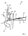
- Fig. 1 shows a schematic section of a sheet-fed press in the area of sheetfed system 10.
- the sheetfed 10 to be printed sheets are provided which are kept in a sheet feeder in the form of a stack, isolated and fed via a feed table 11 a first printing unit of the sheet-fed press.
- the sheet feeder 10 is connected to a shingled feeder, which means that in the area of the feed table 11 printed sheets 12 are transported with overlapping as a shingled stream.
- Fig. 1 schematically shows two mutually partially overlapping sheets 12 of a scale flow.
- a pre-gripper 14 detects a previously aligned sheet 12th at its front in the transport direction section, this pulls from the investment table 11 and passes it to a first cylinder 15 of Press.
- this first cylinder 15 is designed in the manner of a so-called conditioning drum.
- FIG. 1 Configuration shown can also be performed within a so-called investor-investment module.
- the upstream of a sheetfed printing machine feeder (bulkhead) with the devices for sheet supply to the sheet-fed press, which were executed as a sheet feeder 10 are combined in a single unit.
- the arrangement according to the invention can also be used.
- a device 16 for surface modification of the printing sheet 12 to be printed is integrated in the area of the sheet feeder 10 of the sheet-fed printing machine.
- the device 16 for surface modification in the sheet feeder 10 is arranged in the region in front of the so-called pre-gripper 14, where orientation of the sheet separated by a stack 12 takes place before being fed to the sheet-fed press.
- the printed sheet to be processed is exposed so that its surface is completely accessible.
- the printing sheets 12 may be subjected to a surface modification over their entire surface.
- the device 16 for surface modification of the printing substrates 12 by means of a plasma is preferably as in FIG Fig. 4 shown executed. So has the device 16 of the Fig. 4 via several electrodes, which are grouped in two consecutive rows 17 and 18, respectively. Within each of these two rows 17 and 18, four electrodes are arranged in a common housing 19 in the illustrated embodiment, with nozzles 20 of the housing 19 forming counterelectrodes for electrical discharge within the device 16. The number of rows and the associated number of electrodes per row are listed here purely by way of example.
- the device 16 is according to Fig. 1 stored on a traverse 26.
- Fig. 4 can be removed, the nozzles 20 and the electrodes, not shown, of the two rows 17 and 18 are aligned such that in the middle between two adjacent electrodes or nozzles 20 of a row an electrode or nozzle 20 of an adjacent row is positioned.
- an array of electrodes or nozzles 20 is formed by means of which the printing materials 12 can be uniformly subjected to a surface modification in the region of their surface.
- the plasma discharge required electrical discharge within the housing 19 is shown schematically, wherein the plasma formed in this case with the aid of a flowing under pressure carrier gas, eg compressed air 21, is passed through the nozzles 20 in the direction of the printing sheet 12 to be treated.
- a flowing under pressure carrier gas eg compressed air
- the nozzles 20 are preferably designed as slit nozzles and have seen in cross section parallel to the conveying plane and transverse to the direction of movement of the sheet 12 over a larger dimension than in the direction of movement of the sheet to be treated 12. This allows a particularly uniform treatment of the sheet 12 can be realized.
- FIGS. 2 and 3 it is also possible to use the device for surface modification as in FIGS. 2 and 3 shown to execute.
- a device 22 for surface modification of substrates wherein electrical discharges between each two outer electrodes 23 (see Fig. 3 ) respectively.
- a plasma 24 is formed, which is supplied with air under an overpressure as compressed air 25 to a surface of the treated Sheet 12 can be addressed.
- the compressed air 25 absorbs the charge carriers desired for the surface modification and distributes them over the surface of the printed sheet 12 to be treated.
- the electrodes 23 are open, assemblies of the printing press, which are located in the region of the device 22, to be coated in order to avoid the risk of short circuits by discharging sparks from the electrodes.
- the devices 16 and 22 for surface modification of printed sheets are arranged in the contact region of the sheet-fed printing press by means of a holder (here for example a cross-member 26). At this point they can be pivoted into a working position on the bow path.
- the devices 16 and 22 can also be designed to be pivotable away from the abutment area on the traverse 26 or with the crossbar 26.
- the units 16, 22 integrated in the contact area of the sheet-fed printing machine for the surface modification of printed sheets may finally be covered by a corresponding protection 27.
- the protection 27 can be made possible by means of a suction unit 31, the removal of the resulting warm process gases by means of a negative pressure. In order to avoid environmental pollution on site and inadmissible heating of the units 16 and 22 by the work process can be prevented.
- a device 16 for surface modification is positioned by means of which the printed sheets 12 can be treated in the region of an upper side or surface with respect to the transport plane.
- a device 16 for surface modification on both sides of the printing material If the printed sheets are to be printed on both sides, then it is also possible to respectively position a device 16 for surface modification on both sides of the printing material. So z. B. a second device for surface modification in Fig. 1 be positioned below the alignment of the sheet system 10 or below the cylinder 15 and so take over the surface modification of the substrate in the region of the second side. Likewise, the second surface modification device in the area of a sheet turning device can be integrated into the printing machine. In this case, the second device for surface modification is preferably arranged in the region after the application of the sheet, where the printed sheet 12 is everted and thus its second side is upwards. Then the device 16 for surface modification above the transport plane of the sheet path can be assigned.
- a third device for surface modification can be integrated in front of a coating unit in the sheet-fed press.
- the device for surface modification is also possible to integrate the device for surface modification exclusively in the area of a sheet turn in the sheet-fed press. This is advantageous if one-sided coated printing sheets are used, which should initially print from the uncoated side and after the sheet application of the coated side.
- the device for surface modification can be integrated exclusively in front of a coating unit in the sheet-fed press. This is advantageous if the already printed surface of the printed sheets for a final finishing treatment, e.g. by applying a glossy or protective coating to be modified.
- the devices 16, 22 for surface modification units are used, in which the electrical discharge is not carried out through the substrate.
- electrodes and counter electrodes between which each electrical discharges take place, positioned on the same side of the sheet to be treated.
- the devices 16, 22 in this case have a distance of between 5 mm and 10 mm from the respective surface of the printed sheets.
- the arrangement further features.
- the means 16 or 22 for modifying the surface of printed sheets is either provided with its own control in addition to the power supply or may be coupled to the machine control in such a way that it is adaptable in its behavior to the printing process.
- at least one point in time or duration or even the time and duration of the plasma generation at the device 16 or 22 can be adjustable.
- the settings may also be tunable with respect to the power stroke of the sheetfed press.
- the means 16 or 22 for generating the plasma used in the modification of the sheet surface can thus be limited in an efficient manner to the time during the supply of a sheet in the sheet-fed press. This prevents charges from being scattered uncontrollably into the printing machine or into the sheet feeder 10.
- the surface modification by means of the device 16, 22 done so that areas of the substrate surface are recessed both transversely and longitudinally to the feed direction. This is due to the described design of the device 16 from a series of discharge units.
- the amount of plasma generation may be adjustable to provide, in relation to the desired pressure conditions, the necessary amount of free radicals in an adaptable plasma for e.g. to achieve different adjustments of surface tensions in the modification of the surface of the printed sheets.
- the power of the discharge units is variably controlled, so that the amount of reactive plasma gas can be influenced in a targeted manner.
- the strength of the surface modification of printed sheets by the plasma on the respective substrate is adjustable. This results in differences between different substrates, as they react differently with the free radicals from the plasma. This reaction may also be variable for inherently similar materials due to variable manufacturing processes, transportation and storage conditions. Therefore, the strength of the surface modification is specifically influenced, with the main influence variable being the strength of the Plasma is. However, the duration of the plasma action, the type of gas used and the pressure of the blast air flow at the nozzles also have an effect.
- the strength of the surface modification of the printed sheets can also be adapted to the transport speed of the printed sheets.
- the strength of the plasma can be increased, so that even in a shorter time always the same amount of reactive plasma gas is available.
- the overpressure for impressing the plasma gas on the printing material can be raised.
- a device 16 for generating a plasma is assigned to a printing cylinder 30 of a sheet-guiding module and thus creates a device designed as a treatment module 29 in combination with a sheet-fed printing press.
- the treatment module 29 is arranged between the sheet feeder 10 and a first printing unit 40. Instead of the first printing unit 40 and a coating unit can be provided.
- the printed sheets 12 are performed to perform the further processing on the impression cylinder 30 of the treatment module 29 and sheet transport drums 28 by following on the treatment module 29 printing units 40, 50.
- a treatment module 29 can also be arranged in combination with a lacquer module or a differently configured unit for treatment (such as embossing, creasing, cutting) of printing substrates in the inline method.
- a treatment module 29 may also be connected in front of a sheet-fed printing press configured completely as a coating machine, in which case correspondingly downstream flexographic printing units are provided in connection with the treatment module 29.
- an embossing station may also be arranged upstream of the treatment module 29.
- the printed sheets 12 are there on the printing cylinder 30 as a single sheet.
- a full-surface treatment of the sheet surface can be made while the printed sheets 12 are held on the printing cylinder 30 and guided smoothly.
- the printing cylinder 30 itself is not provided here with a discharge generating counter electrode.
- metal-coated or metal-coated substrates can also be pretreated with the plasma system described here.
- the so-designed devices 16, 22 for surface modification can therefore be used for substrates of all currently known types of substrates.
- the surface modification by means of a discharge on substrates made of substrates with metallic surfaces is also possible.
- film, paper or board substrates with metallic lamination come into question, such as aluminum-backed substrates.
- the thermal load of the space environment compared to the arrangement in the sheet system 10 after Fig. 1 better controllable.
- the device 16 for surface modification can be moved up or down when not in use. This can be done by moving the whole unit or the electrodes.
- the treatment module 29 may be provided with a sheet guide 35 over the treatment cylinder (impression cylinder 30).
- the device described is used for inline processes with printing and / or coating in offset printing units and / or flexo coating units or modules.
- the plasma method for surface modification is preferably carried out in a first work station with integrated sheet system and upstream sheet feeder.
- FIG. 6 a plasma treatment is shown in a multifunction module 32 which serves to utilize additional processing functions.
- the sheet guide for the sheet can be touching and / or non-contact, as something air-assisted done.
- rollers, cylinders, movable hold-down rod (about in the sheet inlet in the sheet-fed press) can be used.
- the guide elements can also within the treatment module 29 or the multifunction module 32; be arranged before or after the device 16, 22.
- the device 16, 22 movably clocking with respect to the surface of the guided on the impression cylinder 30 sheet 12 may be arranged.
- the energy supply and removal, as well as a suction device 31 for gases produced in the process can be integrated both in the treatment module 29 and in the multifunction module 32.
- the modules 29, 32 are encapsulated with Vertikept 27 and provided with the suction devices 31 integrated filters, insulation devices, etc.
- the counter-cylinder 30 is preferably provided as a solid cylinder with finished surface or exchangeable surfaces such as with ceramic-coated jackets (coated sheets) or finished sheets on a support such as a skeleton drum with sheet guide plates. In case of wear by thermal abrasion, so the metal jacket can be easily replaced. To this Purpose are provided on the impression cylinder 30 integrated recording and clamping systems.
- the unit for plasma treatment according to the invention is designed as a multifunctional module 32.
- the multifunction module 32 is provided with changing systems for the use of other additional processing functions.
- devices for moving or pivoting or removing the device 16, 22 for surface modification by plasma generation are arranged for this purpose.
- a stamping cylinder 33 can be used in the multifunction module 32 or equipped with stamping tools.
- an ink-jet printing system 34 can be used in the multifunction module.
- the additional devices can be accommodated together in the multifunction module 32 and arranged for common or alternative use with respect to the effective surface on the impression cylinder 30 slidably.
- the multifunction module 32 can also be used alternatively by means of changing equipment or for dual equipping with the said or other working devices for other tasks.
- both the substrate, as well as the film to be applied can be treated by a plasma process via an associated device corresponding to the device 16, 22 for surface modification, both devices can cooperate or individual facilities can be used, the associated Supply units can be combined.
Landscapes
- Engineering & Computer Science (AREA)
- Mechanical Engineering (AREA)
- Supply, Installation And Extraction Of Printed Sheets Or Plates (AREA)
- Ink Jet (AREA)
- Plasma Technology (AREA)
- Printing Methods (AREA)
Claims (10)
- Machine d'impression de feuilles, comportant un margeur pour les feuilles à imprimer, au moins une unité d'impression pour imprimer les feuilles d'impression, un extracteur pour éjecter les feuilles d'impression imprimées et au moins un dispositif de modification de surface au moyen de charges électriques de respectivement une surface des feuilles d'impression afin de renforcer une tension surfacique des feuilles d'impression et ainsi l'aptitude à la réticulation de celles-ci avec de l'encre d'impression et/ou l'adhérence de l'encre d'impression sur les feuilles d'impression, dans laquelle
le ou les dispositifs (16, 22) de modification de surface des feuilles d'impression d'une surface librement accessible d'un cylindre (30) sont intégrés en association dans sa zone de guidage des feuilles dans la machine d'impression de feuilles,
une unité de transformation (29) installée en aval de l'installation à feuilles (10) et du système d'acheminement de feuilles (11, 14, 15) étant pourvue d'un ou plusieurs dispositifs (16) de traitement surfacique et/ou de modification de surface des feuilles d'impression, le ou chaque dispositif (16) étant intégré dans la zone du cylindre d'impression (30) dans laquelle la surface d'une feuille d'impression (12) est librement accessible,
que l'unité de transformation est réalisée sous la forme d'un module de traitement au plasma (29, 32), qu'est intégré dans la machine d'impression de feuilles en tant que dispositif (16, 22)de modification de la surface de feuilles d'impression au moins un dispositif de traitement au plasma de la surface des feuilles au niveau du module de traitement au plasma (29, 32) installé dans la machine d'impression de feuilles en aval d'au moins le système d'acheminement de feuilles (11, 14, 15) de la machine d'impression de feuilles, le plasma utilisé dans le dispositif (16, 22) de modification de la surface des feuilles d'impression étant généré par une décharge électrique entre les électrodes qui se trouvent du même côté de la surface à modifier des feuilles d'impression à traiter,
caractérisée en ce que
dans le ou chaque dispositif (16, 22), au niveau d'un cylindre d'impression (30) ou du module de traitement au plasma (29, 32), au moins un dispositif d'aspiration (31) est disposé, le ou les dispositifs (16, 22) étant habillés d'une protection qui dispose d'une simple unité d'aspiration pour aspirer les gaz de traitement chauds dégagés et
que le module de traitement au plasma (29, 32) est réalisé sous forme d'un module multifonctionnel (32) et que le module multifonctionnel (32) est pourvu à cet effet de systèmes d'interversion pour utiliser d'autres fonctions de traitements supplémentaires. - Machine d'impression de feuilles selon la revendication 1, caractérisée en ce que le plasma utilisé pour la modification de la surface des feuilles d'impression n'est généré que pendant le guidage d'une feuille d'impression (12) sur le cylindre (30) dans la machine d'impression de feuilles et/ou que le moment et/ou la durée de génération du plasma utilisé pour la modification de la surface des feuilles d'impression sont réglables.
- Machine d'impression de feuilles selon les revendications 1 à 2, caractérisée en ce que la puissance de génération du plasma utilisé pour la modification de la surface des feuilles d'impression est réglable et/ou que l'importance de la modification de la surface des feuilles d'impression par le plasma est réglable suivant le type de substrat respectivement utilisé et/ou que l'importance de la modification de la surface des feuilles d'impression est adaptable à la vitesse de transport des feuilles d'impression.
- Machine d'impression de feuilles selon les revendications 1 à 3, caractérisée en ce que, par une commande appropriée de la ou des unités (16, 22) de modification de la surface des feuilles d'impression, on échancre une ou plusieurs zones de la surface du substrat transversalement et/ou longitudinalement par rapport au sens d'introduction.
- Machine d'impression de feuilles selon une ou plusieurs des revendications précédentes, caractérisée en ce que le ou chaque dispositif (16, 22) de modification de la surface est à une distance de 5 mm à 10 mm de la surface respective des feuilles d'impression.
- Machine d'impression de feuilles selon une ou plusieurs des revendications précédentes, caractérisée en ce que
le ou chaque dispositif (16, 22) de modification de la surface des feuilles d'impression présente plusieurs électrodes, les électrodes formant un réseau de plusieurs rangées (17, 18) tel que les électrodes des rangées voisines (17, 18) soient décalées les unes par rapport aux autres de manière à ce qu'une électrode d'une rangée voisine (18, 17) soit positionnée au moins approximativement au milieu entre deux électrodes voisines d'une rangée (17, 18). - Machine d'impression de feuilles selon une ou plusieurs des revendications précédentes, caractérisée en ce que
la modification de la surface a lieu de préférence sur des surfaces de feuilles d'impression en plastique et/ou des substrats revêtus ou plaqués de plastique et/ou revêtus ou plaqués de métal. - Machine d'impression de feuilles selon une ou plusieurs des revendications précédentes, caractérisée en ce que
du plasma généré à l'aide du ou de chaque dispositif (16, 22) de modification de la surface par décharges électriques peut être conduit par un courant d'air comprimé ou de gaz sur la surface des feuilles d'impression à traiter. - Machine d'impression de feuilles selon la revendication 8, caractérisée en ce que les buses (20) sont réalisées sous forme de buses à fente qui, dans le plan de transport, transversalement par rapport au dispositif de déplacement des feuilles d'impression (12), ont une extension plus grande que dans le sens de déplacement des feuilles d'impression (12).
- Machine d'impression de feuilles selon une ou plusieurs des revendications précédentes, caractérisée en ce que
le dispositif (16, 22) de modification de la surface des feuilles d'impression est réalisé de manière à pouvoir pivoter au moyen d'un support depuis la zone d'action vers une surface de feuilles d'impression.
Applications Claiming Priority (2)
| Application Number | Priority Date | Filing Date | Title |
|---|---|---|---|
| DE102007037718 | 2007-08-09 | ||
| PCT/EP2008/006270 WO2009018951A2 (fr) | 2007-08-09 | 2008-07-30 | Traitement par plasma par compression |
Publications (2)
| Publication Number | Publication Date |
|---|---|
| EP2178704A2 EP2178704A2 (fr) | 2010-04-28 |
| EP2178704B1 true EP2178704B1 (fr) | 2011-07-27 |
Family
ID=40227126
Family Applications (1)
| Application Number | Title | Priority Date | Filing Date |
|---|---|---|---|
| EP08785216A Not-in-force EP2178704B1 (fr) | 2007-08-09 | 2008-07-30 | Traitement par plasma par compression |
Country Status (4)
| Country | Link |
|---|---|
| EP (1) | EP2178704B1 (fr) |
| AT (1) | ATE517746T1 (fr) |
| DE (1) | DE102008035484A1 (fr) |
| WO (1) | WO2009018951A2 (fr) |
Families Citing this family (3)
| Publication number | Priority date | Publication date | Assignee | Title |
|---|---|---|---|---|
| DE102009016360A1 (de) | 2009-04-07 | 2010-10-14 | Steinemann Technology Ag | Hochleistungsoberflächenbehandlungsvorrichtung |
| DE102009049210B4 (de) * | 2009-10-13 | 2011-09-01 | Steinemann Technology Ag | Tintenstrahldrucker und Verfahren zum Betreiben eines solchen Tintenstrahldruckers |
| DE202013102257U1 (de) * | 2012-05-29 | 2013-06-12 | manroland sheetfed GmbH | Inkjet-Druckkopf in einer Druckmaschine |
Family Cites Families (8)
| Publication number | Priority date | Publication date | Assignee | Title |
|---|---|---|---|---|
| DE19957929A1 (de) * | 1999-12-01 | 2001-06-07 | Koenig & Bauer Ag | Verfahren und Vorrichtung zum Behandeln der Oberflächen von Bedruckstoffen in Druckmaschinen |
| DE20006513U1 (de) * | 2000-04-08 | 2000-07-13 | MAN Roland Druckmaschinen AG, 63075 Offenbach | Bogen-Rotationsdruckmaschine |
| DE10041934A1 (de) * | 2000-08-25 | 2002-03-07 | Roland Man Druckmasch | Verfahren und Vorrichtung zum Beschichten von Druckprodukten |
| DE10232255A1 (de) * | 2002-07-17 | 2004-02-05 | Koenig & Bauer Ag | Rotationsdruckmaschine |
| DE102005011568A1 (de) * | 2004-04-13 | 2005-11-17 | Man Roland Druckmaschinen Ag | Produktionsverfahren für eine Prägeeinrichtung in einer Bogendruckmaschine |
| DE202004008285U1 (de) * | 2004-05-24 | 2004-09-02 | Tigres Dr. Gerstenberg Gmbh | Atmosphärendruck-Plasma-Behandlungswerkzeug für breite Werkstücke |
| DE102005007437A1 (de) * | 2005-02-18 | 2006-08-31 | Man Roland Druckmaschinen Ag | Bogendruckmaschine |
| DE102006048523A1 (de) * | 2005-12-27 | 2007-08-02 | Man Roland Druckmaschinen Ag | Überdruckbare Prägebeschichtung |
-
2008
- 2008-07-30 AT AT08785216T patent/ATE517746T1/de active
- 2008-07-30 DE DE102008035484A patent/DE102008035484A1/de not_active Withdrawn
- 2008-07-30 EP EP08785216A patent/EP2178704B1/fr not_active Not-in-force
- 2008-07-30 WO PCT/EP2008/006270 patent/WO2009018951A2/fr not_active Ceased
Also Published As
| Publication number | Publication date |
|---|---|
| WO2009018951A2 (fr) | 2009-02-12 |
| WO2009018951A3 (fr) | 2009-04-23 |
| DE102008035484A1 (de) | 2009-02-12 |
| EP2178704A2 (fr) | 2010-04-28 |
| ATE517746T1 (de) | 2011-08-15 |
Similar Documents
| Publication | Publication Date | Title |
|---|---|---|
| EP3253575B2 (fr) | Ensemble machine et procédé de traitement séquentiel de substrats sous forme de feuilles | |
| DE102012200650A1 (de) | Bogendruckmaschine | |
| EP3946949B1 (fr) | Machine d'impression et procédé de fabrication de produits imprimés | |
| DE102019118568A1 (de) | Bogenverarbeitende Maschine mit einer Wendeeinrichtung und Verfahren zum Fördern von Bogen | |
| DE102019118565B4 (de) | Bogenverarbeitende Maschine und Verfahren zum Fördern von Bogen | |
| DE10351305A1 (de) | Kombinierte Druckmaschine | |
| EP2178704B1 (fr) | Traitement par plasma par compression | |
| DE102006048523A1 (de) | Überdruckbare Prägebeschichtung | |
| EP1422062B1 (fr) | Machine pour vernir des feuilles imprimées | |
| EP1757450B1 (fr) | Machine d'impression de feuilles | |
| EP1693198A2 (fr) | Machine d'impression de feuilles | |
| DE102019118566B4 (de) | Bogenverarbeitende Maschine und Verfahren zum Fördern von Bogen | |
| DE102019118569B4 (de) | Bogenverarbeitende Maschine und Verfahren zum Fördern von Bogen | |
| EP3863855B1 (fr) | Dispositif, procédé et machine pour l'impression multiple de feuilles d'impression | |
| DE102019009156A1 (de) | Bogenverarbeitende Maschine und Verfahren zum Fördern von Bogen | |
| EP4457096B1 (fr) | Unité d'impression dotée d'un dispositif d'alignement, position d'impression sans percussion et dispositif de durcissement | |
| EP4457095B1 (fr) | Unité d'impression ayant deux modules de base et une position d'impression sans impact | |
| EP4457097B1 (fr) | Unité d'impression dotée d'un dispositif d'alignement, position d'impression sans percussion et dispositif de durcissement | |
| DE102019118571B4 (de) | Bogenverarbeitende Maschine und Verfahren zum Fördern von Bogen | |
| DE102016209348B4 (de) | Rotationsdruckmaschine mit einer Leiteinrichtung | |
| DE102009000523A1 (de) | Bogendruckmaschine |
Legal Events
| Date | Code | Title | Description |
|---|---|---|---|
| PUAI | Public reference made under article 153(3) epc to a published international application that has entered the european phase |
Free format text: ORIGINAL CODE: 0009012 |
|
| 17P | Request for examination filed |
Effective date: 20100309 |
|
| AK | Designated contracting states |
Kind code of ref document: A2 Designated state(s): AT BE BG CH CY CZ DE DK EE ES FI FR GB GR HR HU IE IS IT LI LT LU LV MC MT NL NO PL PT RO SE SI SK TR |
|
| 17Q | First examination report despatched |
Effective date: 20100901 |
|
| GRAP | Despatch of communication of intention to grant a patent |
Free format text: ORIGINAL CODE: EPIDOSNIGR1 |
|
| GRAS | Grant fee paid |
Free format text: ORIGINAL CODE: EPIDOSNIGR3 |
|
| GRAA | (expected) grant |
Free format text: ORIGINAL CODE: 0009210 |
|
| DAX | Request for extension of the european patent (deleted) | ||
| AK | Designated contracting states |
Kind code of ref document: B1 Designated state(s): AT BE BG CH CY CZ DE DK EE ES FI FR GB GR HR HU IE IS IT LI LT LU LV MC MT NL NO PL PT RO SE SI SK TR |
|
| REG | Reference to a national code |
Ref country code: GB Ref legal event code: FG4D Free format text: NOT ENGLISH |
|
| REG | Reference to a national code |
Ref country code: CH Ref legal event code: EP |
|
| REG | Reference to a national code |
Ref country code: DE Ref legal event code: R096 Ref document number: 502008004338 Country of ref document: DE Effective date: 20110922 |
|
| REG | Reference to a national code |
Ref country code: NL Ref legal event code: VDEP Effective date: 20110727 |
|
| PG25 | Lapsed in a contracting state [announced via postgrant information from national office to epo] |
Ref country code: MT Free format text: LAPSE BECAUSE OF FAILURE TO SUBMIT A TRANSLATION OF THE DESCRIPTION OR TO PAY THE FEE WITHIN THE PRESCRIBED TIME-LIMIT Effective date: 20110727 |
|
| BERE | Be: lapsed |
Owner name: MANROLAND A.G. Effective date: 20110731 |
|
| PG25 | Lapsed in a contracting state [announced via postgrant information from national office to epo] |
Ref country code: NO Free format text: LAPSE BECAUSE OF FAILURE TO SUBMIT A TRANSLATION OF THE DESCRIPTION OR TO PAY THE FEE WITHIN THE PRESCRIBED TIME-LIMIT Effective date: 20111027 Ref country code: SE Free format text: LAPSE BECAUSE OF FAILURE TO SUBMIT A TRANSLATION OF THE DESCRIPTION OR TO PAY THE FEE WITHIN THE PRESCRIBED TIME-LIMIT Effective date: 20110727 Ref country code: FI Free format text: LAPSE BECAUSE OF FAILURE TO SUBMIT A TRANSLATION OF THE DESCRIPTION OR TO PAY THE FEE WITHIN THE PRESCRIBED TIME-LIMIT Effective date: 20110727 Ref country code: LT Free format text: LAPSE BECAUSE OF FAILURE TO SUBMIT A TRANSLATION OF THE DESCRIPTION OR TO PAY THE FEE WITHIN THE PRESCRIBED TIME-LIMIT Effective date: 20110727 Ref country code: PT Free format text: LAPSE BECAUSE OF FAILURE TO SUBMIT A TRANSLATION OF THE DESCRIPTION OR TO PAY THE FEE WITHIN THE PRESCRIBED TIME-LIMIT Effective date: 20111128 Ref country code: IS Free format text: LAPSE BECAUSE OF FAILURE TO SUBMIT A TRANSLATION OF THE DESCRIPTION OR TO PAY THE FEE WITHIN THE PRESCRIBED TIME-LIMIT Effective date: 20111127 Ref country code: HR Free format text: LAPSE BECAUSE OF FAILURE TO SUBMIT A TRANSLATION OF THE DESCRIPTION OR TO PAY THE FEE WITHIN THE PRESCRIBED TIME-LIMIT Effective date: 20110727 Ref country code: NL Free format text: LAPSE BECAUSE OF FAILURE TO SUBMIT A TRANSLATION OF THE DESCRIPTION OR TO PAY THE FEE WITHIN THE PRESCRIBED TIME-LIMIT Effective date: 20110727 |
|
| PG25 | Lapsed in a contracting state [announced via postgrant information from national office to epo] |
Ref country code: CY Free format text: LAPSE BECAUSE OF FAILURE TO SUBMIT A TRANSLATION OF THE DESCRIPTION OR TO PAY THE FEE WITHIN THE PRESCRIBED TIME-LIMIT Effective date: 20110727 Ref country code: LV Free format text: LAPSE BECAUSE OF FAILURE TO SUBMIT A TRANSLATION OF THE DESCRIPTION OR TO PAY THE FEE WITHIN THE PRESCRIBED TIME-LIMIT Effective date: 20110727 Ref country code: GR Free format text: LAPSE BECAUSE OF FAILURE TO SUBMIT A TRANSLATION OF THE DESCRIPTION OR TO PAY THE FEE WITHIN THE PRESCRIBED TIME-LIMIT Effective date: 20111028 Ref country code: MC Free format text: LAPSE BECAUSE OF NON-PAYMENT OF DUE FEES Effective date: 20110731 Ref country code: PL Free format text: LAPSE BECAUSE OF FAILURE TO SUBMIT A TRANSLATION OF THE DESCRIPTION OR TO PAY THE FEE WITHIN THE PRESCRIBED TIME-LIMIT Effective date: 20110727 Ref country code: SI Free format text: LAPSE BECAUSE OF FAILURE TO SUBMIT A TRANSLATION OF THE DESCRIPTION OR TO PAY THE FEE WITHIN THE PRESCRIBED TIME-LIMIT Effective date: 20110727 |
|
| REG | Reference to a national code |
Ref country code: IE Ref legal event code: FD4D |
|
| PG25 | Lapsed in a contracting state [announced via postgrant information from national office to epo] |
Ref country code: IE Free format text: LAPSE BECAUSE OF FAILURE TO SUBMIT A TRANSLATION OF THE DESCRIPTION OR TO PAY THE FEE WITHIN THE PRESCRIBED TIME-LIMIT Effective date: 20110727 Ref country code: SK Free format text: LAPSE BECAUSE OF FAILURE TO SUBMIT A TRANSLATION OF THE DESCRIPTION OR TO PAY THE FEE WITHIN THE PRESCRIBED TIME-LIMIT Effective date: 20110727 Ref country code: BE Free format text: LAPSE BECAUSE OF NON-PAYMENT OF DUE FEES Effective date: 20110731 |
|
| PG25 | Lapsed in a contracting state [announced via postgrant information from national office to epo] |
Ref country code: EE Free format text: LAPSE BECAUSE OF FAILURE TO SUBMIT A TRANSLATION OF THE DESCRIPTION OR TO PAY THE FEE WITHIN THE PRESCRIBED TIME-LIMIT Effective date: 20110727 Ref country code: IT Free format text: LAPSE BECAUSE OF FAILURE TO SUBMIT A TRANSLATION OF THE DESCRIPTION OR TO PAY THE FEE WITHIN THE PRESCRIBED TIME-LIMIT Effective date: 20110727 Ref country code: RO Free format text: LAPSE BECAUSE OF FAILURE TO SUBMIT A TRANSLATION OF THE DESCRIPTION OR TO PAY THE FEE WITHIN THE PRESCRIBED TIME-LIMIT Effective date: 20110727 |
|
| PLBE | No opposition filed within time limit |
Free format text: ORIGINAL CODE: 0009261 |
|
| STAA | Information on the status of an ep patent application or granted ep patent |
Free format text: STATUS: NO OPPOSITION FILED WITHIN TIME LIMIT |
|
| PG25 | Lapsed in a contracting state [announced via postgrant information from national office to epo] |
Ref country code: DK Free format text: LAPSE BECAUSE OF FAILURE TO SUBMIT A TRANSLATION OF THE DESCRIPTION OR TO PAY THE FEE WITHIN THE PRESCRIBED TIME-LIMIT Effective date: 20110727 |
|
| REG | Reference to a national code |
Ref country code: FR Ref legal event code: ST Effective date: 20120525 |
|
| 26N | No opposition filed |
Effective date: 20120502 |
|
| REG | Reference to a national code |
Ref country code: DE Ref legal event code: R097 Ref document number: 502008004338 Country of ref document: DE Effective date: 20120502 |
|
| PG25 | Lapsed in a contracting state [announced via postgrant information from national office to epo] |
Ref country code: FR Free format text: LAPSE BECAUSE OF NON-PAYMENT OF DUE FEES Effective date: 20110927 |
|
| REG | Reference to a national code |
Ref country code: CH Ref legal event code: PL |
|
| GBPC | Gb: european patent ceased through non-payment of renewal fee |
Effective date: 20120730 |
|
| PG25 | Lapsed in a contracting state [announced via postgrant information from national office to epo] |
Ref country code: LI Free format text: LAPSE BECAUSE OF NON-PAYMENT OF DUE FEES Effective date: 20120731 Ref country code: GB Free format text: LAPSE BECAUSE OF NON-PAYMENT OF DUE FEES Effective date: 20120730 Ref country code: ES Free format text: LAPSE BECAUSE OF FAILURE TO SUBMIT A TRANSLATION OF THE DESCRIPTION OR TO PAY THE FEE WITHIN THE PRESCRIBED TIME-LIMIT Effective date: 20111107 Ref country code: CH Free format text: LAPSE BECAUSE OF NON-PAYMENT OF DUE FEES Effective date: 20120731 |
|
| PG25 | Lapsed in a contracting state [announced via postgrant information from national office to epo] |
Ref country code: LU Free format text: LAPSE BECAUSE OF NON-PAYMENT OF DUE FEES Effective date: 20110730 |
|
| PG25 | Lapsed in a contracting state [announced via postgrant information from national office to epo] |
Ref country code: BG Free format text: LAPSE BECAUSE OF FAILURE TO SUBMIT A TRANSLATION OF THE DESCRIPTION OR TO PAY THE FEE WITHIN THE PRESCRIBED TIME-LIMIT Effective date: 20111027 |
|
| REG | Reference to a national code |
Ref country code: DE Ref legal event code: R081 Ref document number: 502008004338 Country of ref document: DE Owner name: MANROLAND SHEETFED GMBH, DE Free format text: FORMER OWNER: MANROLAND AG, 63075 OFFENBACH, DE Effective date: 20130617 |
|
| PG25 | Lapsed in a contracting state [announced via postgrant information from national office to epo] |
Ref country code: TR Free format text: LAPSE BECAUSE OF FAILURE TO SUBMIT A TRANSLATION OF THE DESCRIPTION OR TO PAY THE FEE WITHIN THE PRESCRIBED TIME-LIMIT Effective date: 20110727 |
|
| REG | Reference to a national code |
Ref country code: AT Ref legal event code: PC Ref document number: 517746 Country of ref document: AT Kind code of ref document: T Owner name: MANROLAND SHEETFED GMBH, DE Effective date: 20130906 |
|
| PG25 | Lapsed in a contracting state [announced via postgrant information from national office to epo] |
Ref country code: HU Free format text: LAPSE BECAUSE OF FAILURE TO SUBMIT A TRANSLATION OF THE DESCRIPTION OR TO PAY THE FEE WITHIN THE PRESCRIBED TIME-LIMIT Effective date: 20110727 |
|
| PGFP | Annual fee paid to national office [announced via postgrant information from national office to epo] |
Ref country code: AT Payment date: 20130711 Year of fee payment: 6 Ref country code: CZ Payment date: 20130723 Year of fee payment: 6 |
|
| REG | Reference to a national code |
Ref country code: AT Ref legal event code: MM01 Ref document number: 517746 Country of ref document: AT Kind code of ref document: T Effective date: 20140730 |
|
| PG25 | Lapsed in a contracting state [announced via postgrant information from national office to epo] |
Ref country code: CZ Free format text: LAPSE BECAUSE OF NON-PAYMENT OF DUE FEES Effective date: 20140730 |
|
| PG25 | Lapsed in a contracting state [announced via postgrant information from national office to epo] |
Ref country code: AT Free format text: LAPSE BECAUSE OF NON-PAYMENT OF DUE FEES Effective date: 20140730 |
|
| PGFP | Annual fee paid to national office [announced via postgrant information from national office to epo] |
Ref country code: DE Payment date: 20210721 Year of fee payment: 14 |
|
| REG | Reference to a national code |
Ref country code: DE Ref legal event code: R119 Ref document number: 502008004338 Country of ref document: DE |
|
| PG25 | Lapsed in a contracting state [announced via postgrant information from national office to epo] |
Ref country code: DE Free format text: LAPSE BECAUSE OF NON-PAYMENT OF DUE FEES Effective date: 20230201 |