EP2178746B1 - An der schnittstelle zwischen einem flügel und dem rumpf eines flugzeugs positioniertes strukturelement - Google Patents
An der schnittstelle zwischen einem flügel und dem rumpf eines flugzeugs positioniertes strukturelement Download PDFInfo
- Publication number
- EP2178746B1 EP2178746B1 EP08805566A EP08805566A EP2178746B1 EP 2178746 B1 EP2178746 B1 EP 2178746B1 EP 08805566 A EP08805566 A EP 08805566A EP 08805566 A EP08805566 A EP 08805566A EP 2178746 B1 EP2178746 B1 EP 2178746B1
- Authority
- EP
- European Patent Office
- Prior art keywords
- fin
- web
- member according
- profiled section
- weld bead
- Prior art date
- Legal status (The legal status is an assumption and is not a legal conclusion. Google has not performed a legal analysis and makes no representation as to the accuracy of the status listed.)
- Not-in-force
Links
Images

Classifications
-
- B—PERFORMING OPERATIONS; TRANSPORTING
- B23—MACHINE TOOLS; METAL-WORKING NOT OTHERWISE PROVIDED FOR
- B23K—SOLDERING OR UNSOLDERING; WELDING; CLADDING OR PLATING BY SOLDERING OR WELDING; CUTTING BY APPLYING HEAT LOCALLY, e.g. FLAME CUTTING; WORKING BY LASER BEAM
- B23K20/00—Non-electric welding by applying impact or other pressure, with or without the application of heat, e.g. cladding or plating
- B23K20/12—Non-electric welding by applying impact or other pressure, with or without the application of heat, e.g. cladding or plating the heat being generated by friction; Friction welding
- B23K20/122—Non-electric welding by applying impact or other pressure, with or without the application of heat, e.g. cladding or plating the heat being generated by friction; Friction welding using a non-consumable tool, e.g. friction stir welding
- B23K20/1225—Particular aspects of welding with a non-consumable tool
-
- B—PERFORMING OPERATIONS; TRANSPORTING
- B64—AIRCRAFT; AVIATION; COSMONAUTICS
- B64C—AEROPLANES; HELICOPTERS
- B64C1/00—Fuselages; Constructional features common to fuselages, wings, stabilising surfaces or the like
- B64C1/06—Frames; Stringers; Longerons ; Fuselage sections
-
- B—PERFORMING OPERATIONS; TRANSPORTING
- B64—AIRCRAFT; AVIATION; COSMONAUTICS
- B64C—AEROPLANES; HELICOPTERS
- B64C1/00—Fuselages; Constructional features common to fuselages, wings, stabilising surfaces or the like
- B64C1/26—Attaching the wing or tail units or stabilising surfaces
Definitions
- the invention relates to structural metal elements belonging to the central wing box of an aircraft and more particularly to a structure and a method for manufacturing and assembling such an element.
- an aircraft conventionally comprises a fuselage and two opposite symmetrical wings which are mounted and fixed on this fuselage.
- the junction of each of these wings to the fuselage is provided by means of a central wing box disposed inside the fuselage over its entire width.
- This box generally comprises an extrados panel and a panel intrados parallel to one another and which absorb the lift forces generated by the wings during flight.
- These two panels are fixed to each other by two front and rear sills that also absorb some of the lift forces.
- each wing box At the interface of the central wing box and each wing, there is a structural element which is conventionally made of aluminum alloy. It consists of a planar veil extending vertically and is framed on its four sides, by four upper, lower, front and rear profiled elements.
- the planar veil conventionally comprises several vertical stiffeners which improve the resistance of the structural element to the important mechanical stresses it must withstand.
- the upper profile element of the structural element is connected to the extrados panel of the central wing box and to the extrados skin of the wing.
- the inner profiled element of the structural element is connected to the intrados panel of the central wing box and to the underside skin of the wing.
- the front profile element of the structural element is connected to the front spar of the central wing box and to the front of the wing.
- the rear structural element of the structural element is connected to the rear spar of the central wing box and to the rear of the wing.
- Such a structural element can be obtained from different elements assembled to each other by fully bolted or riveted junctions, which induces the presence of many overlapping areas.
- this architecture requires the realization of holes in the elements to be assembled for fixing these same bolts or rivets, resulting in fact, an increase in mass and weakening of the structural element.
- some problems inherent in bad fasteners may occur during the aircraft operating period.
- Another solution consists in producing the structural element from a single machined metal block in order to improve the mechanical strength and to eliminate certain disadvantages due to the presence of junctions between different elements.
- This solution described in particular in the application GB2409443 is not put into practice because of its high cost that is due to the amount of metal needed and the many machining operations to perform.
- such a structural element may suffer from distortion problems caused by the deformations undergone by the metal block during the machining step.
- the patent application WO 98/58759 discloses a method of manufacturing a structural member of an aircraft such as a rib or a spar, comprising the step of placing at least two components end to end and connecting them by friction stirring.
- the patent application US 2006/0054666 discloses a method of manufacturing a structural member of an aircraft such as a rib or spar, comprising two parts each made of a different aluminum alloy and welded to one another by friction stirring.
- the invention aims at such a structural element with improved performance while being simple, convenient and economical to manufacture.
- the lack of overlap at the joint between the web and the peripheral profiled elements provides a substantial improvement in the mechanical strength of the structural element including ensuring better transmission of forces and a reduction of distortions.
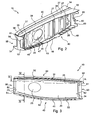
- the plane 1 shown on the figure 1 comprises a fuselage 2 of generally oval section, which protrudes in the middle part, two symmetrical wings 3 and 4. Inside the fuselage 2, a central wing box 5 makes it possible to secure the wings 3 and 4 to the fuselage 2.
- the box 5 comprises an extrados panel 6 and a panel intrados 7 parallel to one another and oriented horizontally.
- the two panels 6 and 7 are fixed by means of two longitudinal front and rear rails 8 and 9 vertical.
- the box 5 also comprises at its two interfaces with the wings 3 and 4, two symmetrical structural elements 10 and 11 in that the structural element 10 is attached to the wing 3 while the element 11 is attached to the wing 4.
- These two structural elements 10 and 11 extend vertically between the two panels 6 and 7 and longitudinally between the two front longitudinal members 8 and 9.
- the structural element 10 comprises a web 20 made of an aluminum alloy containing lithium.
- the incorporation of lithium whose density is lower than that of aluminum, provides a weight saving of the order of 5% while also improving weldability and damage tolerance.
- the contour of the web 20 is generally rectangular and has two parallel rectilinear portions which are connected by two curved portions towards the outside.
- This web 20 has peripherally four flat portions 21, 22, 23 and 24 coplanar and each extending the entire length of a respective side.
- portion 21 (respectively, the portion 22) located near the extrados panel 6 (respectively, the intrados panel 7) is referred to as upper portion 21 (lower portion 22 respectively).
- portion 23 located near the front spar 8 (respectively, the rear spar 9) is referred to as front portion 23 (respectively rear portion 24).
- this web 20 has a ratio between length and width of approximately 4 to 1 (see figure 3 ). More generally, the web 20 is at least twice as long as it is wide.
- An oval opening 25 oriented horizontally is disposed halfway of the web 20 in its front half.
- the web 20 also has on a first face 26, three metal stiffeners 27 which extend vertically over its entire height.
- the first stiffener 27 is located near the front portion 23, the second stiffener 27 being disposed symmetrically with respect to the first vis-à-vis the opening 25.
- the third stiffener 27 is located, meanwhile, near the rear part 24.
- stiffeners 27 project transversely to the plane in which the four parts 21, 22, 23 and 24 extend. The presence of these stiffeners 27 provides better resistance to the flat portions 21, 22, 23 and 24 and more generally to the entire web 20.
- the second face of the central web 20 (not visible in the drawings) has five metal frame legs which are arranged vertically on either side of the opening 25.
- the structural element 10 also comprises four elements 30, 40, 50 and 60 which border the four sides of the web 20.
- these elements 30, 40, 50 and 60 are made of the same aluminum alloy However, depending on the constraints and requirements of each of these elements 30, 40, 50 and 60, these can be obtained from aluminum alloys different from that constituting the web 20. This allows to optimize the cost and the mass of the structural element 10 by choosing for each constituent element, the most suitable material according to the constraints and necessities.
- the first element 30 which borders the upper side of the web 20, is generally profiled in a slightly curved direction and has a cross section which varies slightly from its front end to its rear end.
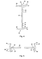
- the profiled element 30 comprises a first flat fin 31 which is arranged without overlap in the extension of the upper portion 21 and connected thereto by a curved weld bead 32 end to end friction stir.
- the weld bead 32 extends uninterrupted over a length at least equal to 95% of the length of the upper side of the web 20, but does not reach both its front and rear ends.
- the profiled element 30 also comprises a second fin 33 and a slightly convex third fin 34, arranged on either side of the first fin 31. These fins 33 and 34 take root along the curved end of the fin 31 located opposite the weld bead 32. A fourth flat fin 39 is disposed in the extension of the first fin 31.
- the fin 33 has a slice which extends slightly obliquely to the edge of the fin 39 and towards the upper surface of the wing 3 to which the fin 33 is attached.
- the edge of the fin 34 extends opposite the edge of the fin 33, perpendicular to the edge of the fin 31 and towards the structural element 11.
- the fin 33 has on its first two thirds before, a first portion 35 of substantially constant width (taken in the direction of the central box 5 to the wing 3).
- the fin 33 is extended by a second portion 37 whose width increases steadily up to its rear end.
- the fin 34 also has on its first two thirds before, a first portion 36 of substantially constant width (taken in the direction of the central box 5 to the wing 3).
- the fin 34 is extended by a second portion 38 whose width increases steadily to its rear end.
- the fin 39 has a free edge of the same curvature as the weld bead 32.
- the second element 40 which borders the lower side of the web 20, is generally profiled in a slightly curved direction.
- the profiled element 40 comprises a first flat fin 41 of constant width (taken in the direction of the element 40 towards the element 30) which is arranged without overlap in the extension of the lower part 22 and connected thereto by a curved weld bead 42 butt friction stir.
- the weld bead 42 extends uninterrupted over a length at least equal to 95% of the length of the lower side of the web 20, without reaching its two front and rear ends.
- the profiled element 40 also comprises a second fin 43 and a third fin 44 curved, disposed on either side of the first fin 41. These fins 43 and 44 take root all along the curved end of the fin 41 located opposite the weld bead 42.
- the fin 43 has a slice which extends slightly obliquely towards the edge of the fin 41 and towards the end of the flange 3.
- the edge of the fin 44 extends opposite the edge of the fin 43 perpendicular to the edge of the fin 41 and towards the structural element 11.
- fin 43 has two front portions 45 and rear 46 crenellated.
- Each slot 47 which has an outline M consists of two identical fingers contiguous.
- the front 45 and rear 46 portions are separated by a central portion 48 having a generally rectilinear free edge intersected at the first and second third of its length by a pair of saw teeth.
- the fin 44 (not visible on the figure 2 ) also comprises two front and rear portions, crenellated and each slot which has a contour M, consists of two identical fingers joined. These crenellated portions facilitate the attachment of the structural element to the other components of the aircraft (wing and wing central box).
- the third element 50 which borders the front side of the web 20, is profiled in a rectilinear direction.
- the profiled element 50 comprises a first blade 51 of constant width (taken in the direction of the element 50 towards the element 60) which is arranged without overlap in the extension of the front portion 23 and connected thereto by a rectilinear weld seam 52 butt friction stir.
- the weld bead 52 extends uninterrupted for a length at least equal to 95% of the length the front side of the web 20, without reaching its two upper and lower ends.
- the profiled element 50 also comprises a second fin 53 and a third fin 54, arranged on either side of the first fin 51. These fins 53 and 54 take root along the straight end of the fin 51. located opposite the weld seam 52.
- the fins 53 and 54 have slices forming a very flared V facing the web 20 and whose tip is at the junction of the three slices of the fins 51, 53 and 54.
- the edge of the fin 53 extends towards the front of the wing 3 to which the fin 53 is attached.
- the edge of the fin 54 extends towards the front spar 8 of the central box 5 to which the fin 54 is attached.
- fin 53 has a notch defining a narrower central portion 55 which runs over about two-thirds of fin 53 and has a generally rectilinear profile parallel to weld bead 52.
- the fin 54 also has a narrower central portion 56 which runs over approximately two-thirds of the fin 54 and has a generally rectilinear profile parallel to the weld bead 52.
- the fourth element 60 which borders the rear side of the web 20, is profiled in a rectilinear direction.
- the profiled element 60 comprises a first blade 61 of constant width (taken in the direction of the element 50 towards the element 60) which is arranged without overlap in the extension of the rear portion 24 and connected thereto by a rectilinear weld bead 62 butt friction stir.
- the weld bead 62 extends uninterrupted over a length of at least 95% of the length of the rear side of the web 20, without however reaching its two upper and lower ends.
- the profiled element 60 also comprises a second fin 63 and a third fin 64 flat, arranged on either side of the first fin 61. These fins 63 and 64 take root along the straight end of the fin 61 located opposite the weld bead 62.
- the fins 63 and 64 have slices forming a very flared V facing the web 20 and whose tip is at the junction of the three slices of the fins 61, 63 and 64.
- the edge of the fin 63 extends towards the rear of the wing 3 to which the fin 63 is attached.
- the edge of the fin 64 extends towards the rear spar 9 of the central box 5 to which the fin 64 is attached.
- the fin 63 has indentations defining a narrower central portion 65 which runs over two-thirds of the fin 63 and has a non-homogeneous profile.
- This profile has a first upper portion rectilinear and parallel to the weld bead 62 which is extended by a second sawtooth portion.
- the winglet 64 (not visible on the figure 2 ), also has a narrower central portion which runs over two-thirds of the fin 64 and has a non-homogeneous profile similar to that of the indented portion 65.
- the curved weld seams 32 and 42 and the straight weld seams 52 and 62 follow (or resume) the contour of the web 20.
- these four beads 32, 42, 52 and 62 are not joined at the corners of the veil 20.
- each of the four profiled elements 30, 40, 50 and 60 is first positioned around the web 20 so that the fin 31 (respectively 41, 51 and 61) of the profiled element 30 (respectively 40, 50 and 60) is in the same plane and in end-to-end relation with the flat part 21 (respectively 22 , 23 and 24) of the web 20, thus forming a joining line.
- the profiled friction element 30, 40, 50 and 60 is kneaded together by friction friction to the web 20 along the corresponding joint line in order to plasticize the metal in the weld zone.
- one or more of the elements such as 30, 40, 50 and 60 are profiled differently, for example in a rectilinear direction, with the weld seams such as 32, 42, 52 and 62 which are also rectilinear.
Landscapes
- Engineering & Computer Science (AREA)
- Mechanical Engineering (AREA)
- Aviation & Aerospace Engineering (AREA)
- Pressure Welding/Diffusion-Bonding (AREA)
- Braking Arrangements (AREA)
- Connection Of Plates (AREA)
Claims (14)
- Strukturelement eines Luftfahrzeugs (1), das an einer Schnittstelle zwischen einem Flügel (3) und dem Rumpf (2) des Luftfahrzeugs (1) gelegen ist und eine Schale (20) und Profilelemente (30, 40, 50, 60), die die Schale (20) einfassen, umfasst,
dadurch gekennzeichnet, dass das Strukturelement einen Teil eines zentralen Kastens (5) der Tragfläche des Luftfahrzeugs (1) bildet, wobei der zentrale Kasten (5) im Inneren des Rumpfes (2) angeordnet ist, und dass zumindest ein Profilelement (30, 40, 50, 60) einen ebenen Teil (31, 41, 51, 61) umfasst, der ohne Überlappung in der Verlängerung eines ebenen Teils (21, 22, 23, 24) der Schale (20) angeordnet und mit diesem durch eine Reibrühr-Stumpfschweißnaht (32, 42, 52, 62) verbunden ist. - Element nach Anspruch 1,
dadurch gekennzeichnet, dass die Schweißnaht (32, 42) gekrümmt ist. - Element nach Anspruch 1,
dadurch gekennzeichnet, dass die Schweißnaht (52, 62) gerade ist. - Element nach einem der Ansprüche 1 bis 3,
dadurch gekennzeichnet, dass die Schale (20) zumindest eine Seite umfasst, auf der sich die Schweißnaht (32, 42, 52, 62) auf eine ununterbrochene Weise über eine Länge von zumindest 95 % der Länge der Seite erstreckt. - Element nach einem der Ansprüche 1 bis 4,
dadurch gekennzeichnet, dass das Profilelement (30, 40, 50, 60) zudem eine erste Rippe (31, 41, 51, 61), die den ebenen Teil bildet, eine zweite Rippe (33, 43, 53, 63) und eine dritte Rippe (34, 44, 54, 64) umfasst, die jeweils entlang der ersten Rippe (31, 41, 51, 61) entgegengesetzt zu der Schweißnaht (32, 42, 52, 62) verlaufen, wobei die zweite Rippe (33, 43, 53, 63) und die dritte Rippe (34, 44, 54, 64) beiderseits der ersten Rippe (31, 41, 51, 61) angeordnet sind. - Element nach Anspruch 5,
dadurch gekennzeichnet, dass das Profilelement (30) zusätzlich zu der ersten, zweiten und dritten Rippen (31, 33, 34) eine vierte Rippe (39) umfasst, die entgegengesetzt zu der ersten Rippe (31) angeordnet ist. - Element nach einem der Ansprüche 5 oder 6,
dadurch gekennzeichnet, dass zumindest eine von der zweiten und dritten Rippen (33, 34) des Profilelements (30) einen Abschnitt (37, 38) umfasst, dessen Breite sich gleichmäßig ändert. - Element nach einem der Ansprüche 5 oder 6,
dadurch gekennzeichnet, dass zumindest eine von der zweiten und dritten Rippen (43, 44) des Profilelements (40) einen gezackten Abschnitt (45, 46) umfasst, von dem jede Zacke (47) aus zwei miteinander verbundenen Fingern gebildet ist. - Element nach einem der Ansprüche 5 oder 6,
dadurch gekennzeichnet, dass zumindest eine von der zweiten und dritten Rippen (53, 63, 54, 64) des Profilelements (50, 60) einen schmaleren Abschnitt (55, 56, 65) umfasst. - Element nach einem der Ansprüche 1 bis 9,
dadurch gekennzeichnet, dass die Schale (20) auf zumindest einer Fläche einen Abschnitt (27) umfasst, der bezüglich des ebenen Teils (21 - 24) vorsteht. - Element nach einem der Ansprüche 1 bis 10,
dadurch gekennzeichnet, dass die Schale (20) auf jeder Seite einen ebenen Teil (21 - 24) umfasst, der sich über die gesamte Länge dieser Seite erstreckt. - Element nach einem der Ansprüche 1 bis 11,
dadurch gekennzeichnet, dass die Schale (20) eine im Allgemeinen rechteckige Form aufweist und mindestens zweimal länger als breit ist. - Element nach einem der Ansprüche 1 bis 12,
dadurch gekennzeichnet, dass die Schale (20) und das Profilelement aus der gleichen Lithium enthaltenden Aluminiumlegierung realisiert sind. - Element nach einem der Ansprüche 1 bis 12,
dadurch gekennzeichnet, dass die Schale (20) und das Profilelement aus unterschiedlichen Aluminiumlegierungen realisiert sind.
Applications Claiming Priority (2)
| Application Number | Priority Date | Filing Date | Title |
|---|---|---|---|
| FR0755228A FR2916417B1 (fr) | 2007-05-23 | 2007-05-23 | Element structural d'aeronef situe a l'interface entre une aile et le fuselage |
| PCT/FR2008/000662 WO2008152248A2 (fr) | 2007-05-23 | 2008-05-13 | Élément structural d'aéronef situé à l'interface entre une aile et le fuselage |
Publications (2)
| Publication Number | Publication Date |
|---|---|
| EP2178746A2 EP2178746A2 (de) | 2010-04-28 |
| EP2178746B1 true EP2178746B1 (de) | 2012-09-05 |
Family
ID=38754582
Family Applications (1)
| Application Number | Title | Priority Date | Filing Date |
|---|---|---|---|
| EP08805566A Not-in-force EP2178746B1 (de) | 2007-05-23 | 2008-05-13 | An der schnittstelle zwischen einem flügel und dem rumpf eines flugzeugs positioniertes strukturelement |
Country Status (10)
| Country | Link |
|---|---|
| US (1) | US8720823B2 (de) |
| EP (1) | EP2178746B1 (de) |
| JP (1) | JP5373773B2 (de) |
| KR (1) | KR20100068231A (de) |
| CN (1) | CN101687541B (de) |
| BR (1) | BRPI0810287A2 (de) |
| CA (1) | CA2687437C (de) |
| FR (1) | FR2916417B1 (de) |
| RU (1) | RU2478519C2 (de) |
| WO (1) | WO2008152248A2 (de) |
Families Citing this family (16)
| Publication number | Priority date | Publication date | Assignee | Title |
|---|---|---|---|---|
| FR2916417B1 (fr) * | 2007-05-23 | 2009-07-24 | Airbus France Sas | Element structural d'aeronef situe a l'interface entre une aile et le fuselage |
| ES2351823B1 (es) * | 2007-12-21 | 2011-12-05 | Airbus Operations, S.L. | Estructura sustentadora para aeronaves. |
| ES2392617B1 (es) * | 2010-01-15 | 2013-11-21 | Airbus Operations S.L. | Disposición de unión de los cajones laterales de un estabilizador horizontal de cola con un cajón central tubular y procedimiento de fabricación de dicho cajón. |
| ES2372849B1 (es) * | 2010-03-25 | 2012-12-13 | Airbus Operations, S.L. | Estructura de unión de cajones de torsión en una aeronave mediante un herraje triforme de materiales compuestos no metálicos. |
| GB201009922D0 (en) | 2010-06-14 | 2010-07-21 | Airbus Uk Ltd | Aircraft wing box joint |
| FR2972997B1 (fr) | 2011-03-25 | 2013-05-10 | Airbus Operations Sas | Raccordement d'un fuselage a une voilure d'aeronef |
| GB201110973D0 (en) * | 2011-06-28 | 2011-08-10 | Airbus Operations Ltd | Bracket |
| FR2991228B1 (fr) | 2012-05-29 | 2015-03-06 | Airbus Operations Sas | Procede et dispositif de realisation d'un panneau composite auto-raidi |
| US10118686B2 (en) | 2012-09-27 | 2018-11-06 | The Boeing Company | Wing root insert system for an aircraft family |
| GB201217801D0 (en) | 2012-10-05 | 2012-11-14 | Airbus Operations Ltd | An aircraft structure |
| US9315254B2 (en) * | 2013-10-11 | 2016-04-19 | The Boeing Company | Joint assembly and method of assembling same |
| FR3040684A1 (fr) * | 2015-09-04 | 2017-03-10 | Airbus Operations Sas | Nervure simplifiee pour caisson central de voilure d'aeronef. |
| RU2621925C1 (ru) * | 2016-01-28 | 2017-06-08 | Публичное акционерное Общество "Таганрогский авиационный научно-технический комплекс им. Г.М. Бериева" (ПАО "ТАНТК им. Г.М. Бериева") | Стык консоли крыла с центропланом самолета |
| US10479474B2 (en) | 2016-07-14 | 2019-11-19 | The Boeing Company | Friction stir welded wingtip torque box |
| FR3074143A1 (fr) * | 2017-11-29 | 2019-05-31 | Airbus Operations | Nervure de jonction voilure-caisson de voilure pour aeronef et procede de fabrication d'un aeronef au moyen d'une telle nervure |
| US11358703B2 (en) * | 2020-03-18 | 2022-06-14 | The Boeing Company | Monolithic wing to side body upper chord assembly for aircraft |
Family Cites Families (23)
| Publication number | Priority date | Publication date | Assignee | Title |
|---|---|---|---|---|
| US2116953A (en) * | 1934-09-07 | 1938-05-10 | Sambraus Adolf | Airplane structure |
| US2210163A (en) * | 1938-03-07 | 1940-08-06 | Ryan Aeronautical Co | Airplane wing and wing spar |
| US2318909A (en) * | 1940-10-02 | 1943-05-11 | Bell Aircraft Corp | Wing construction |
| US2367750A (en) * | 1941-01-17 | 1945-01-23 | Central Aircraft Corp | Aircraft construction |
| US2396625A (en) * | 1941-03-26 | 1946-03-12 | Budd Edward G Mfg Co | Aircraft structure |
| US2618448A (en) * | 1941-12-12 | 1952-11-18 | Robert Roger Aime | Structure for airplane wings |
| US2393081A (en) * | 1943-06-28 | 1946-01-15 | Budd Edward G Mfg Co | Joint construction |
| FR1523404A (fr) * | 1967-03-22 | 1968-05-03 | Sud Aviation | Perfectionnement aux raccordements entre fuselage et voilure d'un aérodyne |
| US5297760A (en) * | 1992-08-21 | 1994-03-29 | Mcdonnell Douglas Corporation | Aircraft skin lap splice |
| CN1204288A (zh) * | 1995-12-15 | 1999-01-06 | 波音公司 | 多用途通用机体基本结构的飞机 |
| US6314630B1 (en) * | 1996-03-22 | 2001-11-13 | The Boeing Company | Determinant wing assembly |
| US7509740B2 (en) * | 2001-11-13 | 2009-03-31 | The Boeing Company | Method of manufacturing a wing |
| GB9713209D0 (en) * | 1997-06-20 | 1997-08-27 | British Aerospace | Friction welding metal components |
| US6116539A (en) * | 1999-03-19 | 2000-09-12 | Williams International Co. L.L.C. | Aeroelastically stable forward swept wing |
| US6398883B1 (en) * | 2000-06-07 | 2002-06-04 | The Boeing Company | Friction stir grain refinement of structural members |
| US20030226935A1 (en) * | 2001-11-02 | 2003-12-11 | Garratt Matthew D. | Structural members having improved resistance to fatigue crack growth |
| GB2409443A (en) * | 2003-12-23 | 2005-06-29 | Airbus Uk Ltd | Rib for an aircraft and the manufacture thereof |
| ATE431770T1 (de) * | 2004-09-14 | 2009-06-15 | Alcan Rhenalu | Geschweisstes strukturelement mit mindestens zwei aluminiumlegierungsteilen, die verschiedene metallurgische zustände haben, und verfahren zur herstellung solch eines elements |
| CA2529108C (en) * | 2004-12-07 | 2012-10-30 | Airbus Deutschland Gmbh | Airplane wing, method for manufacturing an airplane wing and use of a welding process for welding a wing spar |
| FR2894859A1 (fr) * | 2005-12-16 | 2007-06-22 | Alcan Rhenalu Sa | Longeron de voilure soude et son procede de fabrication |
| GB0606079D0 (en) * | 2006-03-27 | 2006-05-03 | Airbus Uk Ltd | Aircraft component |
| FR2916417B1 (fr) * | 2007-05-23 | 2009-07-24 | Airbus France Sas | Element structural d'aeronef situe a l'interface entre une aile et le fuselage |
| BRPI0915440B1 (pt) * | 2008-07-07 | 2017-11-14 | Constellium Switzerland Ag | Process of fusion welding to join aluminum and titanium and joint submitted to brazing |
-
2007
- 2007-05-23 FR FR0755228A patent/FR2916417B1/fr not_active Expired - Fee Related
-
2008
- 2008-05-13 WO PCT/FR2008/000662 patent/WO2008152248A2/fr not_active Ceased
- 2008-05-13 BR BRPI0810287-2A2A patent/BRPI0810287A2/pt not_active IP Right Cessation
- 2008-05-13 US US12/601,170 patent/US8720823B2/en active Active
- 2008-05-13 KR KR1020097026309A patent/KR20100068231A/ko not_active Ceased
- 2008-05-13 JP JP2010508874A patent/JP5373773B2/ja not_active Expired - Fee Related
- 2008-05-13 CA CA2687437A patent/CA2687437C/en not_active Expired - Fee Related
- 2008-05-13 EP EP08805566A patent/EP2178746B1/de not_active Not-in-force
- 2008-05-13 CN CN2008800169366A patent/CN101687541B/zh not_active Expired - Fee Related
- 2008-05-13 RU RU2009147734/11A patent/RU2478519C2/ru not_active IP Right Cessation
Also Published As
| Publication number | Publication date |
|---|---|
| RU2478519C2 (ru) | 2013-04-10 |
| CN101687541A (zh) | 2010-03-31 |
| FR2916417A1 (fr) | 2008-11-28 |
| US8720823B2 (en) | 2014-05-13 |
| JP5373773B2 (ja) | 2013-12-18 |
| CA2687437C (en) | 2015-12-08 |
| WO2008152248A8 (fr) | 2010-04-22 |
| JP2010527832A (ja) | 2010-08-19 |
| US20100170986A1 (en) | 2010-07-08 |
| CA2687437A1 (en) | 2008-12-18 |
| WO2008152248A3 (fr) | 2009-02-12 |
| EP2178746A2 (de) | 2010-04-28 |
| FR2916417B1 (fr) | 2009-07-24 |
| RU2009147734A (ru) | 2011-06-27 |
| BRPI0810287A2 (pt) | 2014-12-30 |
| WO2008152248A2 (fr) | 2008-12-18 |
| KR20100068231A (ko) | 2010-06-22 |
| CN101687541B (zh) | 2013-02-13 |
Similar Documents
| Publication | Publication Date | Title |
|---|---|---|
| EP2178746B1 (de) | An der schnittstelle zwischen einem flügel und dem rumpf eines flugzeugs positioniertes strukturelement | |
| CA2585869C (fr) | Cadre de structure de fuselage d'aeronef | |
| CA2702908C (fr) | Structure d'avion comportant des jonctions d'arrets de raidisseurs | |
| EP2218641B1 (de) | Rückströmungnetzwerkelement für Flugzeuge | |
| FR2911096A1 (fr) | Structure de siege de vehicule et siege comportant une telle structure | |
| FR3076282A1 (fr) | Ensemble pour aeronef comprenant une structure primaire de mat d'accrochage fixee a un caisson de voilure par des attaches presentant un encombrement reduit dans la zone de bord d'attaque | |
| FR3073824A1 (fr) | Ensemble pour aeronef comprenant une structure primaire de mat d'accrochage fixee a un caisson de voilure par des attaches partiellement enterrees dans la structure primaire | |
| EP3699091B1 (de) | Primärstruktur eines flugzeugtriebwerkträgers, die mindestens eine querversteifung mit zwei diagonal angeordneten streben umfasst, und luftfahrzeug mit einer solchen primärstruktur | |
| EP1571079B1 (de) | Rumpfholm für ein Flugzeug und Flügelmittelkasten mit einem solchen Rumpfholm | |
| EP2264324A1 (de) | Verfahren zur Herstellung einer Gelenkstange für den Flugzeugbau | |
| FR2943317A1 (fr) | Procede de fabrication d'une levre d'entree d'air pour nacelle d'aeronef | |
| EP3674205A1 (de) | Vorflügel mit optimierter struktur | |
| EP4344994B1 (de) | Verfahren zum verbinden eines rumpfteils durch schweissen mit verbesserter flexibilität, rumpfteil und so erhaltenes luftfahrzeug | |
| EP4570647A1 (de) | Vorrichtung zur absorption von energie durch kompression, luftfahrzeug, das mindestens eine solche vorrichtung umfasst | |
| EP4112477B1 (de) | Flugzeug-propellerbaugruppe, die eine vordere motorbefestigung umfasst, die einen querträger umfasst, der teilweise mit einer vorderen querverstärkung einer primärstruktur eines masts positioniert ist | |
| FR3101611A1 (fr) | Panneau renforcé à structure alvéolaire comprenant au moins une zone de liaison présentant une surépaisseur et aéronef comprenant au moins un tel panneau renforcé | |
| FR3101064A1 (fr) | Procédé d’assemblage d’une structure primaire d’un mât d’aéronef, structure primaire d’un mât d’aéronef ainsi obtenue et aéronef comprenant ladite structure primaire | |
| WO2016124730A1 (fr) | Procede de realisation de panneau a raidissement croise par soudage par friction malaxage et structure d'avion formee a partir d'un tel panneau | |
| EP4169797B1 (de) | Karosseriestruktur für ein fahrzeug, insbesondere ein schienenfahrzeug | |
| EP4613649A1 (de) | Primärstruktur eines flugzeugpylons mit dreieckigem querschnitt, flugzeug mit mindestens einer solchen primärstruktur | |
| FR3089442A1 (fr) | Procédé d’assemblage d’au moins deux pièces par soudage par transparence, procédé d’assemblage d’une structure primaire d’un mât d’aéronef par soudage par transparence, structure primaire d’un mât d’aéronef ainsi obtenue et aéronef comprenant ladite structure primaire | |
| EP4467462A1 (de) | Flugzeugverkleidung mit einer demontierbaren platte und einer komprimierbaren dichtung, luftfahrzeug mit mindestens einer solchen verkleidung | |
| EP3098160A1 (de) | Monoblock-aussteifung für flugzeugstruktur | |
| BE370068A (de) | ||
| BE471695A (de) |
Legal Events
| Date | Code | Title | Description |
|---|---|---|---|
| PUAI | Public reference made under article 153(3) epc to a published international application that has entered the european phase |
Free format text: ORIGINAL CODE: 0009012 |
|
| 17P | Request for examination filed |
Effective date: 20091210 |
|
| AK | Designated contracting states |
Kind code of ref document: A2 Designated state(s): AT BE BG CH CY CZ DE DK EE ES FI FR GB GR HR HU IE IS IT LI LT LU LV MC MT NL NO PL PT RO SE SI SK TR |
|
| AX | Request for extension of the european patent |
Extension state: AL BA MK RS |
|
| RIN1 | Information on inventor provided before grant (corrected) |
Inventor name: LAFLY, ANNE-LAURE Inventor name: BATALLA, FRANCK Inventor name: LEMAN, HENRI |
|
| DAX | Request for extension of the european patent (deleted) | ||
| 17Q | First examination report despatched |
Effective date: 20101115 |
|
| GRAP | Despatch of communication of intention to grant a patent |
Free format text: ORIGINAL CODE: EPIDOSNIGR1 |
|
| GRAS | Grant fee paid |
Free format text: ORIGINAL CODE: EPIDOSNIGR3 |
|
| GRAA | (expected) grant |
Free format text: ORIGINAL CODE: 0009210 |
|
| AK | Designated contracting states |
Kind code of ref document: B1 Designated state(s): AT BE BG CH CY CZ DE DK EE ES FI FR GB GR HR HU IE IS IT LI LT LU LV MC MT NL NO PL PT RO SE SI SK TR |
|
| REG | Reference to a national code |
Ref country code: GB Ref legal event code: FG4D Free format text: NOT ENGLISH |
|
| REG | Reference to a national code |
Ref country code: CH Ref legal event code: EP |
|
| REG | Reference to a national code |
Ref country code: AT Ref legal event code: REF Ref document number: 573980 Country of ref document: AT Kind code of ref document: T Effective date: 20120915 |
|
| REG | Reference to a national code |
Ref country code: IE Ref legal event code: FG4D Free format text: LANGUAGE OF EP DOCUMENT: FRENCH |
|
| REG | Reference to a national code |
Ref country code: DE Ref legal event code: R096 Ref document number: 602008018597 Country of ref document: DE Effective date: 20121025 |
|
| REG | Reference to a national code |
Ref country code: AT Ref legal event code: MK05 Ref document number: 573980 Country of ref document: AT Kind code of ref document: T Effective date: 20120905 |
|
| REG | Reference to a national code |
Ref country code: NL Ref legal event code: VDEP Effective date: 20120905 |
|
| PG25 | Lapsed in a contracting state [announced via postgrant information from national office to epo] |
Ref country code: NO Free format text: LAPSE BECAUSE OF FAILURE TO SUBMIT A TRANSLATION OF THE DESCRIPTION OR TO PAY THE FEE WITHIN THE PRESCRIBED TIME-LIMIT Effective date: 20121205 Ref country code: FI Free format text: LAPSE BECAUSE OF FAILURE TO SUBMIT A TRANSLATION OF THE DESCRIPTION OR TO PAY THE FEE WITHIN THE PRESCRIBED TIME-LIMIT Effective date: 20120905 Ref country code: LT Free format text: LAPSE BECAUSE OF FAILURE TO SUBMIT A TRANSLATION OF THE DESCRIPTION OR TO PAY THE FEE WITHIN THE PRESCRIBED TIME-LIMIT Effective date: 20120905 Ref country code: HR Free format text: LAPSE BECAUSE OF FAILURE TO SUBMIT A TRANSLATION OF THE DESCRIPTION OR TO PAY THE FEE WITHIN THE PRESCRIBED TIME-LIMIT Effective date: 20120905 Ref country code: CY Free format text: LAPSE BECAUSE OF FAILURE TO SUBMIT A TRANSLATION OF THE DESCRIPTION OR TO PAY THE FEE WITHIN THE PRESCRIBED TIME-LIMIT Effective date: 20120905 Ref country code: AT Free format text: LAPSE BECAUSE OF FAILURE TO SUBMIT A TRANSLATION OF THE DESCRIPTION OR TO PAY THE FEE WITHIN THE PRESCRIBED TIME-LIMIT Effective date: 20120905 |
|
| REG | Reference to a national code |
Ref country code: LT Ref legal event code: MG4D Effective date: 20120905 |
|
| PG25 | Lapsed in a contracting state [announced via postgrant information from national office to epo] |
Ref country code: GR Free format text: LAPSE BECAUSE OF FAILURE TO SUBMIT A TRANSLATION OF THE DESCRIPTION OR TO PAY THE FEE WITHIN THE PRESCRIBED TIME-LIMIT Effective date: 20121206 Ref country code: SE Free format text: LAPSE BECAUSE OF FAILURE TO SUBMIT A TRANSLATION OF THE DESCRIPTION OR TO PAY THE FEE WITHIN THE PRESCRIBED TIME-LIMIT Effective date: 20120905 Ref country code: SI Free format text: LAPSE BECAUSE OF FAILURE TO SUBMIT A TRANSLATION OF THE DESCRIPTION OR TO PAY THE FEE WITHIN THE PRESCRIBED TIME-LIMIT Effective date: 20120905 Ref country code: LV Free format text: LAPSE BECAUSE OF FAILURE TO SUBMIT A TRANSLATION OF THE DESCRIPTION OR TO PAY THE FEE WITHIN THE PRESCRIBED TIME-LIMIT Effective date: 20120905 |
|
| PG25 | Lapsed in a contracting state [announced via postgrant information from national office to epo] |
Ref country code: EE Free format text: LAPSE BECAUSE OF FAILURE TO SUBMIT A TRANSLATION OF THE DESCRIPTION OR TO PAY THE FEE WITHIN THE PRESCRIBED TIME-LIMIT Effective date: 20120905 Ref country code: NL Free format text: LAPSE BECAUSE OF FAILURE TO SUBMIT A TRANSLATION OF THE DESCRIPTION OR TO PAY THE FEE WITHIN THE PRESCRIBED TIME-LIMIT Effective date: 20120905 Ref country code: CZ Free format text: LAPSE BECAUSE OF FAILURE TO SUBMIT A TRANSLATION OF THE DESCRIPTION OR TO PAY THE FEE WITHIN THE PRESCRIBED TIME-LIMIT Effective date: 20120905 Ref country code: RO Free format text: LAPSE BECAUSE OF FAILURE TO SUBMIT A TRANSLATION OF THE DESCRIPTION OR TO PAY THE FEE WITHIN THE PRESCRIBED TIME-LIMIT Effective date: 20120905 Ref country code: IS Free format text: LAPSE BECAUSE OF FAILURE TO SUBMIT A TRANSLATION OF THE DESCRIPTION OR TO PAY THE FEE WITHIN THE PRESCRIBED TIME-LIMIT Effective date: 20130105 Ref country code: ES Free format text: LAPSE BECAUSE OF FAILURE TO SUBMIT A TRANSLATION OF THE DESCRIPTION OR TO PAY THE FEE WITHIN THE PRESCRIBED TIME-LIMIT Effective date: 20121216 |
|
| PG25 | Lapsed in a contracting state [announced via postgrant information from national office to epo] |
Ref country code: PT Free format text: LAPSE BECAUSE OF FAILURE TO SUBMIT A TRANSLATION OF THE DESCRIPTION OR TO PAY THE FEE WITHIN THE PRESCRIBED TIME-LIMIT Effective date: 20130107 Ref country code: PL Free format text: LAPSE BECAUSE OF FAILURE TO SUBMIT A TRANSLATION OF THE DESCRIPTION OR TO PAY THE FEE WITHIN THE PRESCRIBED TIME-LIMIT Effective date: 20120905 Ref country code: SK Free format text: LAPSE BECAUSE OF FAILURE TO SUBMIT A TRANSLATION OF THE DESCRIPTION OR TO PAY THE FEE WITHIN THE PRESCRIBED TIME-LIMIT Effective date: 20120905 |
|
| PLBE | No opposition filed within time limit |
Free format text: ORIGINAL CODE: 0009261 |
|
| STAA | Information on the status of an ep patent application or granted ep patent |
Free format text: STATUS: NO OPPOSITION FILED WITHIN TIME LIMIT |
|
| PG25 | Lapsed in a contracting state [announced via postgrant information from national office to epo] |
Ref country code: BG Free format text: LAPSE BECAUSE OF FAILURE TO SUBMIT A TRANSLATION OF THE DESCRIPTION OR TO PAY THE FEE WITHIN THE PRESCRIBED TIME-LIMIT Effective date: 20121205 Ref country code: DK Free format text: LAPSE BECAUSE OF FAILURE TO SUBMIT A TRANSLATION OF THE DESCRIPTION OR TO PAY THE FEE WITHIN THE PRESCRIBED TIME-LIMIT Effective date: 20120905 |
|
| 26N | No opposition filed |
Effective date: 20130606 |
|
| PG25 | Lapsed in a contracting state [announced via postgrant information from national office to epo] |
Ref country code: IT Free format text: LAPSE BECAUSE OF FAILURE TO SUBMIT A TRANSLATION OF THE DESCRIPTION OR TO PAY THE FEE WITHIN THE PRESCRIBED TIME-LIMIT Effective date: 20120905 |
|
| REG | Reference to a national code |
Ref country code: DE Ref legal event code: R097 Ref document number: 602008018597 Country of ref document: DE Effective date: 20130606 |
|
| BERE | Be: lapsed |
Owner name: AIRBUS OPERATIONS Effective date: 20130531 |
|
| PG25 | Lapsed in a contracting state [announced via postgrant information from national office to epo] |
Ref country code: MC Free format text: LAPSE BECAUSE OF FAILURE TO SUBMIT A TRANSLATION OF THE DESCRIPTION OR TO PAY THE FEE WITHIN THE PRESCRIBED TIME-LIMIT Effective date: 20120905 |
|
| REG | Reference to a national code |
Ref country code: CH Ref legal event code: PL |
|
| PG25 | Lapsed in a contracting state [announced via postgrant information from national office to epo] |
Ref country code: LI Free format text: LAPSE BECAUSE OF NON-PAYMENT OF DUE FEES Effective date: 20130531 Ref country code: CH Free format text: LAPSE BECAUSE OF NON-PAYMENT OF DUE FEES Effective date: 20130531 |
|
| REG | Reference to a national code |
Ref country code: IE Ref legal event code: MM4A |
|
| PG25 | Lapsed in a contracting state [announced via postgrant information from national office to epo] |
Ref country code: BE Free format text: LAPSE BECAUSE OF NON-PAYMENT OF DUE FEES Effective date: 20130531 |
|
| PG25 | Lapsed in a contracting state [announced via postgrant information from national office to epo] |
Ref country code: IE Free format text: LAPSE BECAUSE OF NON-PAYMENT OF DUE FEES Effective date: 20130513 |
|
| PG25 | Lapsed in a contracting state [announced via postgrant information from national office to epo] |
Ref country code: MT Free format text: LAPSE BECAUSE OF FAILURE TO SUBMIT A TRANSLATION OF THE DESCRIPTION OR TO PAY THE FEE WITHIN THE PRESCRIBED TIME-LIMIT Effective date: 20120905 |
|
| PG25 | Lapsed in a contracting state [announced via postgrant information from national office to epo] |
Ref country code: TR Free format text: LAPSE BECAUSE OF FAILURE TO SUBMIT A TRANSLATION OF THE DESCRIPTION OR TO PAY THE FEE WITHIN THE PRESCRIBED TIME-LIMIT Effective date: 20120905 |
|
| PG25 | Lapsed in a contracting state [announced via postgrant information from national office to epo] |
Ref country code: HU Free format text: LAPSE BECAUSE OF FAILURE TO SUBMIT A TRANSLATION OF THE DESCRIPTION OR TO PAY THE FEE WITHIN THE PRESCRIBED TIME-LIMIT; INVALID AB INITIO Effective date: 20080513 Ref country code: LU Free format text: LAPSE BECAUSE OF NON-PAYMENT OF DUE FEES Effective date: 20130513 |
|
| REG | Reference to a national code |
Ref country code: FR Ref legal event code: PLFP Year of fee payment: 9 |
|
| REG | Reference to a national code |
Ref country code: FR Ref legal event code: PLFP Year of fee payment: 10 |
|
| REG | Reference to a national code |
Ref country code: FR Ref legal event code: PLFP Year of fee payment: 11 |
|
| PGFP | Annual fee paid to national office [announced via postgrant information from national office to epo] |
Ref country code: DE Payment date: 20190521 Year of fee payment: 12 |
|
| REG | Reference to a national code |
Ref country code: DE Ref legal event code: R119 Ref document number: 602008018597 Country of ref document: DE |
|
| PG25 | Lapsed in a contracting state [announced via postgrant information from national office to epo] |
Ref country code: DE Free format text: LAPSE BECAUSE OF NON-PAYMENT OF DUE FEES Effective date: 20201201 |
|
| PGFP | Annual fee paid to national office [announced via postgrant information from national office to epo] |
Ref country code: GB Payment date: 20240521 Year of fee payment: 17 |
|
| PGFP | Annual fee paid to national office [announced via postgrant information from national office to epo] |
Ref country code: FR Payment date: 20240529 Year of fee payment: 17 |
|
| GBPC | Gb: european patent ceased through non-payment of renewal fee |
Effective date: 20250513 |
|
| PG25 | Lapsed in a contracting state [announced via postgrant information from national office to epo] |
Ref country code: GB Free format text: LAPSE BECAUSE OF NON-PAYMENT OF DUE FEES Effective date: 20250513 |
|
| PG25 | Lapsed in a contracting state [announced via postgrant information from national office to epo] |
Ref country code: FR Free format text: LAPSE BECAUSE OF NON-PAYMENT OF DUE FEES Effective date: 20250531 |