EP2179706B1 - Plaquette servant à la fabrication d'une prothèse dentaire - Google Patents
Plaquette servant à la fabrication d'une prothèse dentaire Download PDFInfo
- Publication number
- EP2179706B1 EP2179706B1 EP09173755A EP09173755A EP2179706B1 EP 2179706 B1 EP2179706 B1 EP 2179706B1 EP 09173755 A EP09173755 A EP 09173755A EP 09173755 A EP09173755 A EP 09173755A EP 2179706 B1 EP2179706 B1 EP 2179706B1
- Authority
- EP
- European Patent Office
- Prior art keywords
- plate
- base
- teeth
- plate according
- flat surface
- Prior art date
- Legal status (The legal status is an assumption and is not a legal conclusion. Google has not performed a legal analysis and makes no representation as to the accuracy of the status listed.)
- Not-in-force
Links
- 238000004519 manufacturing process Methods 0.000 title claims description 7
- 239000000463 material Substances 0.000 claims abstract description 15
- 210000004283 incisor Anatomy 0.000 claims abstract description 13
- 230000001720 vestibular Effects 0.000 claims abstract description 10
- 238000000034 method Methods 0.000 claims description 5
- 238000012360 testing method Methods 0.000 claims description 5
- 239000004925 Acrylic resin Substances 0.000 claims description 2
- 229920000178 Acrylic resin Polymers 0.000 claims description 2
- 210000003464 cuspid Anatomy 0.000 claims description 2
- 210000004877 mucosa Anatomy 0.000 claims description 2
- 239000011347 resin Substances 0.000 description 9
- 229920005989 resin Polymers 0.000 description 9
- 210000000214 mouth Anatomy 0.000 description 7
- 230000000877 morphologic effect Effects 0.000 description 5
- 208000006386 Bone Resorption Diseases 0.000 description 3
- 230000024279 bone resorption Effects 0.000 description 3
- 230000000694 effects Effects 0.000 description 2
- 230000006978 adaptation Effects 0.000 description 1
- 238000007792 addition Methods 0.000 description 1
- 230000015572 biosynthetic process Effects 0.000 description 1
- 210000000988 bone and bone Anatomy 0.000 description 1
- 239000000805 composite resin Substances 0.000 description 1
- 238000007796 conventional method Methods 0.000 description 1
- 238000005520 cutting process Methods 0.000 description 1
- 210000002455 dental arch Anatomy 0.000 description 1
- 238000000605 extraction Methods 0.000 description 1
- 210000000887 face Anatomy 0.000 description 1
- 238000005755 formation reaction Methods 0.000 description 1
- 230000014509 gene expression Effects 0.000 description 1
- 229910052736 halogen Inorganic materials 0.000 description 1
- 150000002367 halogens Chemical class 0.000 description 1
- 210000001847 jaw Anatomy 0.000 description 1
- 230000014759 maintenance of location Effects 0.000 description 1
- 210000002050 maxilla Anatomy 0.000 description 1
- 238000005259 measurement Methods 0.000 description 1
- 229920001296 polysiloxane Polymers 0.000 description 1
- 238000003825 pressing Methods 0.000 description 1
- 238000007493 shaping process Methods 0.000 description 1
- 238000012546 transfer Methods 0.000 description 1
Images
Classifications
-
- A—HUMAN NECESSITIES
- A61—MEDICAL OR VETERINARY SCIENCE; HYGIENE
- A61C—DENTISTRY; APPARATUS OR METHODS FOR ORAL OR DENTAL HYGIENE
- A61C13/00—Dental prostheses; Making same
- A61C13/01—Palates or other bases or supports for the artificial teeth; Making same
Definitions
- the present invention refers to a plate element for the manufacture of a maxillary dental prosthesis. More specifically, the invention concerns a curved plate element and a method for the positioning and modelling of a malleable material capable of temporarily supporting the incisor and molar teeth according to positions and orientations that will then be fixed permanently in the prosthesis.
- the dental technician builds two so-called "bases" from resin each having a face carrying the impression of one of the two maxillary and mandibular edentulous arches.
- bases On the face of each base opposite the one having the impression one or more wax rims are applied, which simulate in position and size the dental arches and which act as a malleable and temporary support for the artificial teeth (incisor and molar teeth) that will make up the prosthesis.
- Each base provided with the relative wax rim, is inserted into the edentulous patient's mouth.
- the dentist must shape the rim with particular precision according to the distance between the edentulous arches and certain anthropometric parameters (bi-pupillary plane and Camper's sagittal plane), since the contour of the rim has a determinant effect on the orientation of the occlusal plane of the prosthesis. It is also necessary for the rim to be correctly oriented in relation to other morphological planes (e.g. with respect to the bi-pupillary plane and with respect to the so-called Camper's plane), and for it to visibly project by a few millimetres (typically by 5 mm) from the lip in the position known as "open rest".
- the dentist In order to align the rim correctly and precisely, as well as in relatively short time periods, the dentist needs to have a substantial amount of experience. In fact, in order to shape the rim to the patient, the dentist must cut away wax from the rim to remove it in the areas where it is necessary to make the rim lower, and add wax (which is heated in advance) for the points where, on the other hand, it is necessary to increase the height of the rim, until the ideal position and orientation of the rim are found in the patient's mouth. The position of the rim should also be adjusted with precision in the three dimensions of space, so that the dental prosthesis does not project too far, or is not too recessed, or otherwise misaligned.
- US-A-4 906 186 discloses a curved plate for the manufacture of a maxillary dental prosthesis, in particular a set of two curved plates arranged on a base plate and used for the manufacture of a maxillary dental prosthesis.
- the two curved plates have a general U-shaped form, delimitated by two substantially parabola-shaped contours, with an outer edge corresponding to the contour of the vestibular walls of the incisor and molar teeth of the prosthesis to be built, and an inner edge corresponding to the contour of the lingual walls of said teeth.
- the plate has a flat portion on its lower face, and the base plate defines a visible reference point corresponding to the position of the interincisive papilla.
- a primary object of the present invention is to make a device that at the same time complies with the double requirement of
- Another object of the invention is to reduce the clinical times needed to make prostheses, and in particular to reduce the number of sittings needed at the dentist, the discomfort of the patient, as well as the costs incurred by them.
- a further object of the invention is to precisely transfer the morphological data from the oral cavity of the patient to the prosthesis support, in a way practically independent from the degree of bone resorption reached by the patient.
- Yet another object of the invention is to simplify and optimise the laboratory operations for detecting the morphological data of the oral cavity of the patient, possibly also reducing the number of people involved overall in these activities.
- reference numeral 10 indicates as a unit a testing base, consisting of a rigid body of a substantially uniform thickness that provides on its upper face 11 the impression of the edentulous maxillary arch of the patient. A certain amount of material with a malleable plastic consistency is applied on the opposite lower face 12, as described later on.
- terms and expressions indicating positions and orientations such as “upper”, “lower”, “front”, “rear”, inner” and “outer” are to be interpreted with reference to the mouth of a patient, unless stated otherwise.
- the base 10 is inverted.
- a testing base of the type considered here can, for example, be made from a material that is photopolymerised after having detected the impression of the edentulous arch, as described in EP-A-2 030 585 .
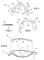
- reference numeral 20 indicates a rigid or relatively rigid plate having an overall U-shape and preferably made from a plastic material, more preferably acrylic resin.
- One of the two faces of the plate 20, in this case the lower face (with reference to its intended use) features a flat surface 21, in which two blind vertical recesses 22 are formed, each situated in one of the respective left and right branches of the plate.
- the plate 20 is delimited by two substantially parabola-shaped contours: an outer edge 23, which will substantially correspond to the vestibular contour of the teeth of the prosthesis to be built, and an inner edge 24, which will substantially correspond to the lingual contour and that also features an appendix 25 the projects rearward from its front segment.
- the appendix has an apex 26 that constitutes a clearly visible reference point capable of corresponding to the position of the interincisive papilla.
- the position of the interincisive papilla generally does not vary appreciably following extractions or even in the presence of accentuated bone resorption that, as known, varies from one individual to the next.
- the outer edge or vestibular contour 23 has a segment 23a at the front with a substantially elliptical arc shape, where three reference points are highlighted, in this example in the form of small notches: a central notch 24a that defines the position of the fraenulum at an intermediate point between the vestibular surfaces of the central incisor teeth, and two notches 24b, 24c, in the positions of the reference axes of the right and left canine teeth.
- the distance "d" between the apex 26 of the appendix 25 and the central point of the outer edge 23 where the notch 24a is formed, is between 8 and 10 mm, and it is preferably 9 mm. This is the average anatomical distance that, in each individual person, separates the interincisive papilla from an ideal surface that envelopes the more vestibular walls of the upper central incisor teeth. With regard to the other dimensions of the plate 20, it should be understood that it can be shaped according to tighter or wider parabolas, according to the general morphology of the patient.
- the plate 20 is used as follows. First of all the dentist detects the position P of the interincisive papilla and highlights it with a pen on the lower face 12 of the base 10. The plate 20 is then rested on the lower face 12 of the base, making the apex 26 of the appendix 25 coincide with the previously marked position P.
- the plate 20 is then oriented angularly on the base 10 so as to align its left and right branches with the respective reliefs of the base that indicate the corresponding segments of the edentulous maxillary arch.
- the outline of the plate 20 is then traced on the lower face 12 of the base with a pen; in other words, the inner and outer edges of the plate 20 are marked on the face 12 so as to outline on the latter the borders of a curved area 13 in which all the incisor and pinless teeth will then be positioned.
- the outline thus marked defines the position of the teeth of the prosthesis with reference to the interincisive papilla: this reference ensures that the teeth of the prosthesis will be positioned in a correct and clinically acceptable manner, in the patient's mouth, no matter what the degree of bone resorption reached. In other words, the arch of the molars of the maxilla will be located with a clinically acceptable approximation in the same position as that of the original teeth.
- a strip of malleable resin 30 of plastic consistency having a height of about 1-2 cm is then applied onto the curved area 13, on the lower face 12 of the base.
- the material constituting the strip 30 is preferably a composite resin able to be photopolymerised by exposure to ultraviolet light (wavelength 350-400 nm) or halogen (wavelength 420-480 nm).
- the plate 20 is then applied underneath the strip of resin 30, so as to feature the flat surface 21 on the surface.
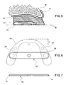
- the unit consisting of base 10, resin 30 and plate 20 ( figure 5 ) is then supplied to the dentist, who places it in the patient's oral cavity.
- the upper face 11 of the base featuring the impression of the edentulous arch, adapts perfectly to it, making contact with the mucosa M.
- the dentist can easily manipulate the resin and the plate with his fingers, by suitably squashing the resin, locally lifting up or lowering the plate 20 to adjust its height and inclination until the lower flat surface 21 is perfectly positioned and oriented according to certain morphological planes that will determine an ideal occlusion plane ⁇ for the prosthesis with respect to the bone structure of the patient.
- the blind holes 22 are used to determine a so-called occlusion key; the blind holes 22 create, by impression, a pair of corresponding projecting formations (not illustrated) in a strip of silicone or other malleable material applied on the jaw. Reference marks are thus obtained that will allow the dentist to manufacture a mandibular dental prosthesis that helps to define a correct occlusion with the maxillary one. Near to the blind holes 22 respective mutually facing recesses 28 are created that are used for supporting and maintaining the opposed ends 41 of a bar 40, illustrated in figures 6 and 7 , of the known type, used to determine the intermaxillary relationship on the horizontal plane defined as centric occlusion.
- the invention should not be considered to be limited to the embodiment described and illustrated here, which represents just one example embodiment of the plate, relative to the manufacture of a maxillary dental prosthesis.
- the materials selected for the plate, as well as its thickness and the width of the elliptical and parabolic arcs that define its edges can vary according to requirements.
- certain constructive details can also be modified.
- the point of the plate that defines the position of the interincisive papilla can be made to be defined by a portion having a different shape to the appendix indicated here with 25.
Landscapes
- Health & Medical Sciences (AREA)
- Oral & Maxillofacial Surgery (AREA)
- Dentistry (AREA)
- Epidemiology (AREA)
- Life Sciences & Earth Sciences (AREA)
- Animal Behavior & Ethology (AREA)
- General Health & Medical Sciences (AREA)
- Public Health (AREA)
- Veterinary Medicine (AREA)
- Dental Tools And Instruments Or Auxiliary Dental Instruments (AREA)
- Dental Preparations (AREA)
- Dental Prosthetics (AREA)
Claims (14)
- Plaquette incurvée (20) pour la fabrication d'une prothèse dentaire maxillaire, qui présente :une forme généralement en U, délimitée par deux contours sensiblement en forme de parabole, un bord externe (23) correspondant au contour des parois vestibulaires des incisives et des molaires de la prothèse à fabriquer, et un bord interne (24) correspondant au contour des parois linguales desdites dents,une surface plate (21) sur sa face inférieure,une partie (25) définissant un point de référence visible (26) correspondant à la position du tubercule palatin rétro-incisif (P),et dans laquelle la distance (d) entre le point de référence (26) et un point central (24a) du bord externe (23) qui indique une position située entre les parois les plus vestibulaires des incisives centrales supérieures, est comprise entre 8 et 10 mm.
- Plaquette selon la revendication 1, dans laquelle la partie qui définit la référence visible (26) est définie par le sommet d'un appendice (25), qui s'étend à partir du bord interne (24).
- Plaquette selon la revendication 2, dans laquelle l'appendice (25) fait saillie vers l'arrière à partir d'un segment avant du bord interne (24).
- Plaquette selon la revendication 1, dans laquelle la distance (d) est de 9 mm.
- Plaquette selon la revendication 1, dans laquelle le bord externe (23) présente un segment avant central en forme d'arc elliptique (23a), dans laquelle trois marques de référence sont mises en relief : une marque de référence centrale (24a) définissant la position du frein au niveau d'un point intermédiaire entre les surfaces vestibulaires des incisives centrales et deux marques de référence latérales (24b, 24c) dans les positions des axes de référence des canines droite et gauche.
- Plaquette selon la revendication 5, dans laquelle trois marques de référence (24a, 24b, 24c) sont formées comme des encoches évidées.
- Plaquette selon l'une quelconque des revendications précédentes, dans laquelle deux évidements verticaux (22), chacun positionné dans l'une des branches gauche et droite respectives de la plaquette, sont réalisés dans la surface plate inférieure (21).
- Plaquette selon la revendication 7, dans laquelle lesdits évidements verticaux (22) sont des trous borgnes.
- Plaquette selon l'une quelconque des revendications précédentes, qui présente au moins un trou de passage (27) qui s'ouvre sur la surface plate inférieure (21).
- Plaquette selon la revendication 7 ou 8, dans laquelle deux évidements (28), chacun positionné dans l'une des branches gauche et droite respectives de la plaquette, sont à proximité des évidements verticaux (22) réalisés dans la surface plate inférieure (21), lesquels évidements (28) sont utilisés pour supporter et maintenir les extrémités opposées (41) d'une barre (40).
- Plaquette selon la revendication 10, dans laquelle lesdits évidements (28) se font mutuellement face.
- Plaquette selon l'une quelconque des revendications précédentes, réalisée avec une matière plastique relativement rigide.
- Plaquette selon la revendication 12, réalisée à partir d'une résine acrylique.
- Procédé pour le positionnement et le modelage d'un matériau malléable pouvant temporairement supporter les molaires selon des positions et des orientations données, comprenant les étapes consistant à :prévoir une base de test (10) composée d'un corps rigide d'une épaisseur sensiblement uniforme qui présente sur sa face supérieure (11), l'empreinte de l'arc maxillaire édenté d'un patient ;prévoir une plaquette incurvée (20) selon l'une quelconque des revendications 1 à 13 ;détecter la position (P) du tubercule palatin rétro-incisif et le mettre en relief avec une marque de référence (P) sur la face inférieure (12) de la base (10) ;poser la plaquette (20) sur la face inférieure (12) de la base (10), faisant coïncider le point de référence visible (26) de la plaquette (20) avec la marque de référence de la position (P) du tubercule palatin rétro-incisif sur la base (10) ;orienter la plaquette (20) sur la base (10) afin d'aligner les branches gauche et droite de la plaquette incurvée (20) avec des reliefs respectifs de la base qui indiquent des segments correspondants de l'arc maxillaire édenté ;tracer sur la face inférieure (12) de la base (10) au moins une partie des bords interne et externe (23, 24) de la plaquette (20), afin de souligner sur la base (10), les bordures d'une zone incurvée (13) à l'intérieur de laquelle les incisives et les molaires seront ensuite positionnées ;appliquer sur la zone incurvée (13), une bande de matériau malléable (30) ;appliquer la plaquette (20) sous la bande de matériau malléable (30) afin de présenter la surface plate inférieure (21) sur la surface,placer l'unité composée de la base (10), avec la plaquette (20) et le matériau malléable (30) intercalé entre la base (10) et la plaquette (20) dans la bouche du patient, en posant la face supérieure (11) de la base (10) contre la muqueuse qui recouvre l'arc maxillaire édenté ;manipuler le matériau malléable (30) et/ou lever, abaisser ou incliner la plaquette (20) afin d'ajuster la hauteur et l'inclinaison de la face plate inférieure (21) selon un plan d'occlusion souhaité (π).
Applications Claiming Priority (1)
| Application Number | Priority Date | Filing Date | Title |
|---|---|---|---|
| ITTO2008A000780A IT1394129B1 (it) | 2008-10-23 | 2008-10-23 | Elemento a piastra per la fabbricazione di una protesi dentaria |
Publications (2)
| Publication Number | Publication Date |
|---|---|
| EP2179706A1 EP2179706A1 (fr) | 2010-04-28 |
| EP2179706B1 true EP2179706B1 (fr) | 2011-11-09 |
Family
ID=41119978
Family Applications (1)
| Application Number | Title | Priority Date | Filing Date |
|---|---|---|---|
| EP09173755A Not-in-force EP2179706B1 (fr) | 2008-10-23 | 2009-10-22 | Plaquette servant à la fabrication d'une prothèse dentaire |
Country Status (5)
| Country | Link |
|---|---|
| US (1) | US20100105007A1 (fr) |
| EP (1) | EP2179706B1 (fr) |
| AT (1) | ATE532479T1 (fr) |
| ES (1) | ES2374491T3 (fr) |
| IT (1) | IT1394129B1 (fr) |
Families Citing this family (2)
| Publication number | Priority date | Publication date | Assignee | Title |
|---|---|---|---|---|
| CN107088100B (zh) * | 2017-06-16 | 2022-04-15 | 温州医科大学附属口腔医院 | 一种多功能口腔模型测绘装置 |
| CN107115155B (zh) * | 2017-06-16 | 2022-07-15 | 温州医科大学附属口腔医院 | 一种精确描绘基骨弓线和牙弓曲线的方法 |
Family Cites Families (3)
| Publication number | Priority date | Publication date | Assignee | Title |
|---|---|---|---|---|
| US4906186A (en) * | 1988-10-31 | 1990-03-06 | France Jr Stanley L | Template for setting artificial teeth in a denture |
| FR2684541B1 (fr) * | 1991-12-05 | 1994-03-18 | Andre Cottard | Support de prothese dentaire. |
| DE4306147A1 (de) * | 1993-02-27 | 1994-09-01 | Hans Peter Nell | Vorrichtung zur Halterung |
-
2008
- 2008-10-23 IT ITTO2008A000780A patent/IT1394129B1/it active
-
2009
- 2009-10-22 EP EP09173755A patent/EP2179706B1/fr not_active Not-in-force
- 2009-10-22 AT AT09173755T patent/ATE532479T1/de active
- 2009-10-22 US US12/603,997 patent/US20100105007A1/en not_active Abandoned
- 2009-10-22 ES ES09173755T patent/ES2374491T3/es active Active
Also Published As
| Publication number | Publication date |
|---|---|
| ITTO20080780A1 (it) | 2010-04-24 |
| US20100105007A1 (en) | 2010-04-29 |
| EP2179706A1 (fr) | 2010-04-28 |
| ES2374491T3 (es) | 2012-02-17 |
| IT1394129B1 (it) | 2012-05-25 |
| ATE532479T1 (de) | 2011-11-15 |
Similar Documents
| Publication | Publication Date | Title |
|---|---|---|
| US12232929B2 (en) | Methods and devices for jaw repositioning | |
| US12521209B2 (en) | Methods of separating occlusal surfaces with repositioning jaw elements | |
| EP3791824B1 (fr) | Méthode pour présenter des éléments de repositionnement de mâchoire | |
| RU2510252C2 (ru) | Зубные протезы, зубные дуги и способы их изготовления | |
| US11284976B2 (en) | Artificial teeth set including mandibular coupled artificial teeth having an arch shape and maxillary coupled artificial teeth having an arch shape | |
| US10610336B2 (en) | Tray appliance system for making a dental prosthesis | |
| JP6959662B2 (ja) | 基準義歯用位置合せ冶具、義歯作製キット、及びこれらを用いる義歯作製方法 | |
| CN102648875B (zh) | 一种个性化舌侧矫治器制作方法及舌侧矫治器 | |
| JP2009106686A (ja) | 蝋義歯の製造方法、ならびにそれに用いる人工歯列用標準陰型および咬合嵌合位決定用陰型 | |
| US20140154644A1 (en) | Method and apparatus for preparing denture | |
| EP2179706B1 (fr) | Plaquette servant à la fabrication d'une prothèse dentaire | |
| JP2018196535A (ja) | 基準義歯床、基準義歯、部分床義歯作製キット及び部分床義歯作製方法 | |
| WO2017093864A1 (fr) | Appareils dentaires présentant des éléments de repositionnement de mâchoire | |
| JP2020069128A (ja) | 作業用模型における顎堤吸収している状態を見出す測定装置とその方法 | |
| JP4291799B2 (ja) | 人工歯配列装置 | |
| CN110575270A (zh) | 用于植牙和修复的综合矫正方法 | |
| JP2017046727A (ja) | 上顎基準義歯床及び上顎基準義歯並びに義歯作製キット及びこれを用いる義歯作製方法 |
Legal Events
| Date | Code | Title | Description |
|---|---|---|---|
| PUAI | Public reference made under article 153(3) epc to a published international application that has entered the european phase |
Free format text: ORIGINAL CODE: 0009012 |
|
| AK | Designated contracting states |
Kind code of ref document: A1 Designated state(s): AT BE BG CH CY CZ DE DK EE ES FI FR GB GR HR HU IE IS IT LI LT LU LV MC MK MT NL NO PL PT RO SE SI SK SM TR |
|
| AX | Request for extension of the european patent |
Extension state: AL BA RS |
|
| 17P | Request for examination filed |
Effective date: 20101020 |
|
| REG | Reference to a national code |
Ref country code: DE Ref legal event code: R079 Ref document number: 602009003578 Country of ref document: DE Free format text: PREVIOUS MAIN CLASS: A61C0013000000 Ipc: A61C0013010000 |
|
| GRAP | Despatch of communication of intention to grant a patent |
Free format text: ORIGINAL CODE: EPIDOSNIGR1 |
|
| RIC1 | Information provided on ipc code assigned before grant |
Ipc: A61C 13/01 20060101AFI20110426BHEP |
|
| GRAS | Grant fee paid |
Free format text: ORIGINAL CODE: EPIDOSNIGR3 |
|
| GRAA | (expected) grant |
Free format text: ORIGINAL CODE: 0009210 |
|
| AK | Designated contracting states |
Kind code of ref document: B1 Designated state(s): AT BE BG CH CY CZ DE DK EE ES FI FR GB GR HR HU IE IS IT LI LT LU LV MC MK MT NL NO PL PT RO SE SI SK SM TR |
|
| REG | Reference to a national code |
Ref country code: GB Ref legal event code: FG4D |
|
| REG | Reference to a national code |
Ref country code: CH Ref legal event code: EP Ref country code: CH Ref legal event code: NV Representative=s name: JACOBACCI & PARTNERS S.P.A. |
|
| REG | Reference to a national code |
Ref country code: IE Ref legal event code: FG4D |
|
| REG | Reference to a national code |
Ref country code: DE Ref legal event code: R096 Ref document number: 602009003578 Country of ref document: DE Effective date: 20120119 |
|
| REG | Reference to a national code |
Ref country code: ES Ref legal event code: FG2A Ref document number: 2374491 Country of ref document: ES Kind code of ref document: T3 Effective date: 20120217 |
|
| REG | Reference to a national code |
Ref country code: NL Ref legal event code: VDEP Effective date: 20111109 |
|
| LTIE | Lt: invalidation of european patent or patent extension |
Effective date: 20111109 |
|
| PG25 | Lapsed in a contracting state [announced via postgrant information from national office to epo] |
Ref country code: IS Free format text: LAPSE BECAUSE OF FAILURE TO SUBMIT A TRANSLATION OF THE DESCRIPTION OR TO PAY THE FEE WITHIN THE PRESCRIBED TIME-LIMIT Effective date: 20120309 Ref country code: NO Free format text: LAPSE BECAUSE OF FAILURE TO SUBMIT A TRANSLATION OF THE DESCRIPTION OR TO PAY THE FEE WITHIN THE PRESCRIBED TIME-LIMIT Effective date: 20120209 Ref country code: LT Free format text: LAPSE BECAUSE OF FAILURE TO SUBMIT A TRANSLATION OF THE DESCRIPTION OR TO PAY THE FEE WITHIN THE PRESCRIBED TIME-LIMIT Effective date: 20111109 |
|
| PG25 | Lapsed in a contracting state [announced via postgrant information from national office to epo] |
Ref country code: GR Free format text: LAPSE BECAUSE OF FAILURE TO SUBMIT A TRANSLATION OF THE DESCRIPTION OR TO PAY THE FEE WITHIN THE PRESCRIBED TIME-LIMIT Effective date: 20120210 Ref country code: NL Free format text: LAPSE BECAUSE OF FAILURE TO SUBMIT A TRANSLATION OF THE DESCRIPTION OR TO PAY THE FEE WITHIN THE PRESCRIBED TIME-LIMIT Effective date: 20111109 Ref country code: BE Free format text: LAPSE BECAUSE OF FAILURE TO SUBMIT A TRANSLATION OF THE DESCRIPTION OR TO PAY THE FEE WITHIN THE PRESCRIBED TIME-LIMIT Effective date: 20111109 Ref country code: HR Free format text: LAPSE BECAUSE OF FAILURE TO SUBMIT A TRANSLATION OF THE DESCRIPTION OR TO PAY THE FEE WITHIN THE PRESCRIBED TIME-LIMIT Effective date: 20111109 Ref country code: SE Free format text: LAPSE BECAUSE OF FAILURE TO SUBMIT A TRANSLATION OF THE DESCRIPTION OR TO PAY THE FEE WITHIN THE PRESCRIBED TIME-LIMIT Effective date: 20111109 Ref country code: LV Free format text: LAPSE BECAUSE OF FAILURE TO SUBMIT A TRANSLATION OF THE DESCRIPTION OR TO PAY THE FEE WITHIN THE PRESCRIBED TIME-LIMIT Effective date: 20111109 Ref country code: PT Free format text: LAPSE BECAUSE OF FAILURE TO SUBMIT A TRANSLATION OF THE DESCRIPTION OR TO PAY THE FEE WITHIN THE PRESCRIBED TIME-LIMIT Effective date: 20120309 Ref country code: SI Free format text: LAPSE BECAUSE OF FAILURE TO SUBMIT A TRANSLATION OF THE DESCRIPTION OR TO PAY THE FEE WITHIN THE PRESCRIBED TIME-LIMIT Effective date: 20111109 Ref country code: PL Free format text: LAPSE BECAUSE OF FAILURE TO SUBMIT A TRANSLATION OF THE DESCRIPTION OR TO PAY THE FEE WITHIN THE PRESCRIBED TIME-LIMIT Effective date: 20111109 |
|
| PG25 | Lapsed in a contracting state [announced via postgrant information from national office to epo] |
Ref country code: CY Free format text: LAPSE BECAUSE OF FAILURE TO SUBMIT A TRANSLATION OF THE DESCRIPTION OR TO PAY THE FEE WITHIN THE PRESCRIBED TIME-LIMIT Effective date: 20111109 |
|
| PG25 | Lapsed in a contracting state [announced via postgrant information from national office to epo] |
Ref country code: BG Free format text: LAPSE BECAUSE OF FAILURE TO SUBMIT A TRANSLATION OF THE DESCRIPTION OR TO PAY THE FEE WITHIN THE PRESCRIBED TIME-LIMIT Effective date: 20120209 Ref country code: SK Free format text: LAPSE BECAUSE OF FAILURE TO SUBMIT A TRANSLATION OF THE DESCRIPTION OR TO PAY THE FEE WITHIN THE PRESCRIBED TIME-LIMIT Effective date: 20111109 Ref country code: DK Free format text: LAPSE BECAUSE OF FAILURE TO SUBMIT A TRANSLATION OF THE DESCRIPTION OR TO PAY THE FEE WITHIN THE PRESCRIBED TIME-LIMIT Effective date: 20111109 Ref country code: EE Free format text: LAPSE BECAUSE OF FAILURE TO SUBMIT A TRANSLATION OF THE DESCRIPTION OR TO PAY THE FEE WITHIN THE PRESCRIBED TIME-LIMIT Effective date: 20111109 |
|
| PG25 | Lapsed in a contracting state [announced via postgrant information from national office to epo] |
Ref country code: RO Free format text: LAPSE BECAUSE OF FAILURE TO SUBMIT A TRANSLATION OF THE DESCRIPTION OR TO PAY THE FEE WITHIN THE PRESCRIBED TIME-LIMIT Effective date: 20111109 |
|
| PLBE | No opposition filed within time limit |
Free format text: ORIGINAL CODE: 0009261 |
|
| STAA | Information on the status of an ep patent application or granted ep patent |
Free format text: STATUS: NO OPPOSITION FILED WITHIN TIME LIMIT |
|
| PGFP | Annual fee paid to national office [announced via postgrant information from national office to epo] |
Ref country code: IT Payment date: 20120630 Year of fee payment: 4 |
|
| 26N | No opposition filed |
Effective date: 20120810 |
|
| REG | Reference to a national code |
Ref country code: DE Ref legal event code: R097 Ref document number: 602009003578 Country of ref document: DE Effective date: 20120810 |
|
| PG25 | Lapsed in a contracting state [announced via postgrant information from national office to epo] |
Ref country code: MC Free format text: LAPSE BECAUSE OF NON-PAYMENT OF DUE FEES Effective date: 20121031 |
|
| PG25 | Lapsed in a contracting state [announced via postgrant information from national office to epo] |
Ref country code: FI Free format text: LAPSE BECAUSE OF FAILURE TO SUBMIT A TRANSLATION OF THE DESCRIPTION OR TO PAY THE FEE WITHIN THE PRESCRIBED TIME-LIMIT Effective date: 20111109 |
|
| REG | Reference to a national code |
Ref country code: IE Ref legal event code: MM4A |
|
| REG | Reference to a national code |
Ref country code: FR Ref legal event code: ST Effective date: 20130628 |
|
| PG25 | Lapsed in a contracting state [announced via postgrant information from national office to epo] |
Ref country code: CZ Free format text: LAPSE BECAUSE OF NON-PAYMENT OF DUE FEES Effective date: 20121022 Ref country code: IE Free format text: LAPSE BECAUSE OF NON-PAYMENT OF DUE FEES Effective date: 20121022 Ref country code: DE Free format text: LAPSE BECAUSE OF NON-PAYMENT OF DUE FEES Effective date: 20130501 |
|
| REG | Reference to a national code |
Ref country code: DE Ref legal event code: R119 Ref document number: 602009003578 Country of ref document: DE Effective date: 20130501 |
|
| PG25 | Lapsed in a contracting state [announced via postgrant information from national office to epo] |
Ref country code: FR Free format text: LAPSE BECAUSE OF NON-PAYMENT OF DUE FEES Effective date: 20121031 |
|
| PG25 | Lapsed in a contracting state [announced via postgrant information from national office to epo] |
Ref country code: MT Free format text: LAPSE BECAUSE OF FAILURE TO SUBMIT A TRANSLATION OF THE DESCRIPTION OR TO PAY THE FEE WITHIN THE PRESCRIBED TIME-LIMIT Effective date: 20111109 |
|
| REG | Reference to a national code |
Ref country code: ES Ref legal event code: FD2A Effective date: 20140408 |
|
| PG25 | Lapsed in a contracting state [announced via postgrant information from national office to epo] |
Ref country code: TR Free format text: LAPSE BECAUSE OF FAILURE TO SUBMIT A TRANSLATION OF THE DESCRIPTION OR TO PAY THE FEE WITHIN THE PRESCRIBED TIME-LIMIT Effective date: 20111109 |
|
| PG25 | Lapsed in a contracting state [announced via postgrant information from national office to epo] |
Ref country code: LU Free format text: LAPSE BECAUSE OF NON-PAYMENT OF DUE FEES Effective date: 20121022 Ref country code: SM Free format text: LAPSE BECAUSE OF FAILURE TO SUBMIT A TRANSLATION OF THE DESCRIPTION OR TO PAY THE FEE WITHIN THE PRESCRIBED TIME-LIMIT Effective date: 20111109 Ref country code: ES Free format text: LAPSE BECAUSE OF NON-PAYMENT OF DUE FEES Effective date: 20121023 |
|
| REG | Reference to a national code |
Ref country code: CH Ref legal event code: PL |
|
| GBPC | Gb: european patent ceased through non-payment of renewal fee |
Effective date: 20131022 |
|
| PG25 | Lapsed in a contracting state [announced via postgrant information from national office to epo] |
Ref country code: GB Free format text: LAPSE BECAUSE OF NON-PAYMENT OF DUE FEES Effective date: 20131022 Ref country code: HU Free format text: LAPSE BECAUSE OF FAILURE TO SUBMIT A TRANSLATION OF THE DESCRIPTION OR TO PAY THE FEE WITHIN THE PRESCRIBED TIME-LIMIT Effective date: 20091022 Ref country code: LI Free format text: LAPSE BECAUSE OF NON-PAYMENT OF DUE FEES Effective date: 20131031 Ref country code: CH Free format text: LAPSE BECAUSE OF NON-PAYMENT OF DUE FEES Effective date: 20131031 |
|
| PG25 | Lapsed in a contracting state [announced via postgrant information from national office to epo] |
Ref country code: IT Free format text: LAPSE BECAUSE OF NON-PAYMENT OF DUE FEES Effective date: 20131022 |
|
| PG25 | Lapsed in a contracting state [announced via postgrant information from national office to epo] |
Ref country code: MK Free format text: LAPSE BECAUSE OF FAILURE TO SUBMIT A TRANSLATION OF THE DESCRIPTION OR TO PAY THE FEE WITHIN THE PRESCRIBED TIME-LIMIT Effective date: 20111109 |
|
| REG | Reference to a national code |
Ref country code: AT Ref legal event code: MM01 Ref document number: 532479 Country of ref document: AT Kind code of ref document: T Effective date: 20141022 |
|
| PG25 | Lapsed in a contracting state [announced via postgrant information from national office to epo] |
Ref country code: AT Free format text: LAPSE BECAUSE OF NON-PAYMENT OF DUE FEES Effective date: 20141022 |