EP2180068B1 - Vorrichtung zur Behandlung von Schlacke - Google Patents
Vorrichtung zur Behandlung von Schlacke Download PDFInfo
- Publication number
- EP2180068B1 EP2180068B1 EP20100152190 EP10152190A EP2180068B1 EP 2180068 B1 EP2180068 B1 EP 2180068B1 EP 20100152190 EP20100152190 EP 20100152190 EP 10152190 A EP10152190 A EP 10152190A EP 2180068 B1 EP2180068 B1 EP 2180068B1
- Authority
- EP
- European Patent Office
- Prior art keywords
- barrel body
- sending
- treatment equipment
- outer barrel
- steel slag
- Prior art date
- Legal status (The legal status is an assumption and is not a legal conclusion. Google has not performed a legal analysis and makes no representation as to the accuracy of the status listed.)
- Expired - Lifetime
Links
Images





Classifications
-
- C—CHEMISTRY; METALLURGY
- C21—METALLURGY OF IRON
- C21B—MANUFACTURE OF IRON OR STEEL
- C21B3/00—General features in the manufacture of pig-iron
- C21B3/04—Recovery of by-products, e.g. slag
- C21B3/06—Treatment of liquid slag
-
- B—PERFORMING OPERATIONS; TRANSPORTING
- B02—CRUSHING, PULVERISING, OR DISINTEGRATING; PREPARATORY TREATMENT OF GRAIN FOR MILLING
- B02C—CRUSHING, PULVERISING, OR DISINTEGRATING IN GENERAL; MILLING GRAIN
- B02C17/00—Disintegrating by tumbling mills, i.e. mills having a container charged with the material to be disintegrated with or without special disintegrating members such as pebbles or balls
- B02C17/04—Disintegrating by tumbling mills, i.e. mills having a container charged with the material to be disintegrated with or without special disintegrating members such as pebbles or balls with unperforated container
- B02C17/06—Disintegrating by tumbling mills, i.e. mills having a container charged with the material to be disintegrated with or without special disintegrating members such as pebbles or balls with unperforated container with several compartments
-
- B—PERFORMING OPERATIONS; TRANSPORTING
- B02—CRUSHING, PULVERISING, OR DISINTEGRATING; PREPARATORY TREATMENT OF GRAIN FOR MILLING
- B02C—CRUSHING, PULVERISING, OR DISINTEGRATING IN GENERAL; MILLING GRAIN
- B02C17/00—Disintegrating by tumbling mills, i.e. mills having a container charged with the material to be disintegrated with or without special disintegrating members such as pebbles or balls
- B02C17/18—Details
- B02C17/181—Bearings specially adapted for tumbling mills
-
- B—PERFORMING OPERATIONS; TRANSPORTING
- B02—CRUSHING, PULVERISING, OR DISINTEGRATING; PREPARATORY TREATMENT OF GRAIN FOR MILLING
- B02C—CRUSHING, PULVERISING, OR DISINTEGRATING IN GENERAL; MILLING GRAIN
- B02C17/00—Disintegrating by tumbling mills, i.e. mills having a container charged with the material to be disintegrated with or without special disintegrating members such as pebbles or balls
- B02C17/18—Details
- B02C17/183—Feeding or discharging devices
-
- B—PERFORMING OPERATIONS; TRANSPORTING
- B02—CRUSHING, PULVERISING, OR DISINTEGRATING; PREPARATORY TREATMENT OF GRAIN FOR MILLING
- B02C—CRUSHING, PULVERISING, OR DISINTEGRATING IN GENERAL; MILLING GRAIN
- B02C17/00—Disintegrating by tumbling mills, i.e. mills having a container charged with the material to be disintegrated with or without special disintegrating members such as pebbles or balls
- B02C17/18—Details
- B02C17/24—Driving mechanisms
-
- C—CHEMISTRY; METALLURGY
- C21—METALLURGY OF IRON
- C21B—MANUFACTURE OF IRON OR STEEL
- C21B7/00—Blast furnaces
- C21B7/14—Discharging devices, e.g. for slag
-
- C—CHEMISTRY; METALLURGY
- C21—METALLURGY OF IRON
- C21B—MANUFACTURE OF IRON OR STEEL
- C21B2400/00—Treatment of slags originating from iron or steel processes
- C21B2400/02—Physical or chemical treatment of slags
- C21B2400/022—Methods of cooling or quenching molten slag
- C21B2400/024—Methods of cooling or quenching molten slag with the direct use of steam or liquid coolants, e.g. water
-
- C—CHEMISTRY; METALLURGY
- C21—METALLURGY OF IRON
- C21B—MANUFACTURE OF IRON OR STEEL
- C21B2400/00—Treatment of slags originating from iron or steel processes
- C21B2400/02—Physical or chemical treatment of slags
- C21B2400/022—Methods of cooling or quenching molten slag
- C21B2400/026—Methods of cooling or quenching molten slag using air, inert gases or removable conductive bodies
-
- C—CHEMISTRY; METALLURGY
- C21—METALLURGY OF IRON
- C21B—MANUFACTURE OF IRON OR STEEL
- C21B2400/00—Treatment of slags originating from iron or steel processes
- C21B2400/05—Apparatus features
- C21B2400/052—Apparatus features including rotating parts
-
- C—CHEMISTRY; METALLURGY
- C21—METALLURGY OF IRON
- C21B—MANUFACTURE OF IRON OR STEEL
- C21B2400/00—Treatment of slags originating from iron or steel processes
- C21B2400/05—Apparatus features
- C21B2400/052—Apparatus features including rotating parts
- C21B2400/056—Drums whereby slag is poured on or in between
-
- C—CHEMISTRY; METALLURGY
- C21—METALLURGY OF IRON
- C21B—MANUFACTURE OF IRON OR STEEL
- C21B2400/00—Treatment of slags originating from iron or steel processes
- C21B2400/05—Apparatus features
- C21B2400/064—Thermally-conductive removable bodies, e.g. balls
-
- Y—GENERAL TAGGING OF NEW TECHNOLOGICAL DEVELOPMENTS; GENERAL TAGGING OF CROSS-SECTIONAL TECHNOLOGIES SPANNING OVER SEVERAL SECTIONS OF THE IPC; TECHNICAL SUBJECTS COVERED BY FORMER USPC CROSS-REFERENCE ART COLLECTIONS [XRACs] AND DIGESTS
- Y02—TECHNOLOGIES OR APPLICATIONS FOR MITIGATION OR ADAPTATION AGAINST CLIMATE CHANGE
- Y02W—CLIMATE CHANGE MITIGATION TECHNOLOGIES RELATED TO WASTEWATER TREATMENT OR WASTE MANAGEMENT
- Y02W30/00—Technologies for solid waste management
- Y02W30/50—Reuse, recycling or recovery technologies
Definitions
- This invention relates to an equipment for treating metallurgical molten slag in hot state.
- the existing metallurgical slag treatment equipment by barrel method is one of currently advanced slag treatment equipments. It has advantages of short flow path, less investment, safety, reliability and low energy consumption, the slag, after having been treated, can be utilized directly, and the pollution is low.
- the metallurgical slag treatment technology and equipment by barrel method in particular, a vertical feed double cavity barrel equipment can overcome the inadequacy of traditional slag treatment process and equipments, it has the advantages of short flow path, less investment, convenient operation, low energy consumption and good quality of treated product slag.
- a prior art patent CN 1141401 C discloses "A Steel Slag Treatment Equipment by Double Cavity Barrel method" for treating steel slag.
- the equipment has two oppositely open squirrel-cage type barrel bodies consisting of backing rings 16, grid sections 31 and rotary end covers, wherein the grid sections and backing rings are connected together with bolts.
- a flow branching pan 9 capable of synchronously rotating, which divides the two barrel bodies into two relatively independent cavity bodies.
- the force moment causing the rotation of flow branching pans comes from a mandrel 6,
- the lower part of flow branching pan is a stationery retaining ring 12 of semi-ring shape having the function of separating the two cavity body and preventing the leakage of slag material 7 and cooling media 8.
- Below the barrel body is a discharge funnel 13 for discharging pulverized slag.
- a fixed hood 14 having a sealing function is located outside the rotary barrel body.
- steel slag is fed into funnel 1, falls onto the flow branching pan 9, and is guided respectively into two barrel bodies, after being cooled and crushed, by cooling body 8 (steel balls) leaks out through the slits between the grid sections, and is discharged out of the equipment through discharge funnel 13.
- the vapor generated in the process is collected by the fixed hood and discharged through specially provided shell and flue.
- the equipment uses vertical slag feeding, thus solving the problem of feeding slag of high viscosity relatively perfectly.
- the barrel is a single layer barrel body construction, thus the cooling of slag material is not sufficient and red slag tends to appear; there are relatively too many supporting devices and the equipment is heavy; its lower space is limited, thus maintenance and repair are inconvenient.
- the retaining ring is located at the lower part of the rotating flow branching pan within the barrel body.
- the retaining ring comprises a base plate and side plates on which there are many concave pits.
- the base plate and side plates form a V-shaped cell, in which slag material and many steel balls are filled. Through the base plate there is drilled a discharge hole.
- the existing metallurgical slag treatment equipment by barrel method uses a barrel body in the shape of a circular table, its cone portion is outside an inner barrel body and on its cylindrical portion there are many sending plates uniformly distributed peripherally.
- the sending plates have an inclination angle ⁇ with respect to the radial direction.
- the slag material after being treated in the inner barrel body falls by gravity to the inside of the conical surface of the outer barrel body and is guided on the inclined surface of the conical body into the cylindrical barrel portion, and under the action of sending plates is sent into a discharge chute and through it out of the equipment.
- This barrel body suffers the disadvantages that it must have a conical shape of inclination angle ⁇ in order to discharge slag material, the value of ⁇ being equal to the rest (repose) angle of slag material, generally 45 °. In this way the slag material corning down from the inner barrel body can be sent axially to the lower part of the discharge chute.
- the diameter of the outer barrel body equals to the diameter of the inner barrel body plus twice the process width of inner barrel body, as a result, the outer diameter of barrel body is very large, the weight is large and investment is high.
- the process of the existing metallurgical slag treatment by barrel method is such, through a slag feed inlet slag material enters the rotating inner barrel body, which is a squirrel-cage shape barrel body formed by many grid sections, at two ends of which are two end covers, under the inertia the slag material is thrown onto the surface of cooling media (steel balls), then penetrates by gravity into the slits between steel balls to be cooled and crushed, discharged through the grid sections at the bottom of inner barrel body into the outer barrel body.
- a slag feed inlet slag material enters the rotating inner barrel body, which is a squirrel-cage shape barrel body formed by many grid sections, at two ends of which are two end covers, under the inertia the slag material is thrown onto the surface of cooling media (steel balls), then penetrates by gravity into the slits between steel balls to be cooled and crushed, discharged through the grid sections at the bottom of inner barrel body into the outer barrel body.
- cooling media
- the temperature of steel balls in this region increases rapidly and can not be cooled timely, that is, loses the normal effect of heat transfer especially when the viscosity of hot slag material is high and thus the ability of slag material to penetrate into the slits between steel balls is weak, a large part of slag material will cover the upper surface of steel balls region of kidney shape and form " slag crust", where the contact area between slag material and steel balls is small, the steel balls taking part in cooling the slag material are those steel balls at the upper surface layer of balls in the kidney-shaped region, and, therefore, their cooling effect is low, tending to give rise to bursting in the barrel body, and the pulverizing effect is bad, tending to result in the discharge of red slag out of the equipment, not only affecting the service life of subsequent equipments, but also yielding product slag of low performance negating its direct utilization.
- the Patent Specification GB 296 682 describes a combined construction of a ball mill and a fan.
- the ball mill and the fan are built together, a perforated screen being arranged between them and both are mounted on hollow end bearings.
- Solid fuel is supplied through one of the bearings in conjunction with air induced by the fan.
- the pulverized particles mixed with air are forced by the fan through the other hollow end bearing.
- the mill may comprise two compartments.
- the object of the invention is to provide a double cavity type steel slag treatment equipment by barrel method with mandrel support to reduce weight and cost of equipment and at the same time to increase the space for maintenance and repair of the lower part.
- a further object of the invention is to provide a double cavity type steel slag treatment equipment by barrel method with mandrel support which can increase the cooling time of slag material in the equipment and thus improve the cooling effect, resulting in improving the product slag performance.
- Another object of the invention is to provide a retaining ring for a double cavity type steel slag treatment equipment by barrel method.
- the retaining ring overcomes the drawback that the existing retaining ring construction affects the rotation of barrel body, while the side plates of the retaining ring of the invention have smooth surface offering less frictional resistance to the motion of cooling media and slag material and thus less affecting the rotation of barrel body.
- the service life of the retaining ring of the invention is long, and the construction of the retaining ring is simple and its cost is low.
- Still another object of the invention is to provide a barrel body for the rotation of barrel body, which overcomes the drawback that the existing barrel is large and its investment is high.
- the barrel body of the invention employs spiral sending plates, making the barrel body have the ability of transporting slag material in axial direction, decreasing the diameter of the barrel body, and reducing the equipment in vestment.
- Still another object of the invention is to provide sending hands for a double cavity metallurgical slag treatment equipment by barrel method, which overcomes the drawback that the contact between the highly viscous molten slag and steel balls in existing inner barrel body is small, causing the molten slag in the barrel body of the invention to be sufficiently cooled and crushed.
- a double cavity metallurgical slag treatment equipment by barrel method with a mandrel support comprising left and right barrel bodies, flow branching pans, a mandrel and a feed funnel, wherein the pan is disposed between the left and right barrel bodies and opposed to the flow branching pan are the opening parts of the left and right barrel bodies; over the flow branching pans is disposed a feed funnel, while below the flow branching pan is disposed a retaining ring; the mandrel fixedly connects the left and right barrel bodies and the flow branching pans, wherein, outside the left and right barrel bodies at both ends of the mandrel supporting bearings are mounted.
- the left and right barrel bodies have two portions, namely inner and outer portions.
- the inner barrel body consists of grid section, one end of grid section is fixed to the end cover of outer barrel body through the insertion opening formed by supporting rings, the other end of the grid section is joined with the supporting rings on the outer barrel body.
- the mandrel fixedly connects the outer barrel body. Outside the outer barrel body are mounted geared rings for transmitting force moment, the geared rings are fixedly connected with one end of the outer barrel body.
- spiral sending plates which are fixed on the inner surface of outer barrel body.
- the axis of the spiral sending plates forms a certain definite angle (30°-55°) with the axis of the outer barrel body.
- the said retaining ring has supporting ribbed plates radially arranged between the side plates of the left and right barrel bodies.
- this invention adds supporting bearings at two ends of the mandrel while maintaining double barrel bodies and vertical feed, the weight of equipment is shared equally by two bearing seats. Further, thus invention eliminates the use of supporting rollers and backing rings, greatly decreasing the weight and manufacturing cost of the equipment, and simplifies the lower construction, giving a large space for maintenance and repair. The whole construction of equipment is compact Because of the use of mandrel support, the bearings can accomplish good axial orientation, solving the problem of axial scurry which troubles the barrel equipment.
- an outer barrel body capable of synchronously rotating is added, and within the outer barrel body are provided spiral sending plates, the axis of which forms a certain definite angle with the axis of the barrel.
- the spiral sending plates causes a certain definite quantity of water to be present in the outer barrel body, intensifying the cooling effect of the outer barrel body. This increases the cooling time of slag material in the barrel body and ensures that the product slag be discharged at the set regions.
- the mother board at the lower part of the retaining ring is eliminated and the left and right side plates are supported by ribbed plates of radial shape, causing all the slag material that can enter the clearance between the retaining ring and flow branching pan to be rapidly and smoothly discharged, meanwhile effectively reducing the weight of equipment, the upper part of discharge funnel is fixedly connected with the fixed hood, its lower part is connected with the inlet of a slag material transport device.
- the invention can effectively ensure that the metallurgical slag of various states (liquid state, glass state, even solid state less 300 mm in size can smoothly enter the equipment; the slag material is cooled sufficiently, and the performance of product slag is stable, the weight of equipment is small and its cost is low; the space available for maintenance and repair is large.
- a retaining ring for the double cavity type metallurgical slag treatment equipment by barrel method comprising a base plate, side plates and ribbed plates, the base plate being a circular strip plate for the most part, side plates being annular plates.
- the arrangement of side plates and the base plate is shaped, two side plates are mounted in parallel on the base plate at an inward distance from the side surface of the base plate, the distance being equal to the width of the base plate itself.
- a ribbed plate At the inside of the side plate.
- the inward distance at which the side plate is mounted on the base plate is 50-150 cm; the mounting position of side plate is semi-ring in shape, high at the rear and low at the front.
- the surface of the side plates of the invention is smooth, and the side plate is mounted at an inward distance from the side face of the base plate, this inward distance from the side face of the base plate is just for the cooling media (steel balls) to stick to the side plate, being motionless or slightly moving during rotation of the barrel body, and thus accomplishing the object that the side plate is less worn out and at the same time the rotation of barrel body is less affected.
- the retaining ring is of a semicircular ring construction and has a certain clearance with both the barrel body and the flow branching pan, in this way, playing a role of closing the slag material and process media and protecting the flow branching pan to prevent the direct wear of the surface of the flow branching pan by the action of the slag material and process media.
- This invention has features of long service life, low resistance to the rotation of barrel body, simple constriction and low cost.
- a barrel body for a metallurgical slag treatment equipment by barrel method within the barrel body is disposed an inner barrel body, on the inner surface of the barrel body there are spiral sending plates uniformly distributed along the inner surface of the barrel.
- the above-mentioned metallurgical slag treatment equipment uses a barrel body.
- the said sending plates have planar or spiral shaped surface.
- the barrel body of the invention employs spiral sending plates in place of the conical face of the original barrel body, while securing normal discharge, it simplifies the circular table type barrel body, decreasing the diameter of barrel body, optimizing the equipment construction, reducing the weight of the equipment.
- the construction is simple and the manufacturing cost of the equipment is reduced.
- convex sending hands on the inner wall of the inner barrel body of the inner barrel there are mounted convex sending hands.
- sending hands on the grid sections of the inner barrel there are sending hands, the cross-section of which being L-shaped or inverted II-shaped.
- the steel balls can fall down from the L-shaped or inverted II-shaped sending hands.
- sending hands at the end of which is mounted a guide plate.
- the sending hands are radially arranged about the center of the end cover.
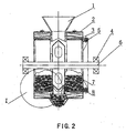
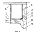
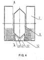
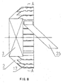
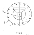
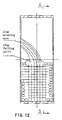
- a steel slag treatment equipment be barrel method comprising left and right barrel bodies 2, flow branching pan 9, mandrel 6, feed funnel 1; the left and right barrel bodies have two layers (inner and outer barrel bodies); the left and right outer barrel bodies 2 are respectively connected to mandrel 6; inner barrel body is composed of grid sections 31, one end of which is fixed on the end cover of outer barrel body 2 through the insertion opening formed by supporting rings 18,19, the other end of grid section 31 is joined with the supporting ring 11 fixed on outer barrel body 2 via a fastener 10. Between inner barrel body 3 and outer barrel body 2 are mounted sending plates 17 fixed on the inner surface of outer barrel body 2.
- the axis of sending plates 17 form an angle (35° - 55°) with the axis of outer barrel body.
- a flow branching pan 9 fixedly connected to mandrel 6.
- Mandrel 6 is supported by bearings 4 located at outer sides of the left and right barrel bodies.
- a driving geared ring 5 is fixedly connected, which is located at the outer side of the outer barrel body 2.
- a retaining ring 12 which forms a gap fit respectively with flow branching pan 9 and inner barrel body 3.
- Retaining ring 12 has supporting ribbed plates radially disposed between two side plates of left and right barrel bodies.
- the lower pant of retaining ring 12 is empty.
- Retaining ring 12 is directly fixed on the foundation.
- a fixed hood 14 which forms a gap fit with outer barrel body 2.
- the fixed hood 14 is used for collecting the slag material and vapor discharged from outer barrel body 2. Fixed hood 14 is also fixed on the foundation. Above flow branching pan 9 is a feed funnel 1, which forms a gap fit with flow branching pan 9 and is directly fixed on the foundation. The upper part of discharge funnel 13 is fixedly connected with fixed hood 14, while its lower part is connected with the inlet of a slag material transport device.
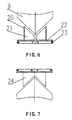
- a retaining ring 12 for the double cavity type metallurgical slag treatment equipment by barrel method It comprises base plate 22, side plate 20, cover plate 24 and ribbed plate.
- the base plate 22 is of a frame construction covered with circular shaped slat for the most part to secure the rigidity of retaining ring 12; on two sides of base plate 22 are covered with backing (lining) boards 23 connected with base plate 22 by means of bolts for easy assembling and disassembling, on base plate there is a discharge hole for timely discharge of a small amount of slag material carried down from flow branching pan 9 out of retaining ring 12.
- Side plate 20 is an annular plate.
- Two side plates 20 are mounted in parallel on base plate 22 at an inward distance from the side surface of base plate 22, the distance being 50-150cm, preferably 80-90cm, in this way, the cooling media sticking (following closely) to side plate 20 are motionless or move slightly forming a relatively turbulent self-grinding layer of media playing the role of protecting the side plate 20 of retaining ring.
- Inside the side plate 20 is disposed ribbed plate 21 for supporting the side plate 20; at two ends of side plate 20 are mounted cover plates 24 to prevent slag material from falling into retaining ring 12.
- base plate 22, side plate 20, ribbed plate 21 and cover plate 24 form a semi-hermetic construction separating left and right barrel bodies. Both the surface of base plate and side plate in contact with process media have dismountable lining boards.
- the mounting position of side plate 20 is semi-ring in shape, high at the rear and low at the front because the rotating direction of barrel body 2 is from the front to the rear, thus more effectively using the retaining ring 12.
- Outer barrel body 2 is regularly cylindrically shaped.
- the sending plate 17 not only has an inclination angle ⁇ with respect to the radial direction of outer barrel body 2, but also has an inclination angle ⁇ with respect to the axial direction.
- Sending plates may be planer or spiral.
- Within outer barrel body 2 is mounted an inner barrel body 3.
- On outer barrel 2 is mounted a discharge chute 25.
- Slag material treated in inner barrel body 3 falls in side of the outer barrel body 2 by gravity and following the rotation of the outer barrel body 2, the slag material is subjected to an downward force component at angle ⁇ along sending plate 17 under the action of gravity, and slag material automatically slides along axial direction under the action of the force component; sliding from the vertical projection area of inner barrel body 3 onto the projection area of discharge chute 25 and out of the equipment.
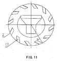
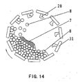
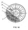
- convex sending hands 28 on the inner wall of inner barrel body 3.
- the sending hands scoop up steel balls 8 and slag material 7 in inner barrel body 3 and throw them down on the steel balls 8 and slag material 7 at the lower part of inner barrel body 3 after inner barrel body 3 has rotated a certain definite angle. Slag materials 7 are struck and crushed, and the steel balls 8 and slag materials near the surface of inner barrel body 3 are contiguously scooped up by sending hands 28, improving the stirring and mixing of the steel balis 8 and slag material 7.
- sending hand 17 there is shown an embodiment of sending hand 17. That is , on grid sections 31 of inner barrel body 3 are mounted sending hands 28, the cross-section of which is L-shaped.
- the L-shaped sending hands 28 can guide steel balls 8 to fall accurately into the region where steel balls 8 should fall into, generally the slag falling point of slag material 7.
- the steel balls8 fallen down strike and crush slag material and intensity cooling effect.
- sending hands 28 also scoop up the steel balls 8 and slag material 7 near grid sections 31 of inner barrel body, improving the stirring and mixing of steel balls 8 and slag material 7 and facilitating the heat exchange of steel balls 8 and slag material 7.
- Sending hands may be castings or weldments and are convenient for change.
- Sending hands 28 are uniformly radially arranged from the center of end cover 26.
- Working face of sending hands 28 is flat.
- Guide plate 17 is V-shaped, the magnitude of sloping of the V-shape is appropriate for steel balls 8 to be thrown just to the slag falling point of slag material 7.
- Sending hands 28 and guide planes 27 may be castings or weldments and are convenient for change.
Landscapes
- Engineering & Computer Science (AREA)
- Food Science & Technology (AREA)
- Chemical & Material Sciences (AREA)
- Manufacturing & Machinery (AREA)
- Materials Engineering (AREA)
- Metallurgy (AREA)
- Organic Chemistry (AREA)
- Carbon Steel Or Casting Steel Manufacturing (AREA)
- Furnace Details (AREA)
- Treatment Of Steel In Its Molten State (AREA)
Claims (8)
- Stahlschlackenbehandlungsvorrichtung, umfassend linke und rechte Zylinderkörper (2, 3), eine Stromverteilerpfanne (9), eine Spindel (6), einen Spindelbeschickungstrichter (1), wobei zwischen dem linken und rechten Zylinderkörper (2,3) eine Stromverteilerpfanne (9) angeordnet ist, der das offene Ende des Zylinderkörpers (2, 3) gegenüber liegt, über der Stromverteilerpfanne (9) ein Beschickungstrichter (1) montiert ist, unter der Stromverteilerpfanne (9) ein Haltering (12) montiert ist, die Spindel (6) fest mit dem linken und rechten Zylinderkörper (2, 3) verbunden ist, wobei außerhalb des linken und rechten Zylinderkörpers (2, 3) an zwei Enden der Spindel (6) Stützlager (4) montiert sind, und wobei der linke und rechte Zylinderkörper (2, 3) in äußere (2) und innere (3) Abschnitte unterteilt sind,
dadurch gekennzeichnet, dass
der innere Zylinderkörper (3) aus Gitterabschnitten (31) besteht, wobei ein Ende des Gitterabschnitts (31) an der Endabdeckung (26) des äußeren Zylinderkörpers (2) über eine Einführöffnung befestigt ist, die aus Stützringen (18, 19) besteht, und das andere Ende des Gitterabschnitts (31) mit dem Stützring (11) verbunden ist, der fest mit dem äußeren Zylinderkörper (2) verbunden ist; dass
die Spindel (6) fest mit dem äußeren Zylinderkörper (2) verbunden ist; dass
an einer Seite außerhalb des äußeren Zylinderkörpers (2) ein zahnring (5) zum Übertragen eines Kraftmoments montiert ist, und dass
der Zahnring (5) fest mit einem Ende des äußeren Zylinderkörpers (2) verbunden ist. - Stahlschlackenbehandlungsvorrichtung nach Anspruch 1, wobei zwischen dem inneren (3) und äußeren (2) Zylinderkörper spiralförmige Abgabeplatten (17) montiert sind, die fest mit einer Innenfläche eines äußeren Zylinderkörpers (2) verbunden sind.
- Stahlschlackenbehandlungsvorrichtung nach Anspruch 2, wobei die Achse der spiralförmigen Abgabeplatte (17) einen gewissen bestimmten Winkel in Bezug auf die Achse des äußeren Zylinderkörpers (2) bildet, wobei der Winkel 30°-55° bildet.
- Stahlschlackenbehandlungsvorrichtung nach Anspruch 2, wobei in dem äußeren Zylinderkörper (2) ein innerer Zylinderkörper (3) montiert ist, an der Innenfläche des äußeren Zylinderkörpers (2) viele spiralförmige Abgabeplatten (17) montiert sind, die gleichmäßig entlang der Innenfläche des äußeren Zylinderkörpers (2) montiert sind.
- Stahlschlackenbehandlungsvorrichtung nach Anspruch 4, wobei die Abgabeplatten (17) eben oder spiralförmig sind.
- Stahlschlackenbehandlungsvorrichtung nach Anspruch 2, wobei an der Innenwand des Zylinderkörpers (3) konvexe Abgabeschaufeln (28) montiert sind.
- Stahlschlackenbehandlungsvorrichtung nach Anspruch 6, wobei die Abgabeschaufeln (28) am Gitterabschnitt (31) des inneren zylinderkörpers (3) montiert sind, wobei der Querschnitt der Abgabeschaufeln (28) L- oder umgekehrt Π-förmig ist und die Stahlkugeln (8) von den L- oder umgekehrt Π-förmigen Abgabeschaufeln (28) herabfallen.
- Stahlschlackenbehandlungsvorrichtung nach Anspruch 6, wobei die Abgabeschaufeln (28) an der Endabdeckung (26) des inneren Zylinderkörpers (3) montiert sind, an einem Ende der Abgabeschaufel (28) eine Führungsplatte (27) montiert ist, die Abgabeschaufeln (28) radial in Bezug auf den Mittelpunkt der Endabdeckung (26) montiert sind.
Applications Claiming Priority (5)
| Application Number | Priority Date | Filing Date | Title |
|---|---|---|---|
| CNB2004100541653A CN1329332C (zh) | 2004-08-31 | 2004-08-31 | 滚筒法高粘度熔态炉渣的处理方法 |
| CN 200420082409 CN2725291Y (zh) | 2004-08-31 | 2004-08-31 | 滚筒法冶金渣处理装置用筒体 |
| CNU2004200906732U CN2743363Y (zh) | 2004-09-29 | 2004-09-29 | 双腔式滚筒法冶金渣处理装置用固定环 |
| CNU2005200413212U CN2795218Y (zh) | 2005-04-30 | 2005-04-30 | 采用芯轴支撑的双腔式滚筒钢渣处理装置 |
| EP20050781781 EP1795616B1 (de) | 2004-08-31 | 2005-08-31 | Trommelapparatur zur behandlung von schlacke |
Related Parent Applications (1)
| Application Number | Title | Priority Date | Filing Date |
|---|---|---|---|
| EP05781781.9 Division | 2005-08-31 |
Publications (2)
| Publication Number | Publication Date |
|---|---|
| EP2180068A1 EP2180068A1 (de) | 2010-04-28 |
| EP2180068B1 true EP2180068B1 (de) | 2012-02-29 |
Family
ID=35999708
Family Applications (2)
| Application Number | Title | Priority Date | Filing Date |
|---|---|---|---|
| EP20100152190 Expired - Lifetime EP2180068B1 (de) | 2004-08-31 | 2005-08-31 | Vorrichtung zur Behandlung von Schlacke |
| EP20050781781 Expired - Lifetime EP1795616B1 (de) | 2004-08-31 | 2005-08-31 | Trommelapparatur zur behandlung von schlacke |
Family Applications After (1)
| Application Number | Title | Priority Date | Filing Date |
|---|---|---|---|
| EP20050781781 Expired - Lifetime EP1795616B1 (de) | 2004-08-31 | 2005-08-31 | Trommelapparatur zur behandlung von schlacke |
Country Status (7)
| Country | Link |
|---|---|
| US (1) | US7943083B2 (de) |
| EP (2) | EP2180068B1 (de) |
| JP (1) | JP4851456B2 (de) |
| KR (1) | KR100865981B1 (de) |
| AT (1) | ATE547538T1 (de) |
| BR (1) | BRPI0514727B1 (de) |
| WO (1) | WO2006024231A1 (de) |
Cited By (1)
| Publication number | Priority date | Publication date | Assignee | Title |
|---|---|---|---|---|
| CN110779339A (zh) * | 2019-11-16 | 2020-02-11 | 赵汉章 | 一种高炉炉渣破碎及余热回收系统 |
Families Citing this family (17)
| Publication number | Priority date | Publication date | Assignee | Title |
|---|---|---|---|---|
| JP5040257B2 (ja) * | 2006-10-22 | 2012-10-03 | Jfeスチール株式会社 | 製鋼スラグの処理方法 |
| JP2008120607A (ja) * | 2006-11-08 | 2008-05-29 | Jfe Steel Kk | 製鋼スラグの処理方法 |
| KR100922818B1 (ko) * | 2007-11-28 | 2009-10-22 | 에스티엑스조선주식회사 | 관통 플레이트 및 패드 절단 슬래그 제거장치 |
| US8311061B2 (en) | 2008-12-17 | 2012-11-13 | Research In Motion Limited | System and method for multi-user multiplexing |
| CL2009001886A1 (es) * | 2009-09-23 | 2010-04-09 | Mesic Hamza Delic | Conjunto de molinos pulverizadores para mineral conectados entre si donde cada uno comprende una carcasa estatica y paletas movidas por al menos un motor y el conjunto incluye al menos dos pulverizadores con una camara de carga teniendo una tolva para la camara de carga para alimentar un unico espacio central comun. |
| PL2610353T3 (pl) | 2010-08-26 | 2016-12-30 | Sposób i system do utylizacji wysokotemperaturowego zestalonego żużla stalowniczego | |
| KR101165019B1 (ko) | 2010-12-22 | 2012-07-13 | 재단법인 포항산업과학연구원 | 슬래그 처리 장치 |
| EP2717980A1 (de) * | 2011-06-06 | 2014-04-16 | Hiturn AS | Ski mit dreidimensionaler skioberfläche |
| KR101280943B1 (ko) * | 2011-07-18 | 2013-07-02 | 주식회사 포스코 | 슬래그 및 슬래그 처리방법 |
| AT515588A1 (de) * | 2014-04-08 | 2015-10-15 | Edlinger Alfred Dipl Ing | Verfahren zum Granulieren und Zerkleinern von schmelzflüssigem Material |
| CN107557505A (zh) * | 2016-06-30 | 2018-01-09 | 宝山钢铁股份有限公司 | 适合全量钢渣处理的滚筒法处理工艺及处理装置 |
| CN106975547B (zh) * | 2016-09-30 | 2019-06-18 | 深圳市德方纳米科技股份有限公司 | 砂磨机出料动力环 |
| CN109012911A (zh) * | 2018-10-12 | 2018-12-18 | 景德镇陶瓷大学 | 一种高效折弯式连续球磨机 |
| CN109454849B (zh) * | 2018-12-20 | 2024-03-15 | 武汉励志机电设备有限公司 | 一种中空格子板新型水冷定型板 |
| EP4084908A4 (de) * | 2019-12-30 | 2023-11-01 | Metso Outotec Finland Oy | Verfahren zur aufrechterhaltung des rosts einer mahlanlage und wartungsanordnung |
| CN114014166B (zh) * | 2021-10-15 | 2024-06-11 | 甘肃酒钢集团西部重工股份有限公司 | 轨道自行走翻罐撞罐倒渣方法 |
| CN114480823A (zh) * | 2021-12-30 | 2022-05-13 | 浦谷机电科技(苏州)有限公司 | 一种余热可回收的漆包线用快速退火装置 |
Family Cites Families (8)
| Publication number | Priority date | Publication date | Assignee | Title |
|---|---|---|---|---|
| GB296682A (en) * | 1927-03-01 | 1928-09-03 | Paul Louis Crowe | Improvements in and relating to ball mills |
| SU1622313A1 (ru) * | 1988-11-30 | 1991-01-23 | Украинский Государственный Институт По Проектированию Металлургических Заводов | Устройство дл полусухой гранул ции шлака |
| GB9311939D0 (en) * | 1993-06-09 | 1993-07-28 | Edwards & Jones | Pressure measuring apparatus |
| JPH10244177A (ja) | 1997-03-06 | 1998-09-14 | Sumikin Kashima Kouka Kk | ボールミルおよび高炉水砕スラグの粉砕方法 |
| JP2001208483A (ja) | 2000-01-26 | 2001-08-03 | Nkk Corp | 溶融スラグの冷却固化装置 |
| JP3372934B2 (ja) * | 2000-06-02 | 2003-02-04 | 川崎重工業株式会社 | ステンレス鋼スラグの処理設備 |
| CN1139662C (zh) | 2000-08-29 | 2004-02-25 | 宝山钢铁股份有限公司 | 一种熔渣处理装置 |
| CN1141401C (zh) * | 2001-03-29 | 2004-03-10 | 宝山钢铁股份有限公司 | 双腔式滚筒钢渣处理装置 |
-
2005
- 2005-08-31 EP EP20100152190 patent/EP2180068B1/de not_active Expired - Lifetime
- 2005-08-31 EP EP20050781781 patent/EP1795616B1/de not_active Expired - Lifetime
- 2005-08-31 AT AT10152190T patent/ATE547538T1/de active
- 2005-08-31 US US11/661,643 patent/US7943083B2/en active Active
- 2005-08-31 KR KR20077007471A patent/KR100865981B1/ko not_active Expired - Lifetime
- 2005-08-31 WO PCT/CN2005/001374 patent/WO2006024231A1/zh not_active Ceased
- 2005-08-31 JP JP2007528565A patent/JP4851456B2/ja not_active Expired - Lifetime
- 2005-08-31 BR BRPI0514727-1B1A patent/BRPI0514727B1/pt not_active IP Right Cessation
Cited By (2)
| Publication number | Priority date | Publication date | Assignee | Title |
|---|---|---|---|---|
| CN110779339A (zh) * | 2019-11-16 | 2020-02-11 | 赵汉章 | 一种高炉炉渣破碎及余热回收系统 |
| CN110779339B (zh) * | 2019-11-16 | 2021-02-05 | 迁安市九江线材有限责任公司 | 一种高炉炉渣破碎及余热回收系统 |
Also Published As
| Publication number | Publication date |
|---|---|
| KR100865981B1 (ko) | 2008-10-29 |
| EP2180068A1 (de) | 2010-04-28 |
| BRPI0514727B1 (pt) | 2014-02-11 |
| US20080272526A1 (en) | 2008-11-06 |
| BRPI0514727A (pt) | 2008-06-24 |
| JP4851456B2 (ja) | 2012-01-11 |
| ATE547538T1 (de) | 2012-03-15 |
| EP1795616A1 (de) | 2007-06-13 |
| JP2008511750A (ja) | 2008-04-17 |
| KR20070083623A (ko) | 2007-08-24 |
| EP1795616A4 (de) | 2008-02-20 |
| WO2006024231A1 (fr) | 2006-03-09 |
| EP1795616B1 (de) | 2012-02-22 |
| US7943083B2 (en) | 2011-05-17 |
Similar Documents
| Publication | Publication Date | Title |
|---|---|---|
| EP2180068B1 (de) | Vorrichtung zur Behandlung von Schlacke | |
| JP2020507008A (ja) | バルク材料の冷却 | |
| CN112619804B (zh) | 一种内置拨料提速研磨的球磨机 | |
| CA1071864A (en) | Shaft furnace with bottom discharge device | |
| CN119429745A (zh) | 一种料斗式白酒上甑装置 | |
| RU2355653C2 (ru) | Оборудование для переработки сталеплавильного шлака с использованием барабана | |
| RU2085292C1 (ru) | Планетарная мельница | |
| CN114230203B (zh) | 一种石灰冷却系统 | |
| JP2691956B2 (ja) | 竪型粉砕機 | |
| CN212820241U (zh) | 一种立式辊磨磨内除铁装置 | |
| JP2919493B2 (ja) | 竪炉装置 | |
| CN205222975U (zh) | 一种干燥系统 | |
| AU752587B2 (en) | Reduced iron discharger in rotary hearth reducing furnace | |
| CN108387082A (zh) | 一种干燥装置 | |
| JPH0788389A (ja) | 粉砕設備 | |
| CN223837449U (zh) | 一种环式冶炼渣干法处理装置 | |
| JPH031067Y2 (de) | ||
| CN221016362U (zh) | 一种具有防堵功能的原料球磨机 | |
| CN212237526U (zh) | 一种高温工业渣研磨装置 | |
| CN214021991U (zh) | 一种熔融还原工艺还原剂分级筛选装置 | |
| CN216459184U (zh) | 一种钢渣破碎装置 | |
| CN104697359B (zh) | 双层滚筒冷却机 | |
| SU1101432A1 (ru) | Установка дл гранул ции огненножидких шлаков | |
| CN121782852A (zh) | 利用伴料加热和/或破碎物料的回转式物料处理设备 | |
| CN206676464U (zh) | 一种mzs系列自磨机 |
Legal Events
| Date | Code | Title | Description |
|---|---|---|---|
| PUAI | Public reference made under article 153(3) epc to a published international application that has entered the european phase |
Free format text: ORIGINAL CODE: 0009012 |
|
| AC | Divisional application: reference to earlier application |
Ref document number: 1795616 Country of ref document: EP Kind code of ref document: P |
|
| AK | Designated contracting states |
Kind code of ref document: A1 Designated state(s): AT BE BG CH CY CZ DE DK EE ES FI FR GB GR HU IE IS IT LI LT LU LV MC NL PL PT RO SE SI SK TR |
|
| AX | Request for extension of the european patent |
Extension state: AL BA HR MK YU |
|
| RBV | Designated contracting states (corrected) |
Designated state(s): BE DE FR GB |
|
| 17P | Request for examination filed |
Effective date: 20101028 |
|
| RBV | Designated contracting states (corrected) |
Designated state(s): AT BE BG CH CY CZ DE DK EE ES FI FR GB GR HU IE IS IT LI LT LU LV MC NL PL PT RO SE SI SK TR |
|
| RIC1 | Information provided on ipc code assigned before grant |
Ipc: B02C 17/06 20060101ALI20110715BHEP Ipc: C21B 3/06 20060101AFI20110715BHEP |
|
| RTI1 | Title (correction) |
Free format text: EQUIPMENT FOR TREATING STEEL SLAG |
|
| GRAP | Despatch of communication of intention to grant a patent |
Free format text: ORIGINAL CODE: EPIDOSNIGR1 |
|
| RIN1 | Information on inventor provided before grant (corrected) |
Inventor name: XIAO, YONGLI Inventor name: CHEN, HUA Inventor name: LI, YONGQIAN Inventor name: LIU, YIN |
|
| GRAS | Grant fee paid |
Free format text: ORIGINAL CODE: EPIDOSNIGR3 |
|
| GRAA | (expected) grant |
Free format text: ORIGINAL CODE: 0009210 |
|
| AC | Divisional application: reference to earlier application |
Ref document number: 1795616 Country of ref document: EP Kind code of ref document: P |
|
| AK | Designated contracting states |
Kind code of ref document: B1 Designated state(s): AT BE BG CH CY CZ DE DK EE ES FI FR GB GR HU IE IS IT LI LT LU LV MC NL PL PT RO SE SI SK TR |
|
| REG | Reference to a national code |
Ref country code: GB Ref legal event code: FG4D Ref country code: CH Ref legal event code: EP |
|
| REG | Reference to a national code |
Ref country code: AT Ref legal event code: REF Ref document number: 547538 Country of ref document: AT Kind code of ref document: T Effective date: 20120315 |
|
| REG | Reference to a national code |
Ref country code: IE Ref legal event code: FG4D |
|
| REG | Reference to a national code |
Ref country code: DE Ref legal event code: R096 Ref document number: 602005032976 Country of ref document: DE Effective date: 20120426 |
|
| REG | Reference to a national code |
Ref country code: NL Ref legal event code: VDEP Effective date: 20120229 |
|
| LTIE | Lt: invalidation of european patent or patent extension |
Effective date: 20120229 |
|
| PG25 | Lapsed in a contracting state [announced via postgrant information from national office to epo] |
Ref country code: NL Free format text: LAPSE BECAUSE OF FAILURE TO SUBMIT A TRANSLATION OF THE DESCRIPTION OR TO PAY THE FEE WITHIN THE PRESCRIBED TIME-LIMIT Effective date: 20120229 Ref country code: LT Free format text: LAPSE BECAUSE OF FAILURE TO SUBMIT A TRANSLATION OF THE DESCRIPTION OR TO PAY THE FEE WITHIN THE PRESCRIBED TIME-LIMIT Effective date: 20120229 Ref country code: IS Free format text: LAPSE BECAUSE OF FAILURE TO SUBMIT A TRANSLATION OF THE DESCRIPTION OR TO PAY THE FEE WITHIN THE PRESCRIBED TIME-LIMIT Effective date: 20120629 |
|
| PG25 | Lapsed in a contracting state [announced via postgrant information from national office to epo] |
Ref country code: PT Free format text: LAPSE BECAUSE OF FAILURE TO SUBMIT A TRANSLATION OF THE DESCRIPTION OR TO PAY THE FEE WITHIN THE PRESCRIBED TIME-LIMIT Effective date: 20120629 Ref country code: FI Free format text: LAPSE BECAUSE OF FAILURE TO SUBMIT A TRANSLATION OF THE DESCRIPTION OR TO PAY THE FEE WITHIN THE PRESCRIBED TIME-LIMIT Effective date: 20120229 Ref country code: GR Free format text: LAPSE BECAUSE OF FAILURE TO SUBMIT A TRANSLATION OF THE DESCRIPTION OR TO PAY THE FEE WITHIN THE PRESCRIBED TIME-LIMIT Effective date: 20120530 Ref country code: LV Free format text: LAPSE BECAUSE OF FAILURE TO SUBMIT A TRANSLATION OF THE DESCRIPTION OR TO PAY THE FEE WITHIN THE PRESCRIBED TIME-LIMIT Effective date: 20120229 |
|
| REG | Reference to a national code |
Ref country code: AT Ref legal event code: MK05 Ref document number: 547538 Country of ref document: AT Kind code of ref document: T Effective date: 20120229 |
|
| PG25 | Lapsed in a contracting state [announced via postgrant information from national office to epo] |
Ref country code: CY Free format text: LAPSE BECAUSE OF FAILURE TO SUBMIT A TRANSLATION OF THE DESCRIPTION OR TO PAY THE FEE WITHIN THE PRESCRIBED TIME-LIMIT Effective date: 20120229 |
|
| PG25 | Lapsed in a contracting state [announced via postgrant information from national office to epo] |
Ref country code: PL Free format text: LAPSE BECAUSE OF FAILURE TO SUBMIT A TRANSLATION OF THE DESCRIPTION OR TO PAY THE FEE WITHIN THE PRESCRIBED TIME-LIMIT Effective date: 20120229 Ref country code: DK Free format text: LAPSE BECAUSE OF FAILURE TO SUBMIT A TRANSLATION OF THE DESCRIPTION OR TO PAY THE FEE WITHIN THE PRESCRIBED TIME-LIMIT Effective date: 20120229 Ref country code: EE Free format text: LAPSE BECAUSE OF FAILURE TO SUBMIT A TRANSLATION OF THE DESCRIPTION OR TO PAY THE FEE WITHIN THE PRESCRIBED TIME-LIMIT Effective date: 20120229 Ref country code: SI Free format text: LAPSE BECAUSE OF FAILURE TO SUBMIT A TRANSLATION OF THE DESCRIPTION OR TO PAY THE FEE WITHIN THE PRESCRIBED TIME-LIMIT Effective date: 20120229 Ref country code: SE Free format text: LAPSE BECAUSE OF FAILURE TO SUBMIT A TRANSLATION OF THE DESCRIPTION OR TO PAY THE FEE WITHIN THE PRESCRIBED TIME-LIMIT Effective date: 20120229 Ref country code: CZ Free format text: LAPSE BECAUSE OF FAILURE TO SUBMIT A TRANSLATION OF THE DESCRIPTION OR TO PAY THE FEE WITHIN THE PRESCRIBED TIME-LIMIT Effective date: 20120229 |
|
| PG25 | Lapsed in a contracting state [announced via postgrant information from national office to epo] |
Ref country code: IT Free format text: LAPSE BECAUSE OF FAILURE TO SUBMIT A TRANSLATION OF THE DESCRIPTION OR TO PAY THE FEE WITHIN THE PRESCRIBED TIME-LIMIT Effective date: 20120229 Ref country code: SK Free format text: LAPSE BECAUSE OF FAILURE TO SUBMIT A TRANSLATION OF THE DESCRIPTION OR TO PAY THE FEE WITHIN THE PRESCRIBED TIME-LIMIT Effective date: 20120229 |
|
| PLBE | No opposition filed within time limit |
Free format text: ORIGINAL CODE: 0009261 |
|
| STAA | Information on the status of an ep patent application or granted ep patent |
Free format text: STATUS: NO OPPOSITION FILED WITHIN TIME LIMIT |
|
| PG25 | Lapsed in a contracting state [announced via postgrant information from national office to epo] |
Ref country code: AT Free format text: LAPSE BECAUSE OF FAILURE TO SUBMIT A TRANSLATION OF THE DESCRIPTION OR TO PAY THE FEE WITHIN THE PRESCRIBED TIME-LIMIT Effective date: 20120229 |
|
| 26N | No opposition filed |
Effective date: 20121130 |
|
| REG | Reference to a national code |
Ref country code: CH Ref legal event code: PL Ref country code: DE Ref legal event code: R097 Ref document number: 602005032976 Country of ref document: DE Effective date: 20121130 |
|
| PG25 | Lapsed in a contracting state [announced via postgrant information from national office to epo] |
Ref country code: MC Free format text: LAPSE BECAUSE OF NON-PAYMENT OF DUE FEES Effective date: 20120831 |
|
| PG25 | Lapsed in a contracting state [announced via postgrant information from national office to epo] |
Ref country code: CH Free format text: LAPSE BECAUSE OF NON-PAYMENT OF DUE FEES Effective date: 20120831 Ref country code: ES Free format text: LAPSE BECAUSE OF FAILURE TO SUBMIT A TRANSLATION OF THE DESCRIPTION OR TO PAY THE FEE WITHIN THE PRESCRIBED TIME-LIMIT Effective date: 20120609 Ref country code: LI Free format text: LAPSE BECAUSE OF NON-PAYMENT OF DUE FEES Effective date: 20120831 |
|
| REG | Reference to a national code |
Ref country code: IE Ref legal event code: MM4A |
|
| PG25 | Lapsed in a contracting state [announced via postgrant information from national office to epo] |
Ref country code: IE Free format text: LAPSE BECAUSE OF NON-PAYMENT OF DUE FEES Effective date: 20120831 |
|
| PG25 | Lapsed in a contracting state [announced via postgrant information from national office to epo] |
Ref country code: TR Free format text: LAPSE BECAUSE OF FAILURE TO SUBMIT A TRANSLATION OF THE DESCRIPTION OR TO PAY THE FEE WITHIN THE PRESCRIBED TIME-LIMIT Effective date: 20120229 |
|
| PG25 | Lapsed in a contracting state [announced via postgrant information from national office to epo] |
Ref country code: LU Free format text: LAPSE BECAUSE OF NON-PAYMENT OF DUE FEES Effective date: 20120831 |
|
| PG25 | Lapsed in a contracting state [announced via postgrant information from national office to epo] |
Ref country code: RO Free format text: LAPSE BECAUSE OF FAILURE TO SUBMIT A TRANSLATION OF THE DESCRIPTION OR TO PAY THE FEE WITHIN THE PRESCRIBED TIME-LIMIT Effective date: 20120229 Ref country code: HU Free format text: LAPSE BECAUSE OF FAILURE TO SUBMIT A TRANSLATION OF THE DESCRIPTION OR TO PAY THE FEE WITHIN THE PRESCRIBED TIME-LIMIT Effective date: 20050831 |
|
| PG25 | Lapsed in a contracting state [announced via postgrant information from national office to epo] |
Ref country code: BG Free format text: LAPSE BECAUSE OF NON-PAYMENT OF DUE FEES Effective date: 20120229 |
|
| REG | Reference to a national code |
Ref country code: FR Ref legal event code: PLFP Year of fee payment: 12 |
|
| REG | Reference to a national code |
Ref country code: FR Ref legal event code: PLFP Year of fee payment: 13 |
|
| REG | Reference to a national code |
Ref country code: FR Ref legal event code: PLFP Year of fee payment: 14 |
|
| PGFP | Annual fee paid to national office [announced via postgrant information from national office to epo] |
Ref country code: DE Payment date: 20240806 Year of fee payment: 20 |
|
| PGFP | Annual fee paid to national office [announced via postgrant information from national office to epo] |
Ref country code: GB Payment date: 20240801 Year of fee payment: 20 |
|
| PGFP | Annual fee paid to national office [announced via postgrant information from national office to epo] |
Ref country code: BE Payment date: 20240816 Year of fee payment: 20 |
|
| PGFP | Annual fee paid to national office [announced via postgrant information from national office to epo] |
Ref country code: FR Payment date: 20240808 Year of fee payment: 20 |
|
| REG | Reference to a national code |
Ref country code: DE Ref legal event code: R071 Ref document number: 602005032976 Country of ref document: DE |
|
| REG | Reference to a national code |
Ref country code: GB Ref legal event code: PE20 Expiry date: 20250830 |
|
| REG | Reference to a national code |
Ref country code: BE Ref legal event code: MK Effective date: 20250831 |