EP2180109A2 - Elément en mousse et absorbeur phonique fixé de manière suspendue - Google Patents
Elément en mousse et absorbeur phonique fixé de manière suspendue Download PDFInfo
- Publication number
- EP2180109A2 EP2180109A2 EP09173792A EP09173792A EP2180109A2 EP 2180109 A2 EP2180109 A2 EP 2180109A2 EP 09173792 A EP09173792 A EP 09173792A EP 09173792 A EP09173792 A EP 09173792A EP 2180109 A2 EP2180109 A2 EP 2180109A2
- Authority
- EP
- European Patent Office
- Prior art keywords
- foam
- foam part
- sound absorber
- luminous element
- profiling
- Prior art date
- Legal status (The legal status is an assumption and is not a legal conclusion. Google has not performed a legal analysis and makes no representation as to the accuracy of the status listed.)
- Withdrawn
Links
- 239000006260 foam Substances 0.000 title claims abstract description 162
- 239000006096 absorbing agent Substances 0.000 title claims abstract description 32
- 239000011888 foil Substances 0.000 claims description 4
- 239000011148 porous material Substances 0.000 claims description 2
- 239000000463 material Substances 0.000 description 11
- 238000005286 illumination Methods 0.000 description 7
- 241001295925 Gegenes Species 0.000 description 3
- 239000006261 foam material Substances 0.000 description 3
- 230000004313 glare Effects 0.000 description 3
- 229920000877 Melamine resin Polymers 0.000 description 2
- 239000004640 Melamine resin Substances 0.000 description 2
- XAGFODPZIPBFFR-UHFFFAOYSA-N aluminium Chemical compound [Al] XAGFODPZIPBFFR-UHFFFAOYSA-N 0.000 description 2
- 229910052782 aluminium Inorganic materials 0.000 description 2
- 230000000694 effects Effects 0.000 description 2
- 238000005516 engineering process Methods 0.000 description 2
- 238000003780 insertion Methods 0.000 description 2
- 230000037431 insertion Effects 0.000 description 2
- TVEXGJYMHHTVKP-UHFFFAOYSA-N 6-oxabicyclo[3.2.1]oct-3-en-7-one Chemical compound C1C2C(=O)OC1C=CC2 TVEXGJYMHHTVKP-UHFFFAOYSA-N 0.000 description 1
- 238000010521 absorption reaction Methods 0.000 description 1
- 230000004308 accommodation Effects 0.000 description 1
- 230000001154 acute effect Effects 0.000 description 1
- 238000004026 adhesive bonding Methods 0.000 description 1
- 238000009412 basement excavation Methods 0.000 description 1
- 238000012512 characterization method Methods 0.000 description 1
- 230000002349 favourable effect Effects 0.000 description 1
- 230000003760 hair shine Effects 0.000 description 1
- 210000004072 lung Anatomy 0.000 description 1
- 230000002441 reversible effect Effects 0.000 description 1
Images


Classifications
-
- E—FIXED CONSTRUCTIONS
- E04—BUILDING
- E04B—GENERAL BUILDING CONSTRUCTIONS; WALLS, e.g. PARTITIONS; ROOFS; FLOORS; CEILINGS; INSULATION OR OTHER PROTECTION OF BUILDINGS
- E04B9/00—Ceilings; Construction of ceilings, e.g. false ceilings; Ceiling construction with regard to insulation
- E04B9/34—Grid-like or open-work ceilings, e.g. lattice type box-like modules, acoustic baffles
- E04B9/36—Grid-like or open-work ceilings, e.g. lattice type box-like modules, acoustic baffles consisting of parallel slats
- E04B9/366—Grid-like or open-work ceilings, e.g. lattice type box-like modules, acoustic baffles consisting of parallel slats the principal plane of the slats being vertical
-
- F—MECHANICAL ENGINEERING; LIGHTING; HEATING; WEAPONS; BLASTING
- F21—LIGHTING
- F21V—FUNCTIONAL FEATURES OR DETAILS OF LIGHTING DEVICES OR SYSTEMS THEREOF; STRUCTURAL COMBINATIONS OF LIGHTING DEVICES WITH OTHER ARTICLES, NOT OTHERWISE PROVIDED FOR
- F21V33/00—Structural combinations of lighting devices with other articles, not otherwise provided for
- F21V33/006—General building constructions or finishing work for buildings, e.g. roofs, gutters, stairs or floors; Garden equipment; Sunshades or parasols
-
- F—MECHANICAL ENGINEERING; LIGHTING; HEATING; WEAPONS; BLASTING
- F21—LIGHTING
- F21S—NON-PORTABLE LIGHTING DEVICES; SYSTEMS THEREOF; VEHICLE LIGHTING DEVICES SPECIALLY ADAPTED FOR VEHICLE EXTERIORS
- F21S2/00—Systems of lighting devices, not provided for in main groups F21S4/00 - F21S10/00 or F21S19/00, e.g. of modular construction
-
- F—MECHANICAL ENGINEERING; LIGHTING; HEATING; WEAPONS; BLASTING
- F21—LIGHTING
- F21V—FUNCTIONAL FEATURES OR DETAILS OF LIGHTING DEVICES OR SYSTEMS THEREOF; STRUCTURAL COMBINATIONS OF LIGHTING DEVICES WITH OTHER ARTICLES, NOT OTHERWISE PROVIDED FOR
- F21V7/00—Reflectors for light sources
- F21V7/0008—Reflectors for light sources providing for indirect lighting
-
- F—MECHANICAL ENGINEERING; LIGHTING; HEATING; WEAPONS; BLASTING
- F21—LIGHTING
- F21V—FUNCTIONAL FEATURES OR DETAILS OF LIGHTING DEVICES OR SYSTEMS THEREOF; STRUCTURAL COMBINATIONS OF LIGHTING DEVICES WITH OTHER ARTICLES, NOT OTHERWISE PROVIDED FOR
- F21V7/00—Reflectors for light sources
- F21V7/005—Reflectors for light sources with an elongated shape to cooperate with linear light sources
-
- F—MECHANICAL ENGINEERING; LIGHTING; HEATING; WEAPONS; BLASTING
- F21—LIGHTING
- F21Y—INDEXING SCHEME ASSOCIATED WITH SUBCLASSES F21K, F21L, F21S and F21V, RELATING TO THE FORM OR THE KIND OF THE LIGHT SOURCES OR OF THE COLOUR OF THE LIGHT EMITTED
- F21Y2103/00—Elongate light sources, e.g. fluorescent tubes
- F21Y2103/10—Elongate light sources, e.g. fluorescent tubes comprising a linear array of point-like light-generating elements
-
- F—MECHANICAL ENGINEERING; LIGHTING; HEATING; WEAPONS; BLASTING
- F21—LIGHTING
- F21Y—INDEXING SCHEME ASSOCIATED WITH SUBCLASSES F21K, F21L, F21S and F21V, RELATING TO THE FORM OR THE KIND OF THE LIGHT SOURCES OR OF THE COLOUR OF THE LIGHT EMITTED
- F21Y2115/00—Light-generating elements of semiconductor light sources
- F21Y2115/10—Light-emitting diodes [LED]
Definitions
- the invention initially relates to a foam part, in particular for hanging arrangement in a room, for example for use as a sound absorber, wherein a sound area of the foam material having an outer contour is illuminated by a luminous element.
- the invention relates to a sound absorber attached to a room ceiling or a room wall and based on a foam part.
- Foam parts or sound absorbers of the type in question are known. These are used in a hanging arrangement on a room ceiling and / or on a room wall, especially in enclosed rooms of sound absorption. It can be found in this respect, for example, in cross-section elongated rectangular foam parts use, which are further arranged, for example, in parallel rows to each other. From the DE 1214 850 B It is known to arrange a light source above a foam part, and under a cover plate located above it.
- the object of the invention is to design a foam part or a sound absorber in terms of lighting technology in an advantageous manner.
- the luminous element is attached to the foam part and is arranged within the outer contour of the foam part.
- the object is also achieved by the subject matter of claim 2, wherein is placed on an attached to the foam part or on the sound absorber and a portion of the foam part illuminating light-emitting element.
- a luminous element is integrated in this foam part. It can be fastened directly together with the foam part. A separate luminaire mounting is not required. A connection cable can be led out of the foam part at a suitable location. Only this may still have to be electrically connected.
- the fact that the luminous element is also provided within the outer contour of the foam part, it is arranged protected.
- an enveloping line is addressed here in particular first. Any recesses or depressions with respect to such an enveloping line can be used, for example, to receive a luminous element.
- a sound absorber based on a foam part which is attached hanging, at the same time equipped with a part of this region of the foam part illuminating light emitting element.
- the principle already mentioned integrated training of sound absorber and lighting element results. Due to the suspended arrangement, on the one hand, the associated acoustically advantageous arrangement is maintained. On the other hand, a lighting effect in a room at a suitable location can also be achieved flexibly.
- a light source is provided integrated.
- a foam part or specifically said sound absorber can be used not only for the illumination of rooms, but also, for example, for path lighting.
- the foam part or the sound absorber also has the function of a light-emitting element carrier, so that at the same time the light source is fixed by arranging the foam part or the sound absorber on a ceiling. The fact that a portion of the foam part is illuminated, a glare is counteracted by direct light. The light appears diffuse.
- the contour of the sound absorber is preferably given solely by the foam part.
- the contour is not affected by the arrangement of the luminous element.
- the luminous element can also be part of the outer contour. This further offers the possibility of assigning foam parts or sound absorbers without light elements to those with light elements, this further in particular in a linear sequential row, wherein facing cross-sectional areas of the foam parts are adjacent to each other.
- an offset-free arrangement of foam parts with or without luminous elements is made possible.
- the luminous element is surrounded on all sides by foam in a cross section.
- foam in a cross section is provided, in which rests the lighting element.
- This excavation runs in a further preferred embodiment with respect to a longitudinal extent of the foam part end free, opens according to the environment.
- a surface delimiting the opening for example the floor surface or the ceiling surface, carries the recorded luminous element. Due to the arrangement of the light-emitting element, which is surrounded on all sides by foam in cross section, a diffuse illumination by the foam material is achieved, so further preferably by the foam areas surrounding the luminous element, which preferably have a lower material thickness compared to a smallest foam cross-sectional width.
- the foam wall sections surrounding the luminous element preferably the lateral foam sections which are viewed transversely to the longitudinal extent of the foam part, are provided with a material thickness which corresponds to one third to one twelfth, preferably one fifth to one tenth of the smallest cross sectional width dimension.
- the light-emitting element is preferably arranged in the cross-sectional area of the foam part which faces away from the connection region of the foam part on the ceiling or wall and faces downwards in the suspended ceiling arrangement.
- the particularly diffuse illumination of the area surrounding the foam part is supported in a development in that the foam is an open-pored foam, more preferably a flexible, open-pore melamine resin foam.
- a refinement proves advantageous in which a folding wall is formed for introducing the light element into the foam part on the foam part. This sets after appropriate pivoting of the same the receiving area for the lighting element.
- the flap wall or a portion of the same forms one of the lateral boundary of the receiving element accommodating the luminous element.
- the foldability of the wall is made possible by the particular flexible design of the foam material, so that a one-piece, uniform material configuration of the flap wall is made possible with the foam part.
- the flap wall extends over the entire length of the foam part and over the entire, viewed transversely to the longitudinal extent height of the foam part, wherein further the flap-wall closed position is secured after insertion of the lighting element.
- This can be achieved by gluing the folding wall with the foam base body.
- Preference is given to a reversible embodiment in which the fixing of the foam part to the ceiling is used to fix the flap wall.
- terminal strips are used, in which the foam part is inserted and clamped.
- the foam part in the region of the luminous element on a profiling.
- This profiling is formed open in a preferred embodiment to the outside, so in particular viewed in cross section of an outer contour of the foam part, starting inwardly extending.
- the luminous element is in this case arranged within the profiling, correspondingly also here within an outer contour of the foam part. Due to the open-edged profiling and the arrangement of the luminous element within the profiling, depending on the selected arrangement of the luminous element, it is possible to achieve diffuse illumination through the foam and / or indirect lighting of the surroundings.
- the profiling an undercut in such a way that in a cross-section of the foam part viewed from one of the outer contour profiling opening profiling inwardly pointing at an acute angle to a plane parallel to the ceiling plane or to the connecting plane of the foam part expires, wherein further a the Profiling limiting rear wall parallel to the profiling opening having side wall.
- the profiling falls in cross section with respect to the parallel plane (horizontal plane) downwards in the direction of the ceiling-facing position downwardly facing free end face of the foam part.
- the light element is more preferably arranged on one of the inclined relative to the horizontal parallel plane profiling surfaces, more preferably on the lower, that of the lower free end face of the foam part facing profiling surface, consequently, the luminous element is arranged opposite the lateral profiling opening recessed.
- the luminous element is not directly visible.
- a glare is counteracted.
- a diffused light and / or by illuminating opposite foam partial areas and reflection indirect illumination is achieved via the luminous element by illuminating adjacent foam areas.
- a reflection foil for example an aluminum foil.
- the lighting element consists of an LED.
- both white luminous as well as, if necessary in combination, colored LEDs can be used.
- a plurality of LEDs are provided over the length of the foam part and correspondingly over the length of the profiling or of the surrounding in cross-section on all sides of foam receiving area, which are further preferably arranged at regular intervals from each other.
- the light-emitting element consists of an LED strip. The latter has provided in series arrangement and electrically interconnected LED's on.
- Such a LED tape is handling technology low mounted, so that a subsequent assembly of a releasable with a profiling or by opening up the receiving space provided foam part is possible.
- An LED strip has connecting cables at the end for the electrical supply. These in the longitudinal direction of the LED strip opposite preferably plug contacts are provided for direct electrical contact further LED tapes in, the foam part downstream of other foam parts.
- two light elements separated by a foam area are provided. Accordingly, these lighting elements are considered in the longitudinal extension of the foam part considered side walls, so that a lighting to the side, possibly also reached down. This is particularly appropriate in the case of an arrangement of the luminous elements within a preferably edge-open profiling.
- the two light-emitting elements are arranged opposite, further with respect to a vertical plane mirror-symmetrical.
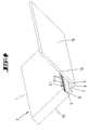
- Fig. 1 Shown and described is first with reference to Fig. 1 a hanging arrangement of foam parts 1 on a ceiling, a first embodiment concerning.
- foam parts 1 serve as a sound absorber 2 and consist of an open-cell foam, preferably of an open-celled melamine resin foam.
- Each foam part 1 is elongated formed with an elongated rectangular cross-section, wherein defined in cross-section of the longer leg perpendicular to the ceiling 3 height of the foam part 1.
- Each foam part 1 has a length which corresponds approximately to 3 times the height.
- the thickness considered transverse to the longitudinal extent corresponds to about one quarter of the foam part height.
- this mounting rails 4 For mounting on the ceiling 3 are mounted on this mounting rails 4. These have a U-shaped cross-section, wherein the U-legs connecting the U-webs serves to fix the fastening rail 4 to the ceiling 3.
- the mutually parallel U-webs are spaced from each other by a measure corresponding to the thickness of the foam part 1, so that after insertion of the foam part 1 in the mounting rail 4, the foam part 1 is clamped by means of the U-webs of the mounting rail 4.
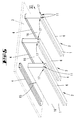
- the foam part 1 of the first embodiment has assigned to the downwardly facing free end region on a rectangular cross-section receiving space 5. This extends over the entire length of the foam part 1, opening towards the vertical end faces of the foam part 1 towards.
- the receiving space 5 is spaced from the downwardly facing end face 6 of the foam part 1 leaving a foam wall 7.
- This has a transverse to the width direction of the foam part 1 considered material thickness, which corresponds to one-tenth of the foam part width, so in the illustrated embodiment, 5 mm at a foam part width of 50 mm.
- the receiving space 5 is also flanked by foam walls 8, 9. Their thickness corresponds to about one fifth of the foam width, in the illustrated embodiment about 10 mm.
- the transversely to the foam part width considered height of the receiving space 5 corresponds in the illustrated embodiment, about 3 times the material thickness of the lower foam wall 7, so on about 15 mm.
- the lateral foam wall 9 is part of a flap wall 10. This extends from the, the end face 6 associated foam wall 7, starting in cross-section while maintaining the material thickness of the wall 9 over the entire height of the foam part 1, further over the entire length of the foam part. 1 By pivoting the flap wall 10 is an exposure of the receiving space 5 can be reached, which further under one piece, uniform material configuration of folding wall 10 and foam part 1 pivoting the flap wall 10 is achieved solely by the flexible design of the foam (see. Fig. 4 ).
- the receiving space closure position in which the flap wall 10 rests over the entire surface on the facing wide surface of the foam part 1 is secured in the assignment position of the foam part to the ceiling 3 by the mounting rail 4 and by the associated U-web of the mounting rail 4th
- a light-emitting element 11 is accommodated in the receiving space 5. This can be used after swinging the flap wall 10 and corresponding exposure of the receiving space 5 in this.
- the light-emitting element 11 is in the illustrated embodiment, an LED strip, with a strip-shaped base support 12, which extends over the entire length of the receiving space 5 and thus over the entire length of the foam part 1.
- a strip-shaped base support 12 which extends over the entire length of the receiving space 5 and thus over the entire length of the foam part 1.
- LED's 13 are arranged in the longitudinal extent of the foam part 1 and the base support. These are electrically connected to each other on the base support 12.
- the base support 12 contacts 14, for electrical contacting further, provided in downstream foam parts 1 lighting elements 11 and for connecting a power supply cable 15.
- the light-emitting element 11 is fixed in the illustrated embodiment, the ceiling side of the receiving space 5, d. H. with pointing down towards the receiving bottom LED's 13th
- the lighting element 11 accordingly shines in the operating state of the receiving space 5 of the foam part 1 from such that the outwardly facing, adjacent foam portions (foam walls 7 to 9) are transilluminated, resulting in a diffuse illumination of the immediate environment.
- the downwardly facing end face 6 directly opposite the LED's 13 and thus directly illuminated areas appear brighter than adjacent, indirectly illuminated areas, so that at least on the underside of the foam part 1, a visually appealing lighting structure is emerging.
- directly associated areas of the side walls 16 of the foam part 1 results preferably according to the here opposite the end face 6 associated foam wall 7 double material thickness of the foam wall 8 and 9 a gleichlingerte, diffused light band.
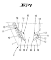
- FIGS. 5 to 7 show a second embodiment of a foam part 1. This has, associated with the side walls 16, further associated with the lower end face 6 a profiling 17. This is open-edge, ie to the each side wall 16 open toward and extends over the entire length of the foam part 1 to the respective end faces opening.
- the profiles 17 are arranged mirror-symmetrically with respect to a vertical longitudinal plane of the foam part 1 and each have an undercut.
- the profiling ceiling 18 and the profiling bottom 19 extending parallel thereto run inwards towards the end face 6 with respect to a plane aligned perpendicular to the vertical longitudinal plane and parallel to the lower end face 6, starting from the side wall opening 20, leaving a distance measure to the end face 6, which corresponds to about one fifth of the foam part width.
- the inner boundary of the profiling 17 is formed by a vertical, d. H. parallel to the associated side wall 16 extending rear wall 20.
- the distance between the mutually parallel rear walls 20 of both opposing profilings 17 corresponds in the illustrated embodiment about two-fifths of the foam part width.
- the remaining between the rear walls, central foam area carries the reference numeral 21st
- each profiling 17 and in each undercut a luminous element 11 is provided in the form of an LED strip. These are each arranged on the profiling trays 19 and inclined relative to a horizontal plane, pointing inwards.
- the LEDs 13 of the luminous element 11 tend to radiate both the rear wall 20 and the profiling ceiling 18 inwards, pointing inwards.
- the light enters indirectly via the slots in the respective side wall openings of the profiles 17 outward.
- the light also appears diffusely by reflection through the lower end face 6 of the foam part 1, possibly also by the edge webs remaining below the profilings 17.
- the reflection through the slot-like openings to the outside is supported in the illustrated embodiment by a reflection film 22 arranged on the profiling ceiling 18, for example in the form of an aluminum foil laminated on.
- Fig. 8 represents a further embodiment of a foam part 1. Also, this has according to the first embodiment in cross section on all sides of foam embraced light-emitting element 11. This sits in a receiving space 5.
- the foam part 1 is divided along a vertical longitudinal plane, starting from the upper, the mounting rail 4 attributable end face to the receiving space 5, so that one half of the foam part 1 is a flap wall 10 to expose the receiving space 5.
- foam parts 1 which also serve as a sound absorber 2 and as a light source.
- foam parts 1 can also be used as path lighting, for example for illuminating escape routes. In this case, an indirect and / or diffuse illumination is always achieved, so that a glare effect is counteracted.
Landscapes
- Engineering & Computer Science (AREA)
- Architecture (AREA)
- Civil Engineering (AREA)
- Structural Engineering (AREA)
- General Engineering & Computer Science (AREA)
- Physics & Mathematics (AREA)
- Electromagnetism (AREA)
- Non-Portable Lighting Devices Or Systems Thereof (AREA)
- Arrangement Of Elements, Cooling, Sealing, Or The Like Of Lighting Devices (AREA)
- Soundproofing, Sound Blocking, And Sound Damping (AREA)
Applications Claiming Priority (1)
| Application Number | Priority Date | Filing Date | Title |
|---|---|---|---|
| DE202008008896U DE202008008896U1 (de) | 2008-10-27 | 2008-10-27 | Schaumstoffteil sowie hängend befestigter Schallabsorber |
Publications (2)
| Publication Number | Publication Date |
|---|---|
| EP2180109A2 true EP2180109A2 (fr) | 2010-04-28 |
| EP2180109A3 EP2180109A3 (fr) | 2013-04-10 |
Family
ID=41527679
Family Applications (1)
| Application Number | Title | Priority Date | Filing Date |
|---|---|---|---|
| EP09173792.4A Withdrawn EP2180109A3 (fr) | 2008-10-27 | 2009-10-22 | Elément en mousse et absorbeur phonique fixé de manière suspendue |
Country Status (3)
| Country | Link |
|---|---|
| US (1) | US8287146B2 (fr) |
| EP (1) | EP2180109A3 (fr) |
| DE (1) | DE202008008896U1 (fr) |
Cited By (6)
| Publication number | Priority date | Publication date | Assignee | Title |
|---|---|---|---|---|
| DE202014101264U1 (de) | 2014-02-20 | 2014-04-22 | Mm Infra Gmbh & Co. Kg | Befestigungsmittel für das Aufhängen von Schallabsorbern und Schallabsorbersystem |
| CN104912215A (zh) * | 2015-06-02 | 2015-09-16 | 北新集团建材股份有限公司 | 一种立挂式矿棉吸声板吊装结构 |
| WO2015162030A1 (fr) | 2014-04-25 | 2015-10-29 | Koninklijke Philips N.V. | Panneau acoustique électroluminescent et système d'éclairage comprenant un ensemble de tels panneaux |
| DE202016101469U1 (de) | 2016-03-16 | 2016-04-26 | Mm Infra Gmbh & Co. Kg | Befestigungsmittel für das Aufhängen von Schallabsorbern und Schallabsorbersystem |
| DE202021102765U1 (de) | 2021-05-20 | 2021-06-29 | Mm Infra Gmbh & Co. Kg | Befestigungsmittel für das Aufhängen von Schallabsorbern, Befestigungssystem und Schallschutzsystem |
| EP4092210A1 (fr) | 2021-05-20 | 2022-11-23 | MM Infra GmbH & Co. KG | Moyen de fixation pour l'accrochage des absorbeurs sonores, système de fixation et système de protection sonore |
Families Citing this family (36)
| Publication number | Priority date | Publication date | Assignee | Title |
|---|---|---|---|---|
| AT509687B1 (de) * | 2010-04-09 | 2012-04-15 | Hierzer Andreas | Trennwand mit integrierter beleuchtung |
| EP2792936B1 (fr) * | 2010-09-30 | 2019-11-06 | Signify Holding B.V. | Dispositif d'éclairage |
| DE102011101913A1 (de) * | 2011-05-18 | 2012-11-22 | Bosig Gmbh | Schallabsorbierende Leuchte |
| DE102011051727A1 (de) | 2011-07-11 | 2013-01-17 | Pinta Acoustic Gmbh | Verfahren und Vorrichtung zur aktiven Schallmaskierung |
| DE202011104144U1 (de) | 2011-08-06 | 2011-11-24 | Ridi-Leuchten Gmbh | Leuchte |
| EP2573461A1 (fr) * | 2011-09-22 | 2013-03-27 | Koninklijke Philips Electronics N.V. | Ensemble d'éclairage acoustique |
| CN105189886B (zh) * | 2012-06-20 | 2017-03-15 | 皇家飞利浦有限公司 | 具有照明性质的声学面板 |
| US8967823B2 (en) * | 2012-09-13 | 2015-03-03 | Rpg Diffusor Systems, Inc. | Combination light diffuser and acoustical treatment and listening room including such fixtures |
| CH708188A2 (de) * | 2013-05-29 | 2014-12-15 | Sonami Ag | Schalldämmplatte mit Leuchtmittel. |
| USD916348S1 (en) | 2013-11-15 | 2021-04-13 | 3Form, Llc | Light-weight lighting fixture |
| USD917079S1 (en) | 2013-11-15 | 2021-04-20 | 3Form, Llc | Thin baffle |
| USD959030S1 (en) | 2013-11-15 | 2022-07-26 | 3Form, Llc | Baffle with slit end |
| USD915632S1 (en) | 2013-11-15 | 2021-04-06 | 3Form, Llc | Baffle with reduced height |
| US10889987B2 (en) | 2017-05-19 | 2021-01-12 | 3Form, Llc | Felt baffle with snap ends |
| BE1021608B1 (nl) * | 2014-09-15 | 2015-12-18 | Isomo N.V. | Lichtarmatuur uit melamineschuim |
| USD915631S1 (en) | 2014-11-14 | 2021-04-06 | 3Form, Llc | Baffle with closed ends |
| MX393990B (es) * | 2014-12-18 | 2025-03-24 | Armstrong World Ind Inc | Sistema de techo e iluminacion integrado. |
| DE202015100526U1 (de) * | 2015-02-04 | 2016-05-09 | Pinta Acoustic Gmbh | Plattenförmiges Schallabsorptionselement |
| USD915634S1 (en) | 2015-05-28 | 2021-04-06 | 3Form, Llc | Tall baffle |
| DE202015103100U1 (de) * | 2015-06-12 | 2016-09-14 | Pinta Acoustic Gmbh | An der Decke eines Gebäuderaumes anbringbarer Schallabsorber |
| US10174920B2 (en) | 2016-05-20 | 2019-01-08 | John Gibson | Safety device with lighting element and magnetic attachment |
| DE202017102765U1 (de) * | 2017-05-09 | 2017-06-19 | Maschinenfabrik Georg Kiefer GmbH, Luft- und Klimatechnik | Akustiksegel mit LEDs |
| FI11839U1 (fi) * | 2017-05-24 | 2017-10-24 | Aurinkopuro Oy | Akustinen valoelementti |
| RU2683193C1 (ru) * | 2018-05-18 | 2019-03-26 | Никита Сергеевич Медвехкв | Звукорассеивающая конструкция, оснащенная источником света |
| EP3853520B8 (fr) * | 2018-09-21 | 2025-12-03 | Fischer Lighting Holding ApS | Dispositif d'éclairage modulaire |
| PL3769971T3 (pl) * | 2019-07-23 | 2025-02-17 | Visound Acustica Sa | Warstwa dostrajająca dźwięk i panel do akustycznej adaptacji pomieszczenia |
| JP7511210B2 (ja) * | 2019-10-18 | 2024-07-05 | 株式会社キルトプランニングオフィス | 照明システム |
| CN114901995B (zh) * | 2020-01-02 | 2025-01-10 | 昕诺飞控股有限公司 | T-led含气灯管 |
| US11869474B2 (en) * | 2020-02-10 | 2024-01-09 | Lumenwerx Ulc. | Sound absorbing light fixture |
| DE202020101867U1 (de) | 2020-04-06 | 2021-07-13 | Pinta Acoustic Gmbh | Schallabsorber |
| EP4305341B1 (fr) * | 2021-03-11 | 2025-04-09 | Signify Holding B.V. | Dispositif d'éclairage, élément optique et luminaire |
| USD1062002S1 (en) | 2022-08-22 | 2025-02-11 | 3Form, Llc | X-shaped light fixture |
| USD1054617S1 (en) | 2022-08-22 | 2024-12-17 | 3Form, Llc | T-shaped light fixture |
| USD1062004S1 (en) | 2022-08-22 | 2025-02-11 | 3Form, Llc | Y-shaped light fixture |
| USD1062003S1 (en) | 2022-08-22 | 2025-02-11 | 3Form, Llc | Hexagonal-shaped light fixture |
| DE202024102144U1 (de) * | 2024-04-26 | 2024-05-08 | Briloner Leuchten GmbH & Co. KG | Diffusorprofil, Beleuchtungssystem für ein Akustikpaneel und Akustikpaneel |
Citations (1)
| Publication number | Priority date | Publication date | Assignee | Title |
|---|---|---|---|---|
| DE1214850B (de) | 1958-07-29 | 1966-04-21 | Nova Lux Ges | Schallschluckende Verkleidung von Raumflaechen, insbesondere Decken, ausgestattet mit Lichtquellen |
Family Cites Families (8)
| Publication number | Priority date | Publication date | Assignee | Title |
|---|---|---|---|---|
| US4330691A (en) * | 1980-01-31 | 1982-05-18 | The Futures Group, Inc. | Integral ceiling tile-loudspeaker system |
| DE8126423U1 (de) * | 1981-09-11 | 1982-01-28 | Kunststoffwerk Philippine Gmbh & Co Kg, 5420 Lahnstein | Schallschluckelement |
| DE29520619U1 (de) * | 1995-12-28 | 1996-02-15 | Seufert, Hans, 97618 Wollbach | Deckensystem |
| DE29815712U1 (de) * | 1997-09-04 | 1999-04-01 | Fraunhofer-Gesellschaft zur Förderung der angewandten Forschung eV, 80636 München | Schallabsorber |
| DE20007958U1 (de) * | 2000-05-03 | 2000-08-03 | Brinkmann, Udo, 49328 Melle | Möbelkörper |
| US6845841B2 (en) * | 2001-07-06 | 2005-01-25 | Aluralex Acoustics | Acoustic isolator |
| US20040128932A1 (en) * | 2003-01-07 | 2004-07-08 | Roberto Estape | Foam wall system |
| KR100571539B1 (ko) * | 2004-06-30 | 2006-04-24 | 김배영 | 흡음 블록 및 그 시공 방법 |
-
2008
- 2008-10-27 DE DE202008008896U patent/DE202008008896U1/de not_active Expired - Lifetime
-
2009
- 2009-10-22 EP EP09173792.4A patent/EP2180109A3/fr not_active Withdrawn
- 2009-10-23 US US12/589,453 patent/US8287146B2/en not_active Expired - Fee Related
Patent Citations (1)
| Publication number | Priority date | Publication date | Assignee | Title |
|---|---|---|---|---|
| DE1214850B (de) | 1958-07-29 | 1966-04-21 | Nova Lux Ges | Schallschluckende Verkleidung von Raumflaechen, insbesondere Decken, ausgestattet mit Lichtquellen |
Cited By (9)
| Publication number | Priority date | Publication date | Assignee | Title |
|---|---|---|---|---|
| DE202014101264U1 (de) | 2014-02-20 | 2014-04-22 | Mm Infra Gmbh & Co. Kg | Befestigungsmittel für das Aufhängen von Schallabsorbern und Schallabsorbersystem |
| DE102014102162A1 (de) | 2014-02-20 | 2015-08-20 | Mm Infra Gmbh & Co. Kg | Befestigungsmittel für das Aufhängen von Schallabsorbern und Schallabsorbersystem |
| EP2910800A1 (fr) | 2014-02-20 | 2015-08-26 | MM Infra GmbH & Co. KG | Moyen de fixation pour la suspension d'isolants acoustiques et système d'isolant acoustique |
| WO2015162030A1 (fr) | 2014-04-25 | 2015-10-29 | Koninklijke Philips N.V. | Panneau acoustique électroluminescent et système d'éclairage comprenant un ensemble de tels panneaux |
| US9851094B2 (en) | 2014-04-25 | 2017-12-26 | Philips Lighting Holding B.V. | Light-emitting acoustic panel and lighting system comprising a set of such panels |
| CN104912215A (zh) * | 2015-06-02 | 2015-09-16 | 北新集团建材股份有限公司 | 一种立挂式矿棉吸声板吊装结构 |
| DE202016101469U1 (de) | 2016-03-16 | 2016-04-26 | Mm Infra Gmbh & Co. Kg | Befestigungsmittel für das Aufhängen von Schallabsorbern und Schallabsorbersystem |
| DE202021102765U1 (de) | 2021-05-20 | 2021-06-29 | Mm Infra Gmbh & Co. Kg | Befestigungsmittel für das Aufhängen von Schallabsorbern, Befestigungssystem und Schallschutzsystem |
| EP4092210A1 (fr) | 2021-05-20 | 2022-11-23 | MM Infra GmbH & Co. KG | Moyen de fixation pour l'accrochage des absorbeurs sonores, système de fixation et système de protection sonore |
Also Published As
| Publication number | Publication date |
|---|---|
| US8287146B2 (en) | 2012-10-16 |
| DE202008008896U1 (de) | 2010-03-18 |
| US20100110674A1 (en) | 2010-05-06 |
| EP2180109A3 (fr) | 2013-04-10 |
Similar Documents
| Publication | Publication Date | Title |
|---|---|---|
| EP2180109A2 (fr) | Elément en mousse et absorbeur phonique fixé de manière suspendue | |
| EP3137812B1 (fr) | Système de chemin lumineux | |
| DE102014112657B4 (de) | Leuchte für ein Lichtbandsystem | |
| EP2360330B1 (fr) | Connecteur de plinthes | |
| DE202011104306U1 (de) | Alu-Profilschienen-System für LED-Stripes sowie LED-Leuchte | |
| EP2247892A1 (fr) | Luminaire | |
| AT520129B1 (de) | Lichttechnische Abdeckung für Langfeldleuchten | |
| DE202016100265U1 (de) | Anordnung zum Bilden eines länglichen Aufnahmeraums für Beleuchtungseinheiten | |
| EP3217067B1 (fr) | Système d'éclairage | |
| DE19719184C1 (de) | Leuchte | |
| DE102016101461B4 (de) | Zargenprofil für ein Türelement in einem Trennwandsystem | |
| EP2924337B1 (fr) | Éclairage doté d'une guide d'onde pour générer de la lumière anti-éblouissement sur une région partielle | |
| DE102005032629A1 (de) | Türdichtung | |
| DE102016101464B4 (de) | Verglasungsprofil für Fixglaselemente | |
| DE3643075A1 (de) | Vorhangbeleuchtung | |
| DE202010001579U1 (de) | Beleuchtungsvorrichtung für ein bewegliches Möbelelement sowie Möbelelement | |
| DE102016000225A1 (de) | Tür- oder Wandelement | |
| DE8633747U1 (de) | Vorhangbeleuchtung | |
| DE102006022211B4 (de) | Hinterleuchtetes Wandelemente-System | |
| EP4194640B1 (fr) | Plinthe éclairée, en particulier plinthe de sol | |
| DE202013005155U1 (de) | Leuchtkasten | |
| DE202011106731U1 (de) | Paneel-Vorrichtung für einen Schrank | |
| EP2622269A1 (fr) | Lampe à del comprenant une source de lumière remplaçable | |
| DE1589187C (de) | Langfeldleuchte | |
| DE202015101666U1 (de) | Plattenförmige Leuchte |
Legal Events
| Date | Code | Title | Description |
|---|---|---|---|
| PUAI | Public reference made under article 153(3) epc to a published international application that has entered the european phase |
Free format text: ORIGINAL CODE: 0009012 |
|
| AK | Designated contracting states |
Kind code of ref document: A2 Designated state(s): AT BE BG CH CY CZ DE DK EE ES FI FR GB GR HR HU IE IS IT LI LT LU LV MC MK MT NL NO PL PT RO SE SI SK SM TR |
|
| AX | Request for extension of the european patent |
Extension state: AL BA RS |
|
| PUAL | Search report despatched |
Free format text: ORIGINAL CODE: 0009013 |
|
| AK | Designated contracting states |
Kind code of ref document: A3 Designated state(s): AT BE BG CH CY CZ DE DK EE ES FI FR GB GR HR HU IE IS IT LI LT LU LV MC MK MT NL NO PL PT RO SE SI SK SM TR |
|
| AX | Request for extension of the european patent |
Extension state: AL BA RS |
|
| RIC1 | Information provided on ipc code assigned before grant |
Ipc: E04B 9/36 20060101AFI20130301BHEP Ipc: F21S 2/00 20060101ALI20130301BHEP |
|
| STAA | Information on the status of an ep patent application or granted ep patent |
Free format text: STATUS: THE APPLICATION IS DEEMED TO BE WITHDRAWN |
|
| 18D | Application deemed to be withdrawn |
Effective date: 20130503 |