EP2180112A2 - Mörtelplatte mit verringerter Dicke und Verfahren zur Herstellung besagter Mörtelplatte - Google Patents
Mörtelplatte mit verringerter Dicke und Verfahren zur Herstellung besagter Mörtelplatte Download PDFInfo
- Publication number
- EP2180112A2 EP2180112A2 EP09382195A EP09382195A EP2180112A2 EP 2180112 A2 EP2180112 A2 EP 2180112A2 EP 09382195 A EP09382195 A EP 09382195A EP 09382195 A EP09382195 A EP 09382195A EP 2180112 A2 EP2180112 A2 EP 2180112A2
- Authority
- EP
- European Patent Office
- Prior art keywords
- panel
- elements
- tubular
- filiform
- tubular elements
- Prior art date
- Legal status (The legal status is an assumption and is not a legal conclusion. Google has not performed a legal analysis and makes no representation as to the accuracy of the status listed.)
- Withdrawn
Links
- 238000004519 manufacturing process Methods 0.000 title claims abstract description 14
- 238000000034 method Methods 0.000 title claims abstract description 14
- 239000004570 mortar (masonry) Substances 0.000 title claims description 9
- 239000002184 metal Substances 0.000 claims abstract description 39
- 239000000463 material Substances 0.000 claims abstract description 37
- 230000003014 reinforcing effect Effects 0.000 claims abstract description 13
- 229910001220 stainless steel Inorganic materials 0.000 claims abstract description 10
- 239000010935 stainless steel Substances 0.000 claims abstract description 10
- 238000010079 rubber tapping Methods 0.000 claims description 14
- 239000002984 plastic foam Substances 0.000 claims description 12
- 238000003466 welding Methods 0.000 claims description 11
- 238000004873 anchoring Methods 0.000 claims description 10
- 238000005553 drilling Methods 0.000 claims description 4
- 230000002787 reinforcement Effects 0.000 description 8
- 239000011083 cement mortar Substances 0.000 description 3
- 239000004567 concrete Substances 0.000 description 3
- 238000002347 injection Methods 0.000 description 3
- 239000007924 injection Substances 0.000 description 3
- 238000000926 separation method Methods 0.000 description 3
- 230000015572 biosynthetic process Effects 0.000 description 2
- 239000000919 ceramic Substances 0.000 description 2
- 150000001875 compounds Chemical class 0.000 description 2
- 238000009826 distribution Methods 0.000 description 2
- 238000003754 machining Methods 0.000 description 2
- 210000002435 tendon Anatomy 0.000 description 2
- 229910000831 Steel Inorganic materials 0.000 description 1
- 230000005540 biological transmission Effects 0.000 description 1
- 239000004568 cement Substances 0.000 description 1
- 239000007795 chemical reaction product Substances 0.000 description 1
- 238000010276 construction Methods 0.000 description 1
- 238000005260 corrosion Methods 0.000 description 1
- 230000007797 corrosion Effects 0.000 description 1
- 239000013536 elastomeric material Substances 0.000 description 1
- 239000004794 expanded polystyrene Substances 0.000 description 1
- 238000009434 installation Methods 0.000 description 1
- 238000009413 insulation Methods 0.000 description 1
- 230000010354 integration Effects 0.000 description 1
- 239000011513 prestressed concrete Substances 0.000 description 1
- 239000010959 steel Substances 0.000 description 1
- 230000007306 turnover Effects 0.000 description 1
Images


Classifications
-
- E—FIXED CONSTRUCTIONS
- E04—BUILDING
- E04C—STRUCTURAL ELEMENTS; BUILDING MATERIALS
- E04C2/00—Building elements of relatively thin form for the construction of parts of buildings, e.g. sheet materials, slabs, or panels
- E04C2/02—Building elements of relatively thin form for the construction of parts of buildings, e.g. sheet materials, slabs, or panels characterised by specified materials
- E04C2/04—Building elements of relatively thin form for the construction of parts of buildings, e.g. sheet materials, slabs, or panels characterised by specified materials of concrete or other stone-like material; of asbestos cement; of cement and other mineral fibres
- E04C2/06—Building elements of relatively thin form for the construction of parts of buildings, e.g. sheet materials, slabs, or panels characterised by specified materials of concrete or other stone-like material; of asbestos cement; of cement and other mineral fibres reinforced
-
- E—FIXED CONSTRUCTIONS
- E04—BUILDING
- E04B—GENERAL BUILDING CONSTRUCTIONS; WALLS, e.g. PARTITIONS; ROOFS; FLOORS; CEILINGS; INSULATION OR OTHER PROTECTION OF BUILDINGS
- E04B1/00—Constructions in general; Structures which are not restricted either to walls, e.g. partitions, or floors or ceilings or roofs
- E04B1/38—Connections for building structures in general
- E04B1/41—Connecting devices specially adapted for embedding in concrete or masonry
Definitions
- the invention relates to a process for the manufacture of a lightweight panel of a resistant and settable material, with reduced thickness, as well as to the panel obtained by said process.
- the lightweight panel is provided with reinforcing filiform elements embedded therein as well as with a plurality of anchoring elements for securing the panel, by its non-visible face, to a supporting structure, being suitable for the construction of outdoor (façades) and indoor enclosures, for the covering of walls, the formation of raised floors, of street furniture, etc.
- United States patent US 6711866 describes a prestressed concrete panel with a thickness of approximately 1.5 inches.
- the prestressed tendons extend in two perpendicular directions, like a grid, placed on each side of the mid-plane of the panel and spaced from said mid-plane so as to increase the strength of the panel and prevent its warping.
- the panel is provided with anchors or connectors embedded in the panel and provided with an internally threaded hollow cylindrical body the open end of which is communicated with the outer surface of the non-visible face of the panel.
- the securing of the panel to a structure of the building is carried out by interposing a metal strip between the surface of the non-visible face of the panel and the outer surface of said structure, said strip being bent like a bar, establishing a separation distance between both surfaces.
- the bar is fixed at one end to the structure, by means of a fixing screw, and at the other end to the non-visible face of the panel, by means of a lock screw the outer thread of which is suitable for fitting in the inner thread of the cylindrical body embedded in the panel.
- the cylindrical body is partially introduced traversing a plate two of the edges of which are inwardly bent to engage a pair of prestressed parallel tendons of the panel.
- a mortar panel with reduced thickness is the one described in Spanish utility model ES 1065420U , biaxially reinforced by means of two bands of prestressed rods which orthogonally cross one another forming a grid, at the crossing points of which the rods of one band are not joined with those of the other band.
- Said panel comprises securing means for its securing to the structure of the building which are occluded in the mortar mass and intercalated in the space of any of the squares of the grid.
- Said securing means are made up of parts formed by a disc-shaped base, followed by a cylindrical segment internally provided with a threaded blind hole.
- the base in the form of a flange acts as a retainer of the securing means in the settable mass, whereas the cylindrical segment acts as an anchor since it can attach the panel to the structure of the building when a correspondingly threaded fixing screw is inserted.
- the parts in the form of a flange of the securing means centred in some of the squares of the reinforcement and to support said means by holding means through anchoring stems screwed in the holes, such that the free end of the cylindrical segment is flush with what will be the surface of the non-visible face of the panel.
- the previously described securing means are manufactured in a material of the group comprising cement compounds and compounds used in ceramics.
- the previously described securing means assure the reliability of the securing of the panel, they give rise to high costs in the manufacture thereof as well as costs derived from the process for manufacturing the panel since, in the case of metal securing means, a precise machining process is necessary, and in the case of ceramic securing means, the intervention of a machine holding said means in the centred position in the squares and at a certain distance from the base of the mould (visible face of the panel), before the pouring and during the material setting process, is necessary.
- the panel object of the invention is made of a resistant and settable material, has a reduced thickness, and is provided with reinforcing filiform elements embedded therein and with a plurality of anchors intended to secure the panel, by its non-visible face, to a supporting structure.
- each tubular element is integrally joined to respective first filiform elements.
- the integral joint between the tubular elements and the first filiform elements is a joint by welding. This considerably simplifies the manufacturing method of the panel, since it allows positioning the anchors for the securing to the actual reinforcement without having to use auxiliary machinery keeping them in position during the pouring of the settable material of the panel and its setting process.
- the two layers forming the reinforcing filiform elements are integral at their crossing points, forming an electrowelded mesh.
- the tubular elements have a cavity at least partially occupied by a plastic foam material.
- the panel thus constructed allows being stacked one on top of the other before the fixing to the anchors of the sheet metal strip by means of the sheet metal screw, saving space in the transport of several units of panels, since there is no element projecting from the non-visible face.
- the placement of the mentioned sheet strip can be carried out subsequently, even on-site.
- Said sheet metal or self-tapping screws are furthermore self-drilling screws, which facilitates the placement of the sheet metal strip and its fixing to the supporting structure.
- a process for the manufacture of the panel object of the invention described above is disclosed, which is essentially characterized in that it comprises the following steps:
- the mentioned process allows a quick and clean manufacture of the panel object of the invention without needing to use complex machinery. Furthermore, the injection under pressure of the settable material favours the compactability of the panel and prevents small unfilled spaces from remaining inside it, overcoming the structural problems that this would involve.
- the anchoring tubular elements are partially filled with a plastic foam material, before or after they are attached by welding to the filiform elements of the mesh, leaving the areas close to the open ends of the tubular elements unfilled so that the resistant material injected in step c) penetrates through said open ends in the tubular elements.
- step d) is carried out in a setting chamber at a temperature comprised between 40 o C and 60 o C.
- sheet metal strips are attached to the outer bases of some tubular elements by means of respective sheet metal or self-tapping (and optionally, self-drilling) screws, which sheet metal strips are provided with a step, such that between the sheet strips and the mentioned outer bases there is a space suitable for receiving the end of a profile of the supporting structure from which the panel will be suspended in its placement and fixing.
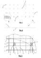
- Figs. 1 and 2 show the high-strength mortar panel 1 with reduced thickness, comprised between 12 and 25 mm from the visible face 4 to the non-visible face 5 of said panel 1.
- the depicted panel 1 measures 2400 x 1200 mm, with a thickness of 20 mm. Due to its technical features, which will be described below, said panel 1 is indicated for the covering of outdoor (facades) and indoor enclosures, as shown in Figs. 5 to 7 , of walls, for the formation of raised floors, of street furniture, etc.
- the configurations of the panel 1 are varied according to the use and location thereof.
- the panel 1 depicted in Fig. 17 corresponds to a corner panel, therefore it has a curved shape.
- the panel 1 of Fig. 1 has been depicted with the bottom left corner lacking the settable material, high-strength mortar, for the purpose of being able to see the reinforcement of said panel 1.
- the panel 1 is reinforced with a plurality of first filiform elements 2, arranged parallel to the shortest side of the panel 1, and by a plurality of second filiform elements 3 perpendicular to the first ones, forming a grid of two layers which are integrally joined at the crossing points of the filiform elements 2 and 3.
- the mentioned filiform elements 2 and 3 are made of stainless steel and form an electrowelded mesh, preventing corrosion problems and saving labour costs in the manufacturing process, since there is no prestressed or post-stressed reinforcement which usually increases the cost of the end product due to the operations and control that it involves.
- Fig. 1 shows the distribution of a plurality of anchors, separated every 300 mm, intended to secure the panel 1 by its non-visible face 5 to a supporting structure 16 (see Figs. 5 to 7 ).
- These anchors comprise metal tubular elements 6 made of stainless steel, with open ends and an essentially rectangular cross-section, as can be seen in Fig. 4 .
- Each of said tubular elements 6 has two opposite rectangular bases, in which the outer base 7 is flush with the non-visible face 5 of the panel 1, whereas the inner base 8 is oriented towards the visible face 4 of the panel 1 ( Fig. 2 ).
- Each of the side faces 9 of the tubular element 6 is integrally attached, by means of welding, to a respective first filiform element 2, whereby the position of the tubular element 6 is assured with respect to the mesh of the reinforcement of the panel 1.
- Both Fig. 3 and Fig. 4 show that the separations between the reinforcing bars forming the mesh have been adjusted so that each tubular element 6 is framed by two first filiform elements 2 (welded to the side faces 9) and by two second filiform elements 3.
- the mentioned pair of second filiform elements 3 is arranged flanking the two open ends of the tubular element 6 and, optionally, can be attached to said ends by means of spot welds in those segments of contact.
- tubular elements 6 are also made of steel, with a rectangular cross-section, and have their outer bases 7 flush with the non-visible face 5 of the panel 1, has been contemplated in Fig. 16 .
- the inner base 8 of each tubular element 6 is integrally attached to a first filiform element 2, in a segment close to the crossing of the latter with a second filiform element 3, and one of the side faces 9 of said tubular element 6 is integrally attached by welding to a second filiform element 3 (see detail F).
- tubular elements 6 is occupied by a plastic foam material 10, for example expanded polystyrene, whereas the ends of said tubular elements 6 are occupied by the resistant and settable material of the panel 1, in this case, a high-strength mortar with a minimum strength value of 50 N/mm 2 .
- a high-strength mortar with a minimum strength value of 50 N/mm 2 .
- the anchors of the panel 1 also comprise suspending means formed by a sheet metal strip 11 provided with a step.
- Each strip 11 is supported on the outer base 7 of a tubular element 6 and is fixedly attached to said tubular element 6 by means of two sheet metal or self-tapping screws 12, preferably self-drilling ones, which, traversing the outer base 7, are introduced in the plastic foam material 10 of the inside of the cavity of the tubular element 6. Said assembly is observed in detail in Figs. 8, 9 , in detail E of Fig. 14 and in Fig.
- the stepped shape of the strip 11 creates a space between the outer base 7 of the tubular element 6 and said strip 11 that is suitable for receiving the end of a profile 13 of the supporting structure 16 from which the panel 1 is suspended, with the interposition of an adjustment portion 14 manufactured in an elastomeric material which, in addition to adjusting the assembly, prevents the transmission of vibrations and favours the electric insulation between the parts involved.
- Fig. 8 corresponding to detail B of Fig. 6 , shows how two panels 1 are secured at the lower and upper part.
- a panel 1 such as those depicted in Figs. 1, 2 and 5 to 7
- strips 11 fixed with sheet metal screws 12 in the outer bases 7 of some of the tubular elements 6 of a lower horizontal alignment of the panel 1 will be placed.
- the strips 11 will be placed, for example, every two tubular elements 6.
- respective "omega" profiles 13 of a small depth see Figs. 8 , 10 , 11 , 14 and 15 ) will be fixed in the corresponding vertical posts 17.
- the panel 1 For the placement and fixing of the panel 1 to the profiles 13 of the supporting structure 16, the panel 1 must simply be raised, such that the alignments of strips 11 are above the upper ends of the profiles 13, as shown Fig. 15 , and subsequently be lowered such that said ends occupy the space existing between the steps of the strips 11 (free ends surrounded by the adjustment portions 14) and the outer bases 7 of the tubular elements 6, until it abuts (see detail E of Fig. 14 ).
- the pair of upper sheet metal screws 19 of Fig. 13 correspond to those fixing the profile 18 to a post 17, whereas the pair of lower sheet metal screws 19 correspond to those fixing said profile 18 to the outer base 7 of a tubular element 6 of the panel 1, as observed in detail D of Fig. 14 .
- the upper fixing (detail D of Fig. 14 ) of the panel 1 assures that the latter will not be able to turn over with respect to the lower fixing (detail E of Fig. 14 ).
- the inside of the cavity of the anchoring tubular elements 6 is filled with a plastic foam material 10, such that the only segments of the tubular elements 6 without filling are those of the areas close to their open ends.
- each tubular element 6 there is distinguished an outer base 7, which will be flush with the non-visible face 5 of the panel 1, and at least one of the side faces 9 of the tubular element 6 which will be integrally attached to a first filiform element 2.
- the panel 1 has all its tubular elements 6 framed by two first filiform elements 2, to which they are welded, and by two second filiform elements 3 in a perpendicular direction.
- the electrowelded mesh forms the reinforcement of the panel 1 since it must take into account the separations between the first filiform elements 2 and the second filiform elements 3 so that the tubular elements 6 can be fixed by welding in some of the grids thereof, welding the side faces 9 to the first filiform elements 2 of said grids.
- cement mortar with a minimum strength of 50 N/mm 2
- said material is injected under pressure through one or more inlet openings provided in the mould, the injection ending when the entire inner space between the two half-moulds is completely full.
- the injection favours that the panel 1 with reduced thickness is very compact, reducing to a minimum the possibilities of any small hollow remaining unfilled inside any segment of the panel 1.
- said panel 1 After demoulding the panel 1 by decoupling it from the two half-moulds, said panel 1 can be stored on top of other panels 1, since there is no element projecting from the surface thereof which hinders stacking.
- the panels 1 are suspended from the upper ends of the profiles 13, since they are inserted within the spaces left between the sheet metal strips 11 attached by means of corresponding sheet metal or self-tapping screws 12 to the outer bases 7 of some tubular elements 6 and their corresponding fillings of plastic foam material 10.
Landscapes
- Engineering & Computer Science (AREA)
- Architecture (AREA)
- Civil Engineering (AREA)
- Structural Engineering (AREA)
- Physics & Mathematics (AREA)
- Electromagnetism (AREA)
- Panels For Use In Building Construction (AREA)
Applications Claiming Priority (1)
| Application Number | Priority Date | Filing Date | Title |
|---|---|---|---|
| ES200802972A ES2320306B1 (es) | 2008-10-22 | 2008-10-22 | Panel de mortero de reducido espesor y procedimiento de fabricacion del mismo. |
Publications (1)
| Publication Number | Publication Date |
|---|---|
| EP2180112A2 true EP2180112A2 (de) | 2010-04-28 |
Family
ID=40719045
Family Applications (1)
| Application Number | Title | Priority Date | Filing Date |
|---|---|---|---|
| EP09382195A Withdrawn EP2180112A2 (de) | 2008-10-22 | 2009-10-05 | Mörtelplatte mit verringerter Dicke und Verfahren zur Herstellung besagter Mörtelplatte |
Country Status (2)
| Country | Link |
|---|---|
| EP (1) | EP2180112A2 (de) |
| ES (1) | ES2320306B1 (de) |
Citations (3)
| Publication number | Priority date | Publication date | Assignee | Title |
|---|---|---|---|---|
| US6711866B2 (en) | 2000-10-06 | 2004-03-30 | Brian M. Blount | Thin prestressed concrete panel and apparatus for making the same |
| ES1065420U (es) | 2007-05-14 | 2007-08-16 | Carlos Fradera Pellicer | Panel de mortero con armadura biaxial pretensada. |
| ES1066496U (es) | 2007-10-11 | 2008-02-01 | Carlos Fradera Pellicer | "taco versatil para paneles prefabricados". |
Family Cites Families (7)
| Publication number | Priority date | Publication date | Assignee | Title |
|---|---|---|---|---|
| US1677372A (en) * | 1927-05-13 | 1928-07-17 | Bernard A Ruhling | Sheet rubber |
| US3248836A (en) * | 1963-06-17 | 1966-05-03 | Structural Clay Products Inst | External wall panel and wall formed therefrom |
| US4194333A (en) * | 1978-05-24 | 1980-03-25 | Butler Manufacturing Company | Attachment for mounting concrete wall panels on a building |
| JPH0228652B2 (ja) * | 1983-07-19 | 1990-06-26 | Asahi Chemical Ind | Umekomikanaguomaisetsushitakeiryokihokonkuriitopaneru |
| JP2624502B2 (ja) * | 1988-03-14 | 1997-06-25 | 小野田エー・エル・シー株式会社 | 軽量気泡コンクリートパネル用補強マットの製造方法 |
| CA2209664C (en) * | 1995-01-06 | 2005-06-07 | The Burke Group | Concrete structure having load transferring insert and method for making same |
| JP2000006134A (ja) * | 1998-06-26 | 2000-01-11 | Onoda Autoclaved Light Weight Concrete Co Ltd | アンカー用長尺プレート埋設alcパネルの製造方法及びそれにより得られるalcパネル |
-
2008
- 2008-10-22 ES ES200802972A patent/ES2320306B1/es not_active Expired - Fee Related
-
2009
- 2009-10-05 EP EP09382195A patent/EP2180112A2/de not_active Withdrawn
Patent Citations (3)
| Publication number | Priority date | Publication date | Assignee | Title |
|---|---|---|---|---|
| US6711866B2 (en) | 2000-10-06 | 2004-03-30 | Brian M. Blount | Thin prestressed concrete panel and apparatus for making the same |
| ES1065420U (es) | 2007-05-14 | 2007-08-16 | Carlos Fradera Pellicer | Panel de mortero con armadura biaxial pretensada. |
| ES1066496U (es) | 2007-10-11 | 2008-02-01 | Carlos Fradera Pellicer | "taco versatil para paneles prefabricados". |
Also Published As
| Publication number | Publication date |
|---|---|
| ES2320306B1 (es) | 2010-07-07 |
| ES2320306A1 (es) | 2009-05-20 |
Similar Documents
| Publication | Publication Date | Title |
|---|---|---|
| US4727701A (en) | Building panel | |
| US6434900B1 (en) | Prefabricated concrete wall system | |
| US8291675B2 (en) | Modular construction system and components and method | |
| RU2608827C2 (ru) | Железобетонный строительный элемент с пазом для сборки и способ его изготовления | |
| US6880304B1 (en) | Structural thermal framing and panel system for assembling finished or unfinished walls with multiple panel combinations for poured and nonpoured walls | |
| CN106703281B (zh) | 用于混凝土的外部拉伸加强装置 | |
| RO118462B1 (ro) | Constructie modulara de perete izolant termic, procedeu de realizare a constructiei si cofraj pentru aplicarea procedeului | |
| WO2016168521A1 (en) | Composite concrete and foam building component | |
| US10753109B2 (en) | Concrete form tie, and concrete formwork comprising same | |
| US11920346B2 (en) | Module and method for producing a module, a building wall and a building | |
| KR20200075599A (ko) | 피씨 더블월을 이용한 건축물의 복수층 시공방법 | |
| KR20110119473A (ko) | 프리캐스트 블록과 그 블록을 이용한 중저층 보-기둥 건물의 리모델링 보강공법 | |
| WO2016161478A1 (en) | Stay-in-place beam formwork for concrete structures | |
| US3733762A (en) | Binary precast concrete triangulated building system | |
| JP2004528497A (ja) | 強化建築用パネルおよび三角柱 | |
| KR100796808B1 (ko) | 노출콘크리트용 유로폼 거푸집과 이를 이용한 노출콘크리트시공방법 | |
| CN108026727B (zh) | 夹持件 | |
| CN110847413A (zh) | 一种预制多肋薄壁空腔剪力墙 | |
| WO2018129591A1 (en) | Integrated composite framing system | |
| US4228625A (en) | Construction system | |
| KR102120426B1 (ko) | 조립식 더블 월 pc | |
| EP2180112A2 (de) | Mörtelplatte mit verringerter Dicke und Verfahren zur Herstellung besagter Mörtelplatte | |
| RO122681B1 (ro) | Set de panouri structurale pentru realizarea unei construcţii civile şi procedeu de realizare a construcţiei | |
| RU97752U1 (ru) | Строительный модуль | |
| US20250223801A1 (en) | External walls and methods of constructing and cladding same |
Legal Events
| Date | Code | Title | Description |
|---|---|---|---|
| PUAI | Public reference made under article 153(3) epc to a published international application that has entered the european phase |
Free format text: ORIGINAL CODE: 0009012 |
|
| AK | Designated contracting states |
Kind code of ref document: A2 Designated state(s): AT BE BG CH CY CZ DE DK EE ES FI FR GB GR HR HU IE IS IT LI LT LU LV MC MK MT NL NO PL PT RO SE SI SK SM TR |
|
| AX | Request for extension of the european patent |
Extension state: AL BA RS |
|
| STAA | Information on the status of an ep patent application or granted ep patent |
Free format text: STATUS: THE APPLICATION IS DEEMED TO BE WITHDRAWN |
|
| 18D | Application deemed to be withdrawn |
Effective date: 20120503 |