EP2180125A2 - Huisserie de fenêtre ou de porte - Google Patents
Huisserie de fenêtre ou de porte Download PDFInfo
- Publication number
- EP2180125A2 EP2180125A2 EP08020148A EP08020148A EP2180125A2 EP 2180125 A2 EP2180125 A2 EP 2180125A2 EP 08020148 A EP08020148 A EP 08020148A EP 08020148 A EP08020148 A EP 08020148A EP 2180125 A2 EP2180125 A2 EP 2180125A2
- Authority
- EP
- European Patent Office
- Prior art keywords
- window
- door frame
- frame according
- side parts
- profile section
- Prior art date
- Legal status (The legal status is an assumption and is not a legal conclusion. Google has not performed a legal analysis and makes no representation as to the accuracy of the status listed.)
- Withdrawn
Links
Images


Classifications
-
- E—FIXED CONSTRUCTIONS
- E06—DOORS, WINDOWS, SHUTTERS, OR ROLLER BLINDS IN GENERAL; LADDERS
- E06B—FIXED OR MOVABLE CLOSURES FOR OPENINGS IN BUILDINGS, VEHICLES, FENCES OR LIKE ENCLOSURES IN GENERAL, e.g. DOORS, WINDOWS, BLINDS, GATES
- E06B1/00—Border constructions of openings in walls, floors, or ceilings; Frames to be rigidly mounted in such openings
- E06B1/02—Base frames, i.e. template frames for openings in walls or the like, provided with means for securing a further rigidly-mounted frame; Special adaptations of frames to be fixed therein
-
- E—FIXED CONSTRUCTIONS
- E06—DOORS, WINDOWS, SHUTTERS, OR ROLLER BLINDS IN GENERAL; LADDERS
- E06B—FIXED OR MOVABLE CLOSURES FOR OPENINGS IN BUILDINGS, VEHICLES, FENCES OR LIKE ENCLOSURES IN GENERAL, e.g. DOORS, WINDOWS, BLINDS, GATES
- E06B9/00—Screening or protective devices for wall or similar openings, with or without operating or securing mechanisms; Closures of similar construction
- E06B9/02—Shutters, movable grilles, or other safety closing devices, e.g. against burglary
- E06B9/08—Roll-type closures
- E06B9/11—Roller shutters
- E06B9/17—Parts or details of roller shutters, e.g. suspension devices, shutter boxes, wicket doors, ventilation openings
- E06B9/17007—Shutter boxes; Details or component parts thereof
Definitions
- the invention relates to a window or door frame, with a bottom part and two associated side parts.
- Window or door frames are used to facilitate the installation of windows or doors in the designated building openings.
- experiments have been made with frames made of wood, plastic or aluminum.
- these frames had the disadvantage that the required joint tightness could be achieved only with great effort and the exact positioning of the window or door was difficult.
- the invention is therefore an object of the invention to provide a window or door frame, which meets the requirements of the joint tightness and with the installation of the window or the door is facilitated.
- the side parts each have at least one cavity at least partially enclosing rail profile.
- the side parts each having a rail profile, a joint-tight installation of the window or door is made possible, which rest laterally after mounting on the side panels of the window or door frame, at the same time the window or door is automatically positioned correctly during installation, so that the installation can be made very easily and quickly.
- the two rail profiles are symmetrical and each have at least one groove or recess.
- the two opposite rail profiles give the window or door frame increased strength and stability, so that it can be made easily but stably.
- the rail profiles are glued to the side panels and / or screwed.
- the rail profile of the window or door frame according to the invention is formed in two parts and includes an inner profile section and an outer profile section.
- the rail profile can be designed as a modular system by the outer profile section with an inner profile section having a groove or recess z. B. for a roller shutter, is composed.
- the inner and outer profile section can be put together, clipped, glued, screwed, riveted or welded.
- the outer profile section may be assembled with another inner profile section having an additional groove or recess for a fly screen or screen (sunshade).
- the outer profile section is assembled with a profile section having three grooves or recesses to the rail profile.
- the rail profile in particular an inner or outer profile section, a trained as a predetermined breaking point, removable profile part which releases a recess or groove after removal.
- the profile part can be connected via areas with reduced wall thickness with the remaining part of the profile section and be broken out manually or with a tool. As a result, a groove or recess is exposed in the rail profile, in which a roller shutter, a blind, a fly screen, a Markisolette or a screen can be performed.
- An embodiment of the window or door frame according to the invention provides that the side parts have an L-shaped cross-section with a long and a short leg, wherein the short leg extends in the plane of the window or door opening.
- the two opposite rail profiles form a stop surface for a window or a door, whereby a complex alignment or positioning of the door or the window is unnecessary.
- the rail profile is made of metal, in particular steel or aluminum.
- the rail profile can also be made of plastic or wood.
- the rail profiles can be manufactured as extruded profiles.
- the side parts consist of a foamed plastic.
- a foamed plastic In particular, expandable polypropylene (EPP) or expandable polystyrene (EPS) or expandable polyethylene (EPE) can be used as the foamed plastic.
- EPP expandable polypropylene
- EPS expandable polystyrene
- EPE expandable polyethylene
- the mentioned foamed plastics may have a density between 5 kg / m 3 and 200 kg / m 3 .
- the window frame according to the invention can also be used in windows provided with a window sill, it can be provided that the side parts have a recess directed towards the window opening or a removable insert piece in the region of their end connected to the bottom part.
- the recess can either be produced by the manufacturer, alternatively, the recess can be made by the user side by separating the insert. The separation can optionally be facilitated by prefabricated punched, cuts or the like.
- the bottom part has at least one projection or a groove which serves as a stop for a window or a door.
- a correspondingly opposite trained frame portion of the window or the door can be placed or placed, whereby the window or the door is automatically positioned correctly. Since the otherwise required adjustment and review of the mounting position is eliminated, the required assembly time can be reduced with the window or door frame according to the invention.
- the window or door frame In order to further reduce the assembly work on the construction site, it may be provided in the window or door frame according to the invention that it has an attached roller shutter box as a ceiling part.
- the window or door frame with the bottom part, the two side panels and the roller shutter box is provided as a prefabricated module, which is inserted into the building opening and fastened there.
- the attachment can be done for example with screws or with an adhesive foam.
- a shutter box a top box or a masonry box can be used as a shutter box.
- the side parts each have at least one, preferably a plurality of openings.
- the openings may be circular and pass through the side panels in one or more rows. In these openings, which can be arranged distributed over the surface of the side parts, penetrates during assembly of the adhesive foam, so that a deflection of the side parts is avoided, which could otherwise be caused by the pressure of the expanding adhesive foam.
- the window or door frame according to the invention is connected in the assembled state via a particular trained as a perforated plate liner with masonry, in particular, the window or door frame with the masonry be bolted.
- the material used for the insert may be plastic, fiberglass-reinforced plastic (fiberglass), galvanized sheet steel, aluminum, titanium or stainless steel.
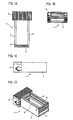
- Window frame 1 shown essentially consists of a bottom part 2 and associated side parts 3, 4.
- the bottom part 2 is perpendicular to the side parts 3, 4, so that the window frame 1 is U-shaped.
- On the side opposite the bottom part of a shutter box 5 is attached.
- the shutter box 5 is prefabricated and contains in its interior a roller shutter, which is wound on a shaft.
- the prefabricated shutter box 5 is connected to the two free ends of the side parts 3, 4, so that a prefabricated, einbaure window frame is formed.
- the shutter box 5 may be formed as a wall box or alternatively as a top box.
- the side parts 3, 4 may be connected to the bottom part 2 and the shutter box 5 by gluing and / or screwing.
- In the side parts 3, 4 each have a rail profile 8 is mounted, which consists in the illustrated embodiment made of steel and has a groove for the roller shutter, so that it is guided in the groove.
- the side parts 3, 4 are made of a foamed plastic, either expandable polypropylene (EPP), expandable polystyrene (EPS) or expandable polyethylene (EPE) can be used, each at a density of 5 kg / m 3 to 200 kg / m 3 .
- EPP expandable polypropylene
- EPS expandable polystyrene
- EPE expandable polyethylene
- the bottom part 2 and the shutter box 5 may consist of one of the mentioned foamed plastics.
- the bottom part has on its inside a parallel to the front edge extending projection 7, which serves as a stop for a window.
- the projection 7 to be inserted into the window frame 1 window can be easily positioned, since the correct position forcibly results when placed on the projection 7.
- the side parts 3, 4 have an L-shaped cross section with a long and a short leg, wherein the short leg extends in each case in the plane of the window opening.
- the side part 3 is shown in a sectional view, a side view and a perspective view.
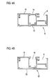
- Fig. 4A shows a rail profile 8, which is fixed to the inside of the side parts 3, 4.
- the window frame 1 is provided with the mounted rail profile 8, the sake of clarity in Fig. 1D not shown.
- the rail profile 8 encloses a cavity partially and has a groove 9. In the groove 9, arranged in the shutter box 5 roller shutter can run.
- the rail profile 8 is designed as a modular system and comprises an outer profile section 10 and an inner profile section 11.
- the two profile sections 10, 11 can be locked together, glued, screwed or connected to each other in another way.
- the outer profile section 10 is glued to the associated side part or screwed with special dowels. With the outer profile section 10, a different inner profile section can be combined in each case to allow adaptation to different purposes.
- the outer profile section 10 could also be other than the one in FIG Fig. 4A shown inner profile portion 11, for example, has an additional groove or recess for a fly screen or screen, as well it would be conceivable alternatively to use another inner profile section having three grooves or recesses. In these grooves or recesses and a Markisolette or the like can be added.
- Fig. 4B shows a further rail section 12, consisting of the outer profile section 10 and an inner profile section 13, which consists of the in Fig. 4A shown inner profile section 11 was prepared by removing a profile member 14 which releases a groove 15 after removal.
- a fly screen, a screen or the like can be accommodated in this groove 15.
- the window frame 1 is bolted to the outer profile section 10 of the rail section 8, 12 and pegged to the building wall, wherein the inner profile section 11, 13, which forms the guide and tread for the roller shutter or a blind, can be additionally screwed separately.
- Fig. 5 shows an exploded view of the items of a window frame with perforated plate and a window.
- the window frame 16 consists essentially of the bottom part 2 and side parts 17, 18. On the inside of the window designed as a molded window sill 19 is attached to the bottom part 2.
- the side parts 17, 18 each have a plurality of circular openings 20 which are arranged in a row.
- a rail profile is attached, consisting of an outer profile section 21, which is designed as a roller shutter track, and an inner profile section 22, which is designed as a flush-mounted rail.
- On the outside of the side parts 17, 18 each designed as a perforated plate 23 deposit is provided below the bottom part 2, a perforated plate 24 is attached.
- Fig. 6 shows a perspective view of the perforated plates 23, 24 and a masonry 25.
- the formed as a perforated plate 23, 24 insert may have a thickness of 0.5 mm to 5 mm, a width of 170 mm to 500 mm and depending on the intended use a height of up to 4,000 mm.
- the insert made of galvanized sheet steel, alternatively, it may be made of plastic, glass fiber reinforced plastic, aluminum, titanium or stainless steel.
- Fig. 7 shows there the window frame 16 in the attachment to the masonry 25.
- the window frame 16 was screwed by means of schematically illustrated screws 26 on the perforated plates 23, 24 with the masonry 25.
- the screws hold the outer profile section 21, the side parts 17, 18 and the perforated plates 23, 24 ah the masonry 25.
- the space between the masonry 25 and the outside of the side panels 17, 18 is foamed with an adhesive foam, with excess adhesive foam through the Openings 20 of the side parts 17, 18 can escape.
- the screwing of the inner profile section 22, whereby the rail profile results in the groove of the roller shutter is performed.
- the position of the window frame 16 can in the direction of in Fig.
- the window frame 16 can be moved in the use of a full thermal insulation in the outer insulation layer. Therefore, the window frame 16 is particularly well suited for energy-efficient houses, passive houses and the energetic renovation of old buildings.
- Fig. 8 is a perspective view and shows the window frame 16 after mounting on the masonry 25 with attached shutter box 27 after installation of the window 28th
Landscapes
- Engineering & Computer Science (AREA)
- Structural Engineering (AREA)
- Civil Engineering (AREA)
- Architecture (AREA)
- Wing Frames And Configurations (AREA)
- Support Devices For Sliding Doors (AREA)
- Refrigerator Housings (AREA)
Applications Claiming Priority (1)
| Application Number | Priority Date | Filing Date | Title |
|---|---|---|---|
| DE200820014057 DE202008014057U1 (de) | 2008-10-22 | 2008-10-22 | Fenster- oder Türzarge |
Publications (2)
| Publication Number | Publication Date |
|---|---|
| EP2180125A2 true EP2180125A2 (fr) | 2010-04-28 |
| EP2180125A3 EP2180125A3 (fr) | 2013-07-17 |
Family
ID=40279752
Family Applications (1)
| Application Number | Title | Priority Date | Filing Date |
|---|---|---|---|
| EP08020148.6A Withdrawn EP2180125A3 (fr) | 2008-10-22 | 2008-11-19 | Huisserie de fenêtre ou de porte |
Country Status (2)
| Country | Link |
|---|---|
| EP (1) | EP2180125A3 (fr) |
| DE (1) | DE202008014057U1 (fr) |
Cited By (2)
| Publication number | Priority date | Publication date | Assignee | Title |
|---|---|---|---|---|
| EP3336295A1 (fr) | 2016-12-16 | 2018-06-20 | Modulotherm Sp. z o.o. | Profilé pour agrandir une porte ou une fenêtre |
| WO2022226609A1 (fr) * | 2021-04-26 | 2022-11-03 | Jose Sabadin Uldemar | Ensemble cadre monobloc universel avec finitions à vue interne et externe et mousse d'étanchéité |
Families Citing this family (2)
| Publication number | Priority date | Publication date | Assignee | Title |
|---|---|---|---|---|
| FR2991356B1 (fr) * | 2012-06-04 | 2014-07-18 | Laurent Charvoz | Procede de realisation d'un panneau de construction modulaire avec menuiserie integree, pre-cadre necessaire et panneau obtenu |
| DE202017101034U1 (de) | 2017-02-24 | 2018-02-14 | Kunststoffwerk Katzbach Gmbh & Co. Kg | Fensterbank-Montageelement |
Family Cites Families (4)
| Publication number | Priority date | Publication date | Assignee | Title |
|---|---|---|---|---|
| DE8321337U1 (de) * | 1983-07-23 | 1983-11-24 | Schlitzberger, Hans, 3513 Staufenberg | Fensterzarge |
| DE8436223U1 (de) * | 1984-12-11 | 1986-01-02 | Ingenieur Klaus Blaurock Bau- und Raumtechnik, 8740 Bad Neustadt | Anschlußrahmen für Fenster oder Türen |
| DE10035529A1 (de) * | 2000-07-21 | 2002-01-31 | Reichstadt Hans Udo | Isolier-Umfassungsprofile |
| AT412569B (de) * | 2003-08-28 | 2005-04-25 | Anton Poelzleitner | Führungsschiene |
-
2008
- 2008-10-22 DE DE200820014057 patent/DE202008014057U1/de not_active Expired - Lifetime
- 2008-11-19 EP EP08020148.6A patent/EP2180125A3/fr not_active Withdrawn
Cited By (2)
| Publication number | Priority date | Publication date | Assignee | Title |
|---|---|---|---|---|
| EP3336295A1 (fr) | 2016-12-16 | 2018-06-20 | Modulotherm Sp. z o.o. | Profilé pour agrandir une porte ou une fenêtre |
| WO2022226609A1 (fr) * | 2021-04-26 | 2022-11-03 | Jose Sabadin Uldemar | Ensemble cadre monobloc universel avec finitions à vue interne et externe et mousse d'étanchéité |
Also Published As
| Publication number | Publication date |
|---|---|
| DE202008014057U1 (de) | 2009-01-15 |
| EP2180125A3 (fr) | 2013-07-17 |
Similar Documents
| Publication | Publication Date | Title |
|---|---|---|
| WO1993002268A1 (fr) | Cloison ignifuge en verre | |
| DE19614109C1 (de) | Laibungsanschlußprofil für Fenster- und Türöffnungen | |
| EP2666948A1 (fr) | Agencement de cadre pour un panneau de porte sectionnelle | |
| EP2180125A2 (fr) | Huisserie de fenêtre ou de porte | |
| DE1509553A1 (de) | Fensterkonstruktion | |
| DE3502032A1 (de) | Tuer oder tor mit wenigstens einem isolierten fluegel, insbesondere brandschutztor | |
| EP0918127B1 (fr) | Châssis de porte et dispositif de montage | |
| EP0666400B1 (fr) | Fenêtre mixte bois-aluminium | |
| EP0037120A1 (fr) | Fenêtre ou porte | |
| DE4401154C2 (de) | Fensterrahmen-Verkleidung | |
| EP0792975B1 (fr) | Caisson profilé creux | |
| DE9314192U1 (de) | Sicherheitstür | |
| EP3974612B1 (fr) | Agencement anti-effraction | |
| EP4012147B1 (fr) | Insert de feuillure de verre pour un profilé de cadre de fenêtre et système et procédé de vitrage d'un cadre de fenêtre | |
| DE20312428U1 (de) | Tür, insbesondere Haustür für Passivhäuser | |
| EP3078798B1 (fr) | Élément de profilé | |
| DE3546207A1 (de) | Schiebefenster | |
| DE29811577U1 (de) | Wandkasten für Gebäudeaußenmauern | |
| CH646747A5 (en) | Structural element in the form of a profiled bar | |
| DE10043965A1 (de) | Rahmenprofil für eine Baukonstruktion und Verfahren zum Einau des Rahmenprofils | |
| EP1321620A2 (fr) | Section pour le vantail d'une porte sectionnelle | |
| DE29825089U1 (de) | Blindstockprofilbalkenelement | |
| DE102019133430A1 (de) | Rollladenkasten mit gedichtetem Kopfstück | |
| DE3532061A1 (de) | Vorrichtung zur verkleidung von insbesondere rolladen, rohren und kabelstraengen | |
| DE202011102364U1 (de) | Fenster für Öffnungen von Gebäuden |
Legal Events
| Date | Code | Title | Description |
|---|---|---|---|
| PUAI | Public reference made under article 153(3) epc to a published international application that has entered the european phase |
Free format text: ORIGINAL CODE: 0009012 |
|
| AK | Designated contracting states |
Kind code of ref document: A2 Designated state(s): AT BE BG CH CY CZ DE DK EE ES FI FR GB GR HR HU IE IS IT LI LT LU LV MC MT NL NO PL PT RO SE SI SK TR |
|
| AX | Request for extension of the european patent |
Extension state: AL BA MK RS |
|
| RIC1 | Information provided on ipc code assigned before grant |
Ipc: E06B 9/17 20060101ALI20130205BHEP Ipc: E06B 1/02 20060101AFI20130205BHEP |
|
| PUAL | Search report despatched |
Free format text: ORIGINAL CODE: 0009013 |
|
| AK | Designated contracting states |
Kind code of ref document: A3 Designated state(s): AT BE BG CH CY CZ DE DK EE ES FI FR GB GR HR HU IE IS IT LI LT LU LV MC MT NL NO PL PT RO SE SI SK TR |
|
| AX | Request for extension of the european patent |
Extension state: AL BA MK RS |
|
| RIC1 | Information provided on ipc code assigned before grant |
Ipc: E06B 1/02 20060101AFI20130612BHEP Ipc: E06B 9/17 20060101ALI20130612BHEP |
|
| AKY | No designation fees paid | ||
| REG | Reference to a national code |
Ref country code: DE Ref legal event code: R108 |
|
| REG | Reference to a national code |
Ref country code: DE Ref legal event code: R108 Effective date: 20140326 |
|
| STAA | Information on the status of an ep patent application or granted ep patent |
Free format text: STATUS: THE APPLICATION IS DEEMED TO BE WITHDRAWN |
|
| 18D | Application deemed to be withdrawn |
Effective date: 20140118 |