EP2180137A1 - Appareil et procédé pour l'isolation zonale curative via une enveloppe - Google Patents
Appareil et procédé pour l'isolation zonale curative via une enveloppe Download PDFInfo
- Publication number
- EP2180137A1 EP2180137A1 EP08167441A EP08167441A EP2180137A1 EP 2180137 A1 EP2180137 A1 EP 2180137A1 EP 08167441 A EP08167441 A EP 08167441A EP 08167441 A EP08167441 A EP 08167441A EP 2180137 A1 EP2180137 A1 EP 2180137A1
- Authority
- EP
- European Patent Office
- Prior art keywords
- casing
- tool body
- hole
- cement layer
- zonal isolation
- Prior art date
- Legal status (The legal status is an assumption and is not a legal conclusion. Google has not performed a legal analysis and makes no representation as to the accuracy of the status listed.)
- Withdrawn
Links
Images

Classifications
-
- E—FIXED CONSTRUCTIONS
- E21—EARTH OR ROCK DRILLING; MINING
- E21B—EARTH OR ROCK DRILLING; OBTAINING OIL, GAS, WATER, SOLUBLE OR MELTABLE MATERIALS OR A SLURRY OF MINERALS FROM WELLS
- E21B33/00—Sealing or packing boreholes or wells
- E21B33/10—Sealing or packing boreholes or wells in the borehole
- E21B33/13—Methods or devices for cementing, for plugging holes, crevices or the like
-
- E—FIXED CONSTRUCTIONS
- E21—EARTH OR ROCK DRILLING; MINING
- E21B—EARTH OR ROCK DRILLING; OBTAINING OIL, GAS, WATER, SOLUBLE OR MELTABLE MATERIALS OR A SLURRY OF MINERALS FROM WELLS
- E21B47/00—Survey of boreholes or wells
- E21B47/005—Monitoring or checking of cementation quality or level
Definitions
- This invention relates in wellbore operations for remedial zonal isolation.
- the invention relates to apparatus and methods for remedial zonal isolation in wells that have a casing, such as those found in the oil and gas industry.
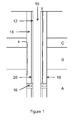
- Figure 1 shows a schematic view of a wells of the type used in the oil and gas industry.
- a well 10 When constructing such wells" it is common to line the well 10 with a steel casing 12 that is secured in place with a sheath of cement 14.
- the cement serves not only to support the casing 12, but to provide hydraulic isolation between the various underground zones A, B, C through which the well has been drilled. Oil or gas from zone A is allowed to enter the casing through perforations 16 formed in the casing 12 and cement 14 and flow back to the surface.
- the presence of the cement 14 prevents flow of fluids x, y outside the casing 12, either back to the surface or into other zones A, B, which can include aquifers or the like.
- Loss of hydraulic isolation may be caused by primary cement failure (for example at the cement-formation interface 18, or cement-casing interface 20) or another such event. This may lead to the leaking of wellbore or formation fluids into surrounding zones.
- formation fluids are sampled using a tool that can be lowered into the well to drill a hole through casing and cement so that fluid can flow from the formation to the tool. Once the sample has been retrieved, the hole in the casing is plugged to maintain hydraulic isolation.
- a tool is the CHDT of Schlumberger (see also US5687806 ).
- This invention seeks to overcome problems associated with current squeeze cementing operations by providing a through casing technique for placing remediation fluids that does not require the complex setup of current techniques.
- a first aspect of the invention provides an apparatus for performing remedial zonal isolation in a well having a casing surrounded by a cement layer, the apparatus comprising a tool body that can be positioned in the well adjacent a region to be treated, the tool body including;
- the apparatus preferably further comprises an orientation system for orienting the tool body to a predetermined azimuthal position.
- the drilling system, pumping system and plugging system can be operable more than once for any given trip in the well.
- the apparatus can also comprise a telemetry system for providing data communication between the tool body and a control system at the well surface.
- the measurement system preferably comprises one or more acoustic and/or nuclear measurement systems.
- a conveyance system comprising drill pipe, coiled tubing or a wireline cable can also be provided, and the tool body can further comprise an anchoring system for securing the tool body in place while remedial operations are performed.
- a second aspect of the invention provides a method of performing remedial zonal isolation in a well having a casing surrounded by a cement layer, the method comprising:
- a preferred embodiment of method further comprises re-evaluating the cement layer after the remediation fluids have been pumped and the hole plugged to determine if zonal isolation has been restored to the location.
- the tool body can be repositioned and the steps of drilling, pumping and plugging are repeated at a new location.
- the step of repositioning typically involves reorienting the tool body to a new azimuthal position.
- the steps of positioning, evaluating, drilling, pumping and plugging can be repeated at a number of locations in the same well.
- Figure 1 is a schematic view of a well having a cemented casing
- Figure 2 shows an apparatus according to an embodiment of the invention, comprising a tool body 22 which can be suspended in a borehole on a suitable conveyance system 24.
- the conveyance system is a wireline cable, although coiled tubing or drill pipe could equally be used.
- the tool body 22 comprises a sensor section 26; a main body section 28 including a drilling and plugging mechanism 30 and anchoring pistons 32; an upper body section 34 incoporating a supply of remediation fluids (e.g. a cementing composition) that is connected through to the main body 36; and an orientation head and electronics section 38 that connects to the wireline cable 24 and is operable to rotate the tool to a predetermined azimuthal orientation.
- remediation fluids e.g. a cementing composition
- the sensor section includes one or more sensor systems for evaluating the cement behind casing to identify loss of hydralulic isolation due to cement failure.
- sensors include acoustic (particularly ultrasonic) sensors or nuclear sensors. Such sensors and measurement techinques are well-known.
- FIG. 3 shows more detail of the main body section 28 with the tool deployed in a casing 12.
- the main tool body 28 includes the drilling and plugging mechanisms. These are essentially similar to those of the CHDT discussed above.
- the drilling mechanism includes a drill bit 40 mounted on a flexible drill shaft 42. Two drilling motors are provided, one 44 for rotating the drill shaft 42 and the other 46 for translating (advancing or retracting) the drill shaft 42.
- the plugging mechanism comprises a plug setting piston 48 and a plug magazine 50 carrying a number of plugs and mounted on a spring.
- a flow line 52 connects to the fluid supply in the upper body section 34.
- the drilling mechanism, plugging mechanism and flow line are all mounted in an inner housing 54 which can be translated relative to the main body 28 by means of a piston 56 so that the drill bit 40, flow line 52 or plug 50 can be positioned opposite an opening 58 in the tool body 28.
- the tool In use, the tool is lowered into a well where a loss of hydraulic isolation has been generally identified.
- the sensors are operated to identify the particular location where loss of isolation is believed to occur.
- Data is conveyed back to an operating system at the surface using conventional telemetry techniques to allow an operator to define a suitable location for the remdiation to take place. Once this location is identified, the tool is oriented in the appropriate direction by operation of the orienting head and the anchoring pistons deployed to secure the tool body in place in the well.
- the inner housing 54 is then moved so that the drill bit 40 is adjacent the opening 58 and the motors 44, 46 operated to drill a hole through the casing 12 and into the cement 14. Once the hole is deep enough, the bit is withdrawn back into the tool and the inner body moved until the flow line 50 is adjacent the opening 58. At this point, a seal is established between the tool and casing, then cement or other remediation fluid can be pumped into the hole so as to fill any cracks or openings in the cement 14 causing the loss of zonal isolation. When pumping is finished, the inner housing is again moved and the plug piston operated to plug the hole in the casing.
- the anchor pistons are then retracted and the tool passed past the remediation zone and the measurements repeated to determine whether or not the procedure has restored hydraulic isolation. If it has, a signal is sent to the operating systme and the tool can be retrieved. If not, the tool can be relocated to the treatment zone and reoriented to a different azimuth, the anchor pistons reset, and the process repeated until a satisfactory fluid placement has been achieved.
- This process can be repeated as often as necessary until isolation is restored.
- the remediation fluid can be a hydraulic cement, a resin fluid or other such fluid for sealing the cement.
- the data from the sensors can be used to reconstruct an image of the cement in the zone for remediation to help identify the appropriate location for placement of the fluid.
- the tool can be used to transmit a signal throug the casing to cause the remediation fluid to set.
- the tool can also include sensors for evauation purposes, e.g measuring zonal isolation or cement properties.
Landscapes
- Engineering & Computer Science (AREA)
- Life Sciences & Earth Sciences (AREA)
- Geology (AREA)
- Mining & Mineral Resources (AREA)
- Physics & Mathematics (AREA)
- Environmental & Geological Engineering (AREA)
- Fluid Mechanics (AREA)
- General Life Sciences & Earth Sciences (AREA)
- Geochemistry & Mineralogy (AREA)
- Quality & Reliability (AREA)
- Geophysics (AREA)
- Earth Drilling (AREA)
Priority Applications (2)
| Application Number | Priority Date | Filing Date | Title |
|---|---|---|---|
| EP08167441A EP2180137A1 (fr) | 2008-10-23 | 2008-10-23 | Appareil et procédé pour l'isolation zonale curative via une enveloppe |
| PCT/EP2009/007063 WO2010046020A1 (fr) | 2008-10-23 | 2009-09-30 | Dispositif et procédé d'isolation zonale correctrice pour un tubage percé |
Applications Claiming Priority (1)
| Application Number | Priority Date | Filing Date | Title |
|---|---|---|---|
| EP08167441A EP2180137A1 (fr) | 2008-10-23 | 2008-10-23 | Appareil et procédé pour l'isolation zonale curative via une enveloppe |
Publications (1)
| Publication Number | Publication Date |
|---|---|
| EP2180137A1 true EP2180137A1 (fr) | 2010-04-28 |
Family
ID=40394272
Family Applications (1)
| Application Number | Title | Priority Date | Filing Date |
|---|---|---|---|
| EP08167441A Withdrawn EP2180137A1 (fr) | 2008-10-23 | 2008-10-23 | Appareil et procédé pour l'isolation zonale curative via une enveloppe |
Country Status (2)
| Country | Link |
|---|---|
| EP (1) | EP2180137A1 (fr) |
| WO (1) | WO2010046020A1 (fr) |
Citations (7)
| Publication number | Priority date | Publication date | Assignee | Title |
|---|---|---|---|---|
| US2381929A (en) * | 1940-09-06 | 1945-08-14 | Schlumberger Marcel | Well conditioning apparatus |
| US4074756A (en) * | 1977-01-17 | 1978-02-21 | Exxon Production Research Company | Apparatus and method for well repair operations |
| US4658916A (en) * | 1985-09-13 | 1987-04-21 | Les Bond | Method and apparatus for hydrocarbon recovery |
| US5353873A (en) * | 1993-07-09 | 1994-10-11 | Cooke Jr Claude E | Apparatus for determining mechanical integrity of wells |
| US5687806A (en) | 1996-02-20 | 1997-11-18 | Gas Research Institute | Method and apparatus for drilling with a flexible shaft while using hydraulic assistance |
| EP0984135A2 (fr) * | 1998-08-18 | 2000-03-08 | Schlumberger Holdings Limited | Mesure de pression d'une formation avec capteurs à distance dans des puits cuvelés |
| EP1653043A1 (fr) * | 2004-11-02 | 2006-05-03 | Services Petroliers Schlumberger | Appareil et procédé de traitement de puits de pétrole |
-
2008
- 2008-10-23 EP EP08167441A patent/EP2180137A1/fr not_active Withdrawn
-
2009
- 2009-09-30 WO PCT/EP2009/007063 patent/WO2010046020A1/fr not_active Ceased
Patent Citations (7)
| Publication number | Priority date | Publication date | Assignee | Title |
|---|---|---|---|---|
| US2381929A (en) * | 1940-09-06 | 1945-08-14 | Schlumberger Marcel | Well conditioning apparatus |
| US4074756A (en) * | 1977-01-17 | 1978-02-21 | Exxon Production Research Company | Apparatus and method for well repair operations |
| US4658916A (en) * | 1985-09-13 | 1987-04-21 | Les Bond | Method and apparatus for hydrocarbon recovery |
| US5353873A (en) * | 1993-07-09 | 1994-10-11 | Cooke Jr Claude E | Apparatus for determining mechanical integrity of wells |
| US5687806A (en) | 1996-02-20 | 1997-11-18 | Gas Research Institute | Method and apparatus for drilling with a flexible shaft while using hydraulic assistance |
| EP0984135A2 (fr) * | 1998-08-18 | 2000-03-08 | Schlumberger Holdings Limited | Mesure de pression d'une formation avec capteurs à distance dans des puits cuvelés |
| EP1653043A1 (fr) * | 2004-11-02 | 2006-05-03 | Services Petroliers Schlumberger | Appareil et procédé de traitement de puits de pétrole |
Also Published As
| Publication number | Publication date |
|---|---|
| WO2010046020A1 (fr) | 2010-04-29 |
Similar Documents
| Publication | Publication Date | Title |
|---|---|---|
| AU2003210744B8 (en) | Well system | |
| CN111742110B (zh) | 膨胀封隔器组件的压力测试 | |
| RU2331753C2 (ru) | Скважинный инструмент | |
| US20190153841A1 (en) | Method of Avoiding Frac Hits During Formation Stimulation | |
| WO2019140287A2 (fr) | Procédé permettant d'éviter les impacts de fracturation pendant une stimulation de formation | |
| US10781650B2 (en) | Downhole tool with multi-stage anchoring | |
| EP2180137A1 (fr) | Appareil et procédé pour l'isolation zonale curative via une enveloppe | |
| US10669840B2 (en) | Downhole system having tubular with signal conductor and method | |
| CA3003162C (fr) | Systeme de fond de trou comprenant un materiel tubulaire avec conducteur de signaux et procede | |
| US10400532B2 (en) | Downhole tool anchoring device | |
| US20190145254A1 (en) | Single packer inlet configurations | |
| WO2011012838A2 (fr) | Appareil de mesure | |
| WO2025136814A1 (fr) | Appareil et procédé d'élimination de gâteau de boue |
Legal Events
| Date | Code | Title | Description |
|---|---|---|---|
| PUAI | Public reference made under article 153(3) epc to a published international application that has entered the european phase |
Free format text: ORIGINAL CODE: 0009012 |
|
| AK | Designated contracting states |
Kind code of ref document: A1 Designated state(s): AT BE BG CH CY CZ DE DK EE ES FI FR GB GR HR HU IE IS IT LI LT LU LV MC MT NL NO PL PT RO SE SI SK TR |
|
| AX | Request for extension of the european patent |
Extension state: AL BA MK RS |
|
| AKY | No designation fees paid | ||
| REG | Reference to a national code |
Ref country code: DE Ref legal event code: 8566 |
|
| STAA | Information on the status of an ep patent application or granted ep patent |
Free format text: STATUS: THE APPLICATION IS DEEMED TO BE WITHDRAWN |
|
| 18D | Application deemed to be withdrawn |
Effective date: 20101029 |