EP2180139A2 - Procédé de production d'hydrocarbure - Google Patents
Procédé de production d'hydrocarbure Download PDFInfo
- Publication number
- EP2180139A2 EP2180139A2 EP09013223A EP09013223A EP2180139A2 EP 2180139 A2 EP2180139 A2 EP 2180139A2 EP 09013223 A EP09013223 A EP 09013223A EP 09013223 A EP09013223 A EP 09013223A EP 2180139 A2 EP2180139 A2 EP 2180139A2
- Authority
- EP
- European Patent Office
- Prior art keywords
- fluid
- injected
- petroleum
- line
- injection
- Prior art date
- Legal status (The legal status is an assumption and is not a legal conclusion. Google has not performed a legal analysis and makes no representation as to the accuracy of the status listed.)
- Withdrawn
Links
Images

Classifications
-
- E—FIXED CONSTRUCTIONS
- E21—EARTH OR ROCK DRILLING; MINING
- E21B—EARTH OR ROCK DRILLING; OBTAINING OIL, GAS, WATER, SOLUBLE OR MELTABLE MATERIALS OR A SLURRY OF MINERALS FROM WELLS
- E21B43/00—Methods or apparatus for obtaining oil, gas, water, soluble or meltable materials or a slurry of minerals from wells
- E21B43/16—Enhanced recovery methods for obtaining hydrocarbons
- E21B43/166—Injecting a gaseous medium; Injecting a gaseous medium and a liquid medium
- E21B43/168—Injecting a gaseous medium
Definitions
- the invention relates to a method for injecting a fluid into a petroleum-containing rock or soil layer by means of a suitable conduit, wherein the conduit is introduced into the rock or earth layer, and the fluid for the purpose of increased production of petroleum from the petroleum-containing Rock or soil layer is injected.
- Petroleum is typically found in oil deposits near and below the surface of the earth. From these deposits, the oil is depending on the depth of the deposit in the open pit, as in the Canadian oil sands fields, but usually in civil engineering or by means of oil rigs, which allow a pumping in the middle of the sea won. Mainly oil is extracted in civil engineering. For this purpose, delivery lines are introduced to the depth of the oil reservoir under the surface of the earth by means of boreholes. About this conveyor line, the oil is extracted from the oil reservoir.
- the funding is essentially carried out in three phases.
- the oil is under the pressure of the burdensome earth layers and the associated associated gas.
- oil can often be pumped by the autogenous pressure in the reservoir without further action.
- the oil can be pumped up with technical aids such as deep pumps.
- the autogenous pressure of the oil reservoir alone is generally insufficient after 10% to 15% of the amount in the deposit to transport the oil to the surface of the earth.
- This phase of primary oil production therefore follows the phase of secondary production.
- the reservoir pressure is increased by the injection of water, steam or gas through, introduced into the soil by means of holes, lines.
- water is usually pumped in at this stage, whereby between 30% and 40% of the oil originally present in the deposit (original oil in place or OOIP) can be conveyed to the earth's surface.
- the remainder remaining increasingly dense and dense oil in the deposit hinders further constant promotion. Further oil can only be extracted from the deposit via special processes for tertiary mineral oil extraction.
- Patent Publication GB 2 379 ⁇ 685 Such a tertiary petroleum production process is described in Patent Publication GB 2 379 ⁇ 685.
- a second conduit for supplying a fluid is introduced into the crude oil deposit parallel to the delivery line of the petroleum.
- a fluid consisting of water, steam, foam or foam, nitrogen and / or carbon dioxide is pressed into the oil reservoir.
- water or an aqueous solution or foam is preferably used.
- the line for the injection of the fluid consists after the in GB 2 379 685
- the prior art disclosed two different sections. Both sections are separated by plugs, commonly called “packers" in the petroleum industry, and can be separately charged with the fluid.
- the fluid is injected into the different regions of the oil reservoir via the two different sections in such a way that the supplied quantity of the fluid varies cyclically and asynchronously.
- the process is described as being particularly suitable for petroleum deposits that occur in geological formations that have fractures or gaps.
- the proportion of water in the conveyed via the delivery line, water-petroleum mixture should be kept below a certain limit.
- the cyclical loading and the fractures and gaps present in the oil reservoir prevent an excessively large amount of water from entering the delivery line.
- the fractures and cracks work like drains, which drain the water from the surrounding layers.
- the injection of the fluid into the oil reservoir is done simply through horizontal holes in the supply line, which over the entire Scope of the line are distributed. The fluid is thus pressed spherically evenly distributed in all spatial directions from the supply line.
- gas is used in a process for tertiary mineral oil production, it usually has to be transported to the source of oil in a complex manner.
- An extreme example here are platforms for oil production in the sea. If carbon dioxide is to be used for tertiary mineral oil production in such oil fields, it must be brought to the oil platform first by ship or by pipeline.
- nitrogen would have to be generated on site, i. a small air separation unit will be installed.
- the present invention is therefore based on the object, a method of the type mentioned input in such a way that the consumption of fluid is minimized.
- the present object is achieved in that the fluid is injected discontinuously into the petroleum-containing rock or earth layer.
- the fluid is discontinuously injected into the petroleum-containing rock or soil layer. That is, according to the invention, the fluid is not injected over the entire duration of the tertiary petroleum production process, but is injected intermittently into the petroleum-containing rock or earth layer only in certain phases or cycles.
- a discontinuous injection is understood to mean that the fluid is injected over a certain predetermined period of time and this period is followed by a phase in which no fluid is injected, which in turn is followed by a phase of fluid injection.
- a discontinuous injection of a gas thus takes place in several regular or irregular pulses or periods. That is, in a discontinuous injection of the fluid according to the invention, no fluid is injected over a certain and predetermined period of time. This period, in which no fluid is injected, may vary in duration, but always significantly more than a few seconds.
- the injection or injection of a fluid is understood as meaning the injection or introduction of the fluid into the petroleum-containing rock or earth layer.
- fluid can be saved in a number of ways.
- fluid is saved because in the time when no fluid is injected, the already injected fluid in the petroleum-containing rock or earth layer expands.
- the expanding fluid thus forms a fluid cushion which drives oil in the direction of the delivery line where it can be conveyed.
- the flow rate of the fluid in the petroleum-containing rock or earth layer increases.
- the oil dissolves from the rock or from the earth and is further promoted with significantly less pressure.
- the fluid can surprisingly also liberate oil from the petroleum-containing rock or soil layer which adheres to water cuticles or high surface area minerals in the petroleum-containing rock or earth layer.
- This fluid mixture which contains the oil dissolved out in this way, can be moved by the next injection and thus reaches a second line, which serves as a delivery line.
- the fluid is directionally injected into the petroleum containing rock or soil layer.
- a significantly higher saving of necessary fluid can be achieved with the same conveying effect.
- the directed injection of the fluid ie targeted injection of the fluid in the direction of the delivery line, the amount of injected fluid is additionally minimized during the injection phase.
- directed injection the fluid entry is no longer in the entire solid angle, but only in a partial area. This minimizes the amount of injected fluid.
- a fluid cushion is formed, which, when directed, drives the crude oil in the direction of the delivery line, where it can be conveyed for days.
- the fluid injection forms a fluid cushion.
- this is set in motion by the following injections.
- this fluid pad can be moved in the direction from the conduit to a second conduit, the second conduit serving as a delivery conduit.
- the fluid is injected in the gaseous state.
- the fluid consists of nitrogen, carbon dioxide and / or gaseous hydrocarbons, more preferably methane.
- gaseous fluids such as nitrogen or carbon dioxide are usually not present in the vicinity of the petroleum-containing rock or earth layers in sufficient quantities. Therefore, these gaseous fluids usually have to be transported over longer distances.
- the gaseous fluid used in each case is expediently selected according to the properties and conditions of the petroleum-containing rock or earth layer.
- Gaseous hydrocarbons mix with the petroleum in the rock or soil layer, thereby reducing the capillary forces that hold the petroleum in the rock or earth layer and thus facilitate transport to the delivery line.
- a similar effect occurs with the use of gaseous carbon dioxide.
- Gaseous carbon dioxide mixes with the petroleum and reduces the viscosity.
- gaseous carbon dioxide also easier transport of petroleum is achieved in the petroleum-containing rock or soil layer.
- Nitrogen is preferably injected with superatmospheric pressure. Nitrogen enters the reservoir and spreads in the intended injection direction as long as the gas pressure remains. In this case, the remaining oil in the pore structure can be desorbed and moved together with the gas through the pore structure. If the injection is interrupted during the non-injection phase, the nitrogen gas can also expand laterally and thus penetrate into pore spaces in which oil still adheres to water cuticles or to minerals with a large internal surface or oil droplets are present in small pores. The thus formed oil-water mixture can be moved by the next injection in the direction of the delivery line.
- gaseous fluid may be appropriate.
- gaseous carbon dioxide is particularly advantageous in this case.
- gaseous nitrogen is particularly advantageous in this case.
- gaseous fluids such as carbon dioxide and liquid fluids such as water are combined.
- carbon dioxide and water are mutually injected, that is, on the injection of carbon dioxide, followed by a phase without fluid injection, which in turn is followed by the injection of water.
- the injected gas causes a better flowability of the oil and the subsequently injected water causes the formation of oil banks in the boundaries of the gas streams, which move more or less with straight boundary lines.
- the fluid is injected in pulses.
- the fluid is expediently injected in regular pulses of predetermined length.
- a pulse is understood to be the time span from which Start until the stop of the injection of the fluid.
- a plurality of pulses of predetermined length are expediently injected successively. There is no fluid injection between the pulses. The speed or the pressure of the fluid during a pulse are approximately constant. It has also proved to be advantageous to inject different fluids in successive pulses. By injecting different fluids in successive pulses, the various mechanisms of action and advantages of the respective fluids can advantageously be easily combined with one another.
- gaseous carbon dioxide can be injected in a first pulse and thus the viscosity of the oil in the petroleum-containing rock or earth layer can be reduced.
- gaseous nitrogen in the following pulse, the petroleum can be driven with now lower viscosity in the direction of the delivery line.
- the time interval between two injection pulses is not shorter than the pulse length, and is preferably the simple to ten times the pulse length.
- the pulsed injection ensures that the fluid cushion is reduced by increasing the pressure during the injection process and then increased again. This effect becomes smaller with shorter pulse lengths. Measurements have shown that too short pulse rates can even have a negative effect. In these cases, the injected fluid substantially exits through the conduit through which the fluid has been injected without propelling oil in the petroleum-rich rock or soil layer toward the production conduit. Therefore, care must be taken to ensure a sufficient pulse duration.
- the time interval between two injection pulses i. the time in which no fluid is injected, must also be sufficiently long.
- the time interval between two injection pulses is not shorter than the pulse length. Measurements have shown that sometimes at shorter times a negative effect occurs, i. the fluid is not pressed by the pulse in the direction of the delivery line. Longer times are possible.
- a time interval between two injection pulses is preferably used, which is the simple to ten times the pulse length.
- the minimum pulse length is the time required for the gas to travel halfway between the line through which the fluid is injected. and the support line.
- the minimum pulse length is the time required for the gas to travel halfway between the line through which the fluid is injected. and the support line.
- the fluid is injected as a directed pressure surge.
- the fluid is injected as a short-term surge directed into the petroleum-containing rock or soil layer. This process is repeated several times, with no fluid being injected between the pressure surges.
- the fluid is injected from more than one line directed, wherein pulse length, pulse interval and / or start of the injection at least one line is different from pulse length, pulse spacing and / or start the injection of at least one other line / are.
- more than one line is used for directional and pulsed injection of fluid streams in the direction of a delivery line, it is expedient to inject both fluid streams at a time offset. It is expedient to wait until the fluid flow which has been injected first has actually come into the range of the second fluid flow. As a result, a displacement of the first fluid flow in the direction of the delivery line is possible. Too early or too late injection of the second fluid stream, the combined fluid stream is conducted past the delivery line. Pulse length, pulse interval and / or time of injections must be chosen so that the entire fluid is injected in the direction of the delivery line.
- the amounts of injected fluids from at least two lines are adjusted so that the injected fluid from a first conduit through the Amount of injected fluid from at least one second line, the direction of the delivery line is deflected.
- the amount of injected fluid from the second conduit is thereby adjusted so that it can deflect the injected fluid from the first conduit in the direction of the delivery line.
- the amount of fluid injected in the second conduit is suitably similar to the magnitude of the amount of injected fluid from the first conduit.
- the ratio of the amounts of injected fluids is between 10: 1 and 1: 1.
- the direction of the induced fluids is expediently set from at least two lines such that the combined fluid flow is directed out of the lines in the direction of the delivery line.
- the present invention has a number of advantages over the prior art.
- the amount of induced fluid can be significantly reduced for an equal delivery rate over the prior art. Fluid is saved since the already-induced fluid propagates in the petroleum-containing rock or soil layer during the phase in which no fluid is induced.
- the velocity of the induced fluid in the petroleum-containing rock or earth layer increases in phases, whereby the petroleum is much better dissolved out of the rock or earth layer than in a continuously flowing at the same speed fluid flow.
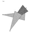
- FIG. 1 shows an embodiment of the method according to the invention, wherein the fluid is injected via the two lines 1 and 2 in the petroleum-containing rock or soil layer. Both lines 1 and 2 are approximately equal to the delivery line. 3 away.
- the gas stream G1 is pulsed injected into the petroleum-containing rock or soil layer.
- the gas stream G2 is also pulsed induced in the petroleum-containing rock or earth layer. Here are pulse lengths of about 20 min. used.
- the time interval between two pulses of an injection line is about 1 hour.
- the injected gas quantities G1 and G2 are each of the same order of magnitude. Due to the superimposition of the directed and pulsed gas flows G1 and G2, a resulting gas flow G3, which moves in the direction of the delivery line 3, is formed.
- the oil is driven in the direction of the delivery line 3 by the directional and pulsed gas streams.
- nitrogen and carbon dioxide are alternately injected, so that the different properties of both gases can be used for crude oil production.
- FIG. 2 shows an embodiment of the invention, wherein the fluid is injected via two lines 1 and 2 in the petroleum-containing rock or earth layer.
- the two lines 1 and 2 spaced at different distances from the feed line 3.
- the pulsed injection of the fluid from line 1 begins before the pulsed injection of the fluid from line 2. That is, the two pulses from line 1 and line 2 are staggered in time.
- the time interval between an injection pulse in line 1 and an injection pulse in line 2 corresponds to the time required for the fluid induced from line 1 to reach line 2 in the injection area of the fluid.
- the fluid is injected via line 1 with a pulse length of three hours.
- the fluid from line 2 is injected with a pulse length of three hours. Subsequently, pulses are injected from both lines with a pulse length of one hour.
- shorter pulse lengths are used, since from the second pulse the fluid cushion in the rock only has to be brought into motion or kept in motion.
- a pulse duration of one hour for injection from line 1 and a pulse duration of 2 hours for injection from line 2 is also possible. If the petroleum-bearing rock or earth layer in the immediate vicinity of line 1 is very porous, a fluid cushion can build up there very quickly. Is the petroleum-containing rock or earth layer in the vicinity of line 2 less porous, longer pulse lengths are used here, since the construction of a fluid cushion also takes longer.
Landscapes
- Life Sciences & Earth Sciences (AREA)
- Engineering & Computer Science (AREA)
- Geology (AREA)
- Mining & Mineral Resources (AREA)
- Physics & Mathematics (AREA)
- Environmental & Geological Engineering (AREA)
- Fluid Mechanics (AREA)
- General Life Sciences & Earth Sciences (AREA)
- Geochemistry & Mineralogy (AREA)
- Physical Or Chemical Processes And Apparatus (AREA)
Applications Claiming Priority (3)
| Application Number | Priority Date | Filing Date | Title |
|---|---|---|---|
| DE102008052465 | 2008-10-21 | ||
| DE102009006572 | 2009-01-29 | ||
| DE102009038445A DE102009038445A1 (de) | 2008-10-21 | 2009-08-21 | Verfahren zur Erdölfeuerung |
Publications (2)
| Publication Number | Publication Date |
|---|---|
| EP2180139A2 true EP2180139A2 (fr) | 2010-04-28 |
| EP2180139A3 EP2180139A3 (fr) | 2011-10-26 |
Family
ID=41484295
Family Applications (1)
| Application Number | Title | Priority Date | Filing Date |
|---|---|---|---|
| EP09013223A Withdrawn EP2180139A3 (fr) | 2008-10-21 | 2009-10-20 | Procédé de production d'hydrocarbure |
Country Status (1)
| Country | Link |
|---|---|
| EP (1) | EP2180139A3 (fr) |
Cited By (1)
| Publication number | Priority date | Publication date | Assignee | Title |
|---|---|---|---|---|
| DE102011105055A1 (de) | 2011-06-20 | 2012-12-20 | Linde Aktiengesellschaft | Verfahren zum Löschen von Bränden in Gesteins- oder Erdschichten, insbesondere in Kohleflözen, oder in Schüttungen, wie Kohleschüttungen |
Family Cites Families (5)
| Publication number | Priority date | Publication date | Assignee | Title |
|---|---|---|---|---|
| US3794114A (en) * | 1952-06-27 | 1974-02-26 | C Brandon | Use of liquefiable gas to control liquid flow in permeable formations |
| DE2550681A1 (de) * | 1974-12-02 | 1976-08-12 | Texaco Development Corp | Verfahren zur gewinnung von kohlenwasserstoffen aus untertaegigen kohlenwasserstoffuehrenden formationen, die sich im wesentlichen in vertikaler richtung erstrecken |
| US5232049A (en) * | 1992-03-27 | 1993-08-03 | Marathon Oil Company | Sequentially flooding a subterranean hydrocarbon-bearing formation with a repeating cycle of immiscible displacement gases |
| US6519531B1 (en) * | 2000-09-27 | 2003-02-11 | Rod P. Batycky | System and methods for visual interpretation of well rate allocation factors |
| GB2379685A (en) * | 2002-10-28 | 2003-03-19 | Shell Internat Res Maatschhapp | Enhanced oil recovery with asynchronous cyclic variation of injection rates |
-
2009
- 2009-10-20 EP EP09013223A patent/EP2180139A3/fr not_active Withdrawn
Cited By (1)
| Publication number | Priority date | Publication date | Assignee | Title |
|---|---|---|---|---|
| DE102011105055A1 (de) | 2011-06-20 | 2012-12-20 | Linde Aktiengesellschaft | Verfahren zum Löschen von Bränden in Gesteins- oder Erdschichten, insbesondere in Kohleflözen, oder in Schüttungen, wie Kohleschüttungen |
Also Published As
| Publication number | Publication date |
|---|---|
| EP2180139A3 (fr) | 2011-10-26 |
Similar Documents
| Publication | Publication Date | Title |
|---|---|---|
| DE4238247C2 (de) | Gewinnung von Kohlenwasserstoffen aus Teersand- oder Schweröllagerstätten | |
| DE2649488C2 (de) | Verfahren zur Gewinnung von Erdöl aus einer unterirdischen Formation | |
| DE69013661T2 (de) | Verfahren und Vorrichtung zur Stimulation einer Untergrundformation durch Injektion eines Fluids aus einer benachbarten Schicht, entlängs von Rissen, ausgehend von einer Bohrung in einer niedrigpermeablen Zwischenschicht. | |
| DE3545550A1 (de) | Bohrlochkomplettierung | |
| DE3046547A1 (de) | Verfahren zur behandlung einer viskose kohlenwasserstoffe enthaltenden formation | |
| DE1280176B (de) | Verfahren zur Gewinnung fluessiger Kohlenwasserstoffe aus einer permeablen, unterirdischen Lagerstaette | |
| DE3047625C2 (de) | Anordnung von Abbaustrecken und Bohrlöchern zur Gewinnung von Erdöl unter Tage durch Einpressen eines Wärmeträgermediums in die erdölführende Schicht | |
| DE3047803A1 (de) | "schachtverfahren fuer den abbau einer erdoelfuehrenden schicht mit sohlenwasser" | |
| DE102009038445A1 (de) | Verfahren zur Erdölfeuerung | |
| DE2454044A1 (de) | Hydraulisches frac-verfahren | |
| DE3030110C2 (de) | Verfahren zur Gewinnung von Erdöl durch Grubenbaue und durch Wärmezufuhr | |
| DE2817657A1 (de) | Verfahren zur gewinnung von erdoel mittels waermeeinwirkung | |
| DE2817658A1 (de) | Verfahren zur gewinnung von erdoel mittels waermeeinwirkung | |
| DE2355870C2 (de) | Wasserdampftrieb-Verfahren zur Erdölgewinnung aus einer einfallenden Erdöl- lagerstätte | |
| DE2011475B2 (de) | Verfahren zum Spülen eines Bohrlochs mittels eines Schaumspülmittels | |
| DE3048179A1 (de) | Verfahren und vorrichtung zur gewinnung von hochviskosem oel aus untergrund-erdformationen | |
| DE1533634A1 (de) | Verfahren zur Gewinnung von Kohlenwasserstoffen aus unterirdischen,kohlenwasserstoffhaltigen Formationen | |
| EP2213832A2 (fr) | Procédé d'injection d'un fluide | |
| DE1902742C2 (de) | Verfahren und Vorrichtung zur Gewinnung von Kalium-Chlorid und Natrium-Chlorid oder Natrium-Chlorid aus naturlichen KCI und NaCI oder NaCI-enthaltenden Lagern | |
| DE2838479A1 (de) | Verfahren zur behandlung einer unterirdischen formation, die eine mit perforationen versehene bohrlochauskleidung umgibt | |
| EP2267269A1 (fr) | Procédé d exploitation de gisements pétroliers dans des formations carbonatées à hétérogénéité élevée des couches en termes de pénétrabilité | |
| DE3000363C2 (de) | Thermisches Gewinnungsverfahren für Erdöl | |
| DE2000642C2 (de) | Verfahren zur Gewinnung von Kalium-Chlorid, Magnesium-Chlorid und Natrium-Chlorid aus natürlichen steinsalzarmen bis steinsalzreichen Carnallititen | |
| DE1533634C (de) | Verfahren zur Gewinnung von Kohlenwasserstoffen aus einer unterirdischen, kohlenwasserstoffhaltigen Formation | |
| DE2007466A1 (de) | Verfahren zur Salzgewinnung aus einer unterirdischen Formation |
Legal Events
| Date | Code | Title | Description |
|---|---|---|---|
| PUAI | Public reference made under article 153(3) epc to a published international application that has entered the european phase |
Free format text: ORIGINAL CODE: 0009012 |
|
| AK | Designated contracting states |
Kind code of ref document: A2 Designated state(s): AT BE BG CH CY CZ DE DK EE ES FI FR GB GR HR HU IE IS IT LI LT LU LV MC MK MT NL NO PL PT RO SE SI SK SM TR |
|
| AX | Request for extension of the european patent |
Extension state: AL BA RS |
|
| PUAL | Search report despatched |
Free format text: ORIGINAL CODE: 0009013 |
|
| AK | Designated contracting states |
Kind code of ref document: A3 Designated state(s): AT BE BG CH CY CZ DE DK EE ES FI FR GB GR HR HU IE IS IT LI LT LU LV MC MK MT NL NO PL PT RO SE SI SK SM TR |
|
| AX | Request for extension of the european patent |
Extension state: AL BA RS |
|
| RIC1 | Information provided on ipc code assigned before grant |
Ipc: E21B 43/16 20060101AFI20110922BHEP |
|
| STAA | Information on the status of an ep patent application or granted ep patent |
Free format text: STATUS: THE APPLICATION IS DEEMED TO BE WITHDRAWN |
|
| 18D | Application deemed to be withdrawn |
Effective date: 20120427 |