EP2180162B1 - Éjecteur de turbine à gaz et procédé de fonctionnement - Google Patents
Éjecteur de turbine à gaz et procédé de fonctionnement Download PDFInfo
- Publication number
- EP2180162B1 EP2180162B1 EP09173331.1A EP09173331A EP2180162B1 EP 2180162 B1 EP2180162 B1 EP 2180162B1 EP 09173331 A EP09173331 A EP 09173331A EP 2180162 B1 EP2180162 B1 EP 2180162B1
- Authority
- EP
- European Patent Office
- Prior art keywords
- high pressure
- outlet
- low pressure
- compressed air
- nozzles
- Prior art date
- Legal status (The legal status is an assumption and is not a legal conclusion. Google has not performed a legal analysis and makes no representation as to the accuracy of the status listed.)
- Active
Links
Images


Classifications
-
- F—MECHANICAL ENGINEERING; LIGHTING; HEATING; WEAPONS; BLASTING
- F02—COMBUSTION ENGINES; HOT-GAS OR COMBUSTION-PRODUCT ENGINE PLANTS
- F02C—GAS-TURBINE PLANTS; AIR INTAKES FOR JET-PROPULSION PLANTS; CONTROLLING FUEL SUPPLY IN AIR-BREATHING JET-PROPULSION PLANTS
- F02C6/00—Plural gas-turbine plants; Combinations of gas-turbine plants with other apparatus; Adaptations of gas-turbine plants for special use
- F02C6/04—Gas-turbine plants providing heated or pressurised working fluid for other apparatus, e.g. without mechanical power output
- F02C6/06—Gas-turbine plants providing heated or pressurised working fluid for other apparatus, e.g. without mechanical power output providing compressed gas
- F02C6/08—Gas-turbine plants providing heated or pressurised working fluid for other apparatus, e.g. without mechanical power output providing compressed gas the gas being bled from the gas-turbine compressor
-
- F—MECHANICAL ENGINEERING; LIGHTING; HEATING; WEAPONS; BLASTING
- F01—MACHINES OR ENGINES IN GENERAL; ENGINE PLANTS IN GENERAL; STEAM ENGINES
- F01D—NON-POSITIVE DISPLACEMENT MACHINES OR ENGINES, e.g. STEAM TURBINES
- F01D25/00—Component parts, details, or accessories, not provided for in, or of interest apart from, other groups
- F01D25/08—Cooling; Heating; Heat-insulation
- F01D25/12—Cooling
-
- F—MECHANICAL ENGINEERING; LIGHTING; HEATING; WEAPONS; BLASTING
- F01—MACHINES OR ENGINES IN GENERAL; ENGINE PLANTS IN GENERAL; STEAM ENGINES
- F01D—NON-POSITIVE DISPLACEMENT MACHINES OR ENGINES, e.g. STEAM TURBINES
- F01D9/00—Stators
- F01D9/06—Fluid supply conduits to nozzles or the like
- F01D9/065—Fluid supply or removal conduits traversing the working fluid flow, e.g. for lubrication-, cooling-, or sealing fluids
Definitions
- the subject matter disclosed herein relates to a system for improving the cooling performance of a turbine engine by utilizing an ejector system that increases compressor air entrainment efficiency.
- the axial location, or stage, at which compressed air is diverted from a compressor for cooling a multi-stage turbine in a turbine engine is determined by the pressure required to drive the specific systems to be serviced by that air. Diverting compressed air from the earliest possible stage of a compressor will increase overall turbine efficiency by reducing the amount of compressor work invested in the diverted air, as well as reducing the temperature of the diverted and, thus, the delivered compressed air. Therefore, it is desirable to achieve the system supply pressure from the earliest and lowest pressure stage of the compressor.
- Known systems divert compressed air from plural ports in a multi-stage compressor to provide cooling and/or sealing air to an associated multi-stage turbine. These systems utilize a low pressure extraction flow path for conducting compressed air from a lower pressure, lower temperature stage of the compressor to the turbine and a high pressure extraction flow path for conducting compressed air from a higher pressure, higher temperature stage of the compressor to the turbine.
- a crossover flow path may be used to interconnect the low pressure extraction flow path, and the high pressure extraction flow path. Such a crossover allows selective control of the compressed air delivered to the multi-stage turbine such that a desired pressure and an economic mixture of air are diverted from the compressor.
- the low and high pressure air is combined through the use of an ejector system such as e.g. in US 2003/0046938 which utilizes the momentum of motive flow of the high pressure air through a nozzle to create a suction flow of low pressure air surrounding the nozzle.
- Interlayer shear operates between the high and low pressure air flow streams within the ejector system resulting in entrainment (suction flow) of the low pressure air with the high pressure flow stream. It is therefore desirable to increase the entrainment of low pressure air flow within the high pressure air flow, to improve the efficiency of the ejector system.
- an ejector system for combining a high pressure fluid flow stream with a low pressure fluid flow stream is described.
- a nozzle chamber in communication with a high pressure fluid flow stream has an inlet and an outlet.
- a suction chamber in communication with a low pressure fluid flow stream includes an inlet, an outlet and is configured to receive the outlet of the nozzle chamber.
- the outlet of the nozzle chamber includes multiple nozzles such that the high pressure flow stream exits the nozzle chamber to define multiple flow streams having multiple surface areas for interlayer drag between the multiple high pressure flow streams and the low pressure flow stream in the suction chamber.
- the low pressure fluid flow stream is entrained by the high pressure fluid flow streams.
- a method of combining a high pressure fluid flow stream with a low pressure fluid flow stream from a multistage compressor includes diverting low pressure compressor air through a low pressure extraction circuit and diverting high pressure compressor air through a high pressure extraction circuit.
- the low pressure compressor air is delivered to an inlet of a suction chamber in an ejector assembly.
- the high pressure compressor air is delivered to an inlet of a nozzle chamber having an outlet disposed within the suction chamber and proximate to an outlet thereof.
- the high pressure compressor air is ejected through multiple outlet nozzles to define multiple, high pressure flow streams having multiple surface areas for interlayer drag between the multiple high pressure flow streams to thereby entrain the low pressure compressed air in the suction chamber in an intermediate pressure, compressed air flow stream.
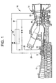
- an extraction system 10 for diverting compressed air from plural ports of a multi-stage compressor 12 to provide cooling and sealing air to an associated multi-stage turbine 14.
- a first casing port 16 is associated with a low pressure stage of the compressor 12 for extracting relatively low pressure, compressed air 18 therefrom.
- a low pressure, first extraction circuit 20 extends from the first casing port 16 to a first target port 22 of the multi-stage turbine 14 for cooling and/or sealing.
- a second casing port 24 is provided downstream from the first casing port 16, and is associated with a higher pressure stage of the compressor for the extraction of relatively high pressure, compressed air 26 therefrom.
- a high pressure, second extraction circuit 28 is provided for flow of the higher pressure compressed air from the second casing port 24 to a second target port 30 of the turbine.
- cooling air which is extracted from multiple ports 16, 24 of a multistage compressor 12 will typically have a pressure differential of at least 16 psi in order to achieve a desirable level of cooling in the multi-stage turbine.
- a cross-over circuit 32 is further provided for selective flow, between the lower pressure, first extraction circuit 20 and the higher pressure, second extraction circuit 28, for selective air flow therebetween.
- an ejector system 34 is disposed in the cross-over circuit 32.
- the ejector system includes a nozzle chamber 35, which receives the high pressure compressed air 26 from second extraction circuit 28 through a motive inlet 36.
- the nozzle chamber is disposed within a suction chamber 42 having a suction inlet 38, which receives lower pressure compressed air 18 from first extraction circuit 20.
- High pressure compressed air 26 exits the nozzle chamber 35 and enters the suction chamber 42, through nozzle outlet 40, FIG.3 .
- Lower pressure compressed air entering suction chamber 42 through suction inlet 38 flows into the suction chamber adjacent to nozzle outlet 40.
- Nozzle outlet 40 comprises an inlet end 44 and an outlet end 46.
- the outlet end of nozzle 40 includes multiple high pressure feed air nozzles 48 through which the high pressure compressed air exits the nozzle chamber 35 and enters suction chamber 42.
- the injection of high pressure compressed air 26 into suction chamber 42 utilizes the momentum of the motive flow of the air to establish a suction flow in the suction chamber 42.
- the use of multiple nozzles 48 increases the surface area for interlayer drag between the high pressure compressed air 26 exiting the nozzle chamber 35 and the lower pressure compressed air 18 in the suction chamber 42, over the surface area defined by a single nozzle ejector. As such, lower pressure compressed air flow entrainment is improved over single nozzle ejectors.
- the number of multiple high pressure feed air nozzles 48 disposed at the outlet end 46 of the nozzle 40 is preferably an odd number such as the three nozzles shown in FIG. 3 .
- the use of an odd number of nozzles defines a non-symmetrical nozzle configuration which has been found to have a preferential effect in lowering the flow induced vibration and acoustical effect arising therefrom. Such acoustics are more likely to occur in symmetrical situations such as in even numbered nozzle configurations.
- Compressed air exiting suction chamber 42 includes a mixture of higher pressure compressed air 26 and lower pressure compressed air 18 which is effectively entrained by the higher pressure compressed air exiting the nozzles 48 of the multi-nozzle 40.
- a high and low pressure compressed air mixture 52 results in an intermediate compressed air pressure and temperature exiting the suction chamber 42.
- the intermediate compressed air 52 enters mixing tube 54 and passes through the diffuser 56 before delivery to the second target port 30 of turbine 14 through discharge outlet 58.
- the increased surface area for interlayer drag between the high and low pressure compressed air 26, 18 flowing through the suction chamber 42 results in the entrainment ratio (the quantity of low pressure air taken up by the motive force of the high pressure air) being increased and, over a broader range of operational conditions. With an improvement in the entrainment of lower pressure air, the efficiency of the turbine system can be increased.
- CFD Computational Fluid Dynamics
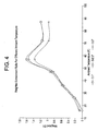
- FIG. 4 one example of an application of the multi-nozzle ejector system of the present invention results in an improved entrainment ratio over single nozzle ejectors in the same application.
- the overall efficiency defined as the integral of weighted entrainment ratio over the ambient temperature range
- a five percent gain in overall efficiency is shown with the multi-nozzle design illustrated in FIG.4 .
- This example is intended to show the performance improvement of the multi-nozzle ejector system over single nozzle systems and the actual percentage gain in overall efficiency is expected to vary based upon the specific application.
- multi-nozzle ejector system of the present invention has been described primarily as it may be applicable to an extraction system 10 for diverting compressed air from a multistage compressor 12 to a multi-stage turbine 14, it is contemplated that the multi-nozzle ejector system has many applications where multiple fluid streams, not limited to air, at differential pressures, likely as low as 2 psi, are combined in an efficient manner.
Landscapes
- Engineering & Computer Science (AREA)
- Mechanical Engineering (AREA)
- General Engineering & Computer Science (AREA)
- Physics & Mathematics (AREA)
- Fluid Mechanics (AREA)
- Chemical & Material Sciences (AREA)
- Combustion & Propulsion (AREA)
- Jet Pumps And Other Pumps (AREA)
Claims (7)
- Système d'éjection (34) pour combiner un courant d'écoulement de fluide haute pression (26) à un courant d'écoulement de fluide basse pression (18), comprenant :une chambre de tuyère (35) en communication avec un courant d'écoulement de fluide haute pression (26) ayant une entrée (36) et une sortie (40) ;une chambre d'aspiration (42) en communication avec un courant d'écoulement de fluide basse pression (18) ayant une entrée (38) et une sortie et configurée pour y recevoir la sortie (40) de la chambre de tuyère (35) ;caractérisé en ce que :la sortie (40) de la chambre de tuyère (35) définit de multiples buses (48), dans lequel le courant d'écoulement haute pression (26) sort de la chambre de tuyère (35) pour définir de multiples courants d'écoulement ayant de multiples aires de surface pour une résistance entre couches entre les multiples courants d'écoulement haute pression et le courant d'écoulement basse pression (18) dans la chambre d'aspiration (42), dans lequel le courant d'écoulement de fluide basse pression (18) est entraîné par les courants d'écoulement de fluide haute pression (26) et dans lequel la sortie (40) de la chambre de tuyère (35) comprend une configuration de tuyère non symétrique.
- Système d'éjection (34) selon la revendication 1, dans lequel la sortie (40) de la chambre de tuyère comprend trois buses (48).
- Système d'éjection (34) selon la revendication 1 ou la revendication 2, dans lequel la sortie (40) de la chambre de tuyère (35) comprend un nombre impair de buses (48).
- Moteur à turbine comprenant :un compresseur à étages multiples (12) et une turbine à étages multiples (14) ;un système d'extraction (10) qui est à même de dévier de l'air comprimé du compresseur à étages multiples (12) à la turbine à étages multiples (14), le système d'extraction comprenant :un premier circuit d'extraction (20) pour dévier de l'air comprimé basse pression (18) et un second circuit d'extraction (28) pour dévier de l'air comprimé haute pression (26) vers la turbine (14) ;un circuit de transition (32) s'étendant entre le premier et le second circuit d'extraction (20, 28) pour un écoulement sélectif entre eux ; etun ensemble d'éjection (34) selon la revendication 1 disposé dans le circuit de transition (32) pour combiner l'air comprimé basse pression (18) et l'air comprimé haute pression (26).
- Moteur à turbine selon la revendication 4, dans lequel la sortie (40) de la chambre de tuyère (35) comprend trois buses (48).
- Moteur à turbine selon la revendication 4 ou 5, dans lequel la sortie (40) de la chambre de tuyère (35) comprend un nombre impair de buses (48).
- Procédé de combinaison d'un courant d'écoulement de fluide haute pression (26) à un courant d'écoulement de fluide basse pression (18) issu d'un compresseur à étages multiples (12) d'un moteur à turbine, comprenant les étapes consistant à :dévier de l'air basse pression du compresseur (18) à travers un circuit d'extraction basse pression (20) et dévier de l'air haute pression du compresseur (26) à travers un circuit d'extraction haute pression (28) ;délivrer l'air de compresseur basse pression (18) à une entrée (38) d'une chambre d'aspiration (42) dans un ensemble d'éjection (34) ;délivrer l'air de compresseur haute pression (26) à une entrée (36) d'une chambre de tuyère (35) ayant un nombre impair de buses de sortie multiples (48) disposées dans la chambre d'aspiration (42) et à proximité de sa sortie ; etéjecter ledit air de compresseur haute pression (26) à travers les multiples buses de sortie (48) pour définir de multiples courants d'écoulement haute pression définis par les multiples buses de sortie (48) ayant des aires de surface multiples pour une résistance entre couches entre les multiples courants d'écoulement haute pression afin d'entraîner de la sorte l'air comprimé basse pression (18) dans la chambre d'aspiration (42) pour définir un courant d'écoulement d'air comprimé à pression intermédiaire (52), dans lequel la configuration des multiples buses de sortie n'est pas symétrique.
Applications Claiming Priority (1)
| Application Number | Priority Date | Filing Date | Title |
|---|---|---|---|
| US12/255,723 US8505310B2 (en) | 2008-10-22 | 2008-10-22 | Gas turbine ejector and method of operation |
Publications (4)
| Publication Number | Publication Date |
|---|---|
| EP2180162A2 EP2180162A2 (fr) | 2010-04-28 |
| EP2180162A3 EP2180162A3 (fr) | 2014-08-20 |
| EP2180162B1 true EP2180162B1 (fr) | 2015-12-23 |
| EP2180162B2 EP2180162B2 (fr) | 2024-02-14 |
Family
ID=41571140
Family Applications (1)
| Application Number | Title | Priority Date | Filing Date |
|---|---|---|---|
| EP09173331.1A Active EP2180162B2 (fr) | 2008-10-22 | 2009-10-16 | Éjecteur de turbine à gaz et procédé de fonctionnement |
Country Status (4)
| Country | Link |
|---|---|
| US (1) | US8505310B2 (fr) |
| EP (1) | EP2180162B2 (fr) |
| JP (1) | JP5883550B2 (fr) |
| CN (1) | CN101813028B (fr) |
Cited By (2)
| Publication number | Priority date | Publication date | Assignee | Title |
|---|---|---|---|---|
| US10753208B2 (en) | 2018-11-30 | 2020-08-25 | General Electric Company | Airfoils including plurality of nozzles and venturi |
| US10815828B2 (en) | 2018-11-30 | 2020-10-27 | General Electric Company | Hot gas path components including plurality of nozzles and venturi |
Families Citing this family (19)
| Publication number | Priority date | Publication date | Assignee | Title |
|---|---|---|---|---|
| US8151885B2 (en) * | 2009-04-20 | 2012-04-10 | Halliburton Energy Services Inc. | Erosion resistant flow connector |
| US9151182B2 (en) * | 2011-04-22 | 2015-10-06 | General Electric Company | System and method for removing heat from a turbomachine |
| BR112014019410A8 (pt) * | 2012-02-07 | 2017-07-11 | Commw Scient Ind Res Org | Dispositivo e método de redução de atrito de um fluxo de fluido viscoso em um duto |
| USD773478S1 (en) | 2013-03-15 | 2016-12-06 | Park Nicollet Institute | Graphical data display screen with graphical user interface |
| US9938855B2 (en) | 2014-01-31 | 2018-04-10 | Pratt & Whitney Canada Corp. | Cooling system and method for supplying a cooling gas flow |
| US9644643B2 (en) | 2014-11-14 | 2017-05-09 | Hamilton Sundstrand Corporation | Aspirator pump with dual high pressure streams |
| JP2016200088A (ja) * | 2015-04-13 | 2016-12-01 | 三菱重工メカトロシステムズ株式会社 | エゼクタ及びこれを有する高空燃焼試験排気設備 |
| US10502137B2 (en) | 2015-10-19 | 2019-12-10 | General Electric Company | Gas turbine with a valve cooling system |
| USD800757S1 (en) * | 2016-07-05 | 2017-10-24 | Park Nicollet Institute | Graphical data display screen with graphical user interface for display of continuous loop insulin and glucose data |
| US10730636B2 (en) | 2016-07-18 | 2020-08-04 | Rolls-Royce North American Technologies Inc. | Integrated aircraft cooling system |
| US10794402B2 (en) | 2017-10-31 | 2020-10-06 | General Electric Company | Ejector and a turbo-machine having an ejector |
| USD939540S1 (en) | 2018-06-04 | 2021-12-28 | Healthpartners Institute | Display screen with graphical user interface |
| USD934884S1 (en) | 2019-05-10 | 2021-11-02 | Healthpartners Institute | Display screen with graphical user interface |
| US11572829B2 (en) | 2020-05-16 | 2023-02-07 | General Electric Company | System and method for combining compressor bleed flow and ventilation flow of gas turbine engine |
| USD1059372S1 (en) | 2021-12-03 | 2025-01-28 | Abbott Diabetes Care Inc. | Display screen or portion thereof with graphical user interface |
| USD1050151S1 (en) | 2021-12-03 | 2024-11-05 | Abbott Diabetes Care Inc. | Display screen or portion thereof with graphical user interface |
| US12234840B2 (en) * | 2022-06-07 | 2025-02-25 | Honeywell International Inc. | Jet pump system |
| USD1082807S1 (en) | 2022-11-22 | 2025-07-08 | Diversified Health Technologies, Llc | Display screen or portion thereof with a graphical user interface |
| USD1113943S1 (en) * | 2022-11-22 | 2026-02-17 | Diversified Health Technologies, Llc | Display screen or portion thereof with a graphical user interface |
Citations (18)
| Publication number | Priority date | Publication date | Assignee | Title |
|---|---|---|---|---|
| US2164263A (en) | 1938-03-25 | 1939-06-27 | John J Wall | Jet air pump |
| US4285466A (en) | 1980-02-25 | 1981-08-25 | The Boeing Co. | Apparatus for mixing high and low pressure air from a jet engine |
| EP0182175B1 (fr) | 1984-11-17 | 1990-05-30 | L. & C. Steinmüller GmbH | Pulvérisateur avec calotte de répartition rapportée pour la réduction de l'émission en oxyde nitrique pendant la combustion de combustibles liquides |
| DE4233058A1 (de) | 1992-10-01 | 1994-04-07 | Horst Dipl Ing Grapenthin | Entspannungs- und Mischdüsen |
| EP0913567A2 (fr) | 1997-10-31 | 1999-05-06 | General Electric Company | Tuyère chevronnée |
| US6412270B1 (en) | 2001-09-12 | 2002-07-02 | General Electric Company | Apparatus and methods for flowing a cooling or purge medium in a turbine downstream of a turbine seal |
| US20030046938A1 (en) | 2001-09-12 | 2003-03-13 | Mortzheim Jason Paul | Apparatus and methods for controlling flow in turbomachinery |
| US20030205049A1 (en) | 2002-05-02 | 2003-11-06 | Honeywell International, Inc. | Variable geometry ejector for a bleed air system using integral ejector exit pressure feedback |
| US7162876B2 (en) | 2003-10-03 | 2007-01-16 | United Technologies Corporation | Ejector for cooling air supply pressure optimization |
| EP1795710A2 (fr) | 2005-12-07 | 2007-06-13 | General Electric Company | Ejecteur avec une tuyère motrice variable pour l'utilisation dans des moteurs de turbine |
| US20070243811A1 (en) | 2006-03-27 | 2007-10-18 | Pratt & Whitney Canada Corp. | Ejector controlled twin air source gas turbine pressurizing air system |
| JP2007285165A (ja) | 2006-04-14 | 2007-11-01 | Hitachi Ltd | ジェットポンプ |
| EP1852614A2 (fr) | 2006-05-04 | 2007-11-07 | General Electric Company | Tuyère propulsive à faible bruit pour éjecteur |
| US7310939B2 (en) | 2003-07-09 | 2007-12-25 | Snecma | Device for reducing the jet noise of a turbomachine |
| DE102006047137A1 (de) | 2006-10-05 | 2008-04-10 | Robert Bosch Gmbh | Lochscheibe, Brennstoffeinspritzventil mit einer Lochscheibe und Verfahren zur Herstellung einer Lochscheibe |
| EP1923553A2 (fr) | 2006-11-16 | 2008-05-21 | Honeywell International, Inc. | Système de purge à ports multiples avec une pompe d'éjecteur à géométrie variable |
| EP1965052A2 (fr) | 2007-02-27 | 2008-09-03 | General Electric Company | Mélangeur pour le système d'air de refroidissement et d'étanchéité d'une turbomachine |
| EP1980717A2 (fr) | 2007-04-04 | 2008-10-15 | General Electric Company | Mélangeur pour le systéme d' air de refroidissement et d' étanchéification de turbomachine |
Family Cites Families (12)
| Publication number | Priority date | Publication date | Assignee | Title |
|---|---|---|---|---|
| US1262102A (en) * | 1914-09-14 | 1918-04-09 | Westinghouse Electric & Mfg Co | Fluid-translating device. |
| US2074480A (en) * | 1936-03-18 | 1937-03-23 | Ingersoll Rand Co | Thermocompressor |
| US2190109A (en) * | 1937-07-09 | 1940-02-13 | George A Ball | Low pressure steam injector |
| US2556899A (en) * | 1947-03-27 | 1951-06-12 | William W Broussard | Gas removing device |
| FR2554874B1 (fr) * | 1983-11-10 | 1988-04-15 | Bertin & Cie | Ejecteur-melangeur a effet de trompe a section variable et application |
| US4847043A (en) * | 1988-01-25 | 1989-07-11 | General Electric Company | Steam-assisted jet pump |
| JPH07119700A (ja) * | 1993-10-21 | 1995-05-09 | Toshiba Corp | ジェットポンプ |
| US6615574B1 (en) * | 2000-01-14 | 2003-09-09 | General Electric Co. | System for combining flow from compressor bleeds of an industrial gas turbine for gas turbine performance optimization |
| WO2002016779A1 (fr) * | 2000-08-18 | 2002-02-28 | Ocean Power Corporation | Ejecteur de vapeur hautement efficace destine a des applications de dessalage |
| US6877960B1 (en) * | 2002-06-05 | 2005-04-12 | Flodesign, Inc. | Lobed convergent/divergent supersonic nozzle ejector system |
| US7076952B1 (en) * | 2005-01-02 | 2006-07-18 | Jan Vetrovec | Supercharged internal combustion engine |
| US8083495B2 (en) * | 2008-08-14 | 2011-12-27 | General Electric Company | Ejectors with separably secured nozzles, adjustable size nozzles, or adjustable size mixing tubes |
-
2008
- 2008-10-22 US US12/255,723 patent/US8505310B2/en active Active
-
2009
- 2009-10-13 JP JP2009235838A patent/JP5883550B2/ja not_active Expired - Fee Related
- 2009-10-16 EP EP09173331.1A patent/EP2180162B2/fr active Active
- 2009-10-22 CN CN200910209824.9A patent/CN101813028B/zh not_active Expired - Fee Related
Patent Citations (18)
| Publication number | Priority date | Publication date | Assignee | Title |
|---|---|---|---|---|
| US2164263A (en) | 1938-03-25 | 1939-06-27 | John J Wall | Jet air pump |
| US4285466A (en) | 1980-02-25 | 1981-08-25 | The Boeing Co. | Apparatus for mixing high and low pressure air from a jet engine |
| EP0182175B1 (fr) | 1984-11-17 | 1990-05-30 | L. & C. Steinmüller GmbH | Pulvérisateur avec calotte de répartition rapportée pour la réduction de l'émission en oxyde nitrique pendant la combustion de combustibles liquides |
| DE4233058A1 (de) | 1992-10-01 | 1994-04-07 | Horst Dipl Ing Grapenthin | Entspannungs- und Mischdüsen |
| EP0913567A2 (fr) | 1997-10-31 | 1999-05-06 | General Electric Company | Tuyère chevronnée |
| US6412270B1 (en) | 2001-09-12 | 2002-07-02 | General Electric Company | Apparatus and methods for flowing a cooling or purge medium in a turbine downstream of a turbine seal |
| US20030046938A1 (en) | 2001-09-12 | 2003-03-13 | Mortzheim Jason Paul | Apparatus and methods for controlling flow in turbomachinery |
| US20030205049A1 (en) | 2002-05-02 | 2003-11-06 | Honeywell International, Inc. | Variable geometry ejector for a bleed air system using integral ejector exit pressure feedback |
| US7310939B2 (en) | 2003-07-09 | 2007-12-25 | Snecma | Device for reducing the jet noise of a turbomachine |
| US7162876B2 (en) | 2003-10-03 | 2007-01-16 | United Technologies Corporation | Ejector for cooling air supply pressure optimization |
| EP1795710A2 (fr) | 2005-12-07 | 2007-06-13 | General Electric Company | Ejecteur avec une tuyère motrice variable pour l'utilisation dans des moteurs de turbine |
| US20070243811A1 (en) | 2006-03-27 | 2007-10-18 | Pratt & Whitney Canada Corp. | Ejector controlled twin air source gas turbine pressurizing air system |
| JP2007285165A (ja) | 2006-04-14 | 2007-11-01 | Hitachi Ltd | ジェットポンプ |
| EP1852614A2 (fr) | 2006-05-04 | 2007-11-07 | General Electric Company | Tuyère propulsive à faible bruit pour éjecteur |
| DE102006047137A1 (de) | 2006-10-05 | 2008-04-10 | Robert Bosch Gmbh | Lochscheibe, Brennstoffeinspritzventil mit einer Lochscheibe und Verfahren zur Herstellung einer Lochscheibe |
| EP1923553A2 (fr) | 2006-11-16 | 2008-05-21 | Honeywell International, Inc. | Système de purge à ports multiples avec une pompe d'éjecteur à géométrie variable |
| EP1965052A2 (fr) | 2007-02-27 | 2008-09-03 | General Electric Company | Mélangeur pour le système d'air de refroidissement et d'étanchéité d'une turbomachine |
| EP1980717A2 (fr) | 2007-04-04 | 2008-10-15 | General Electric Company | Mélangeur pour le systéme d' air de refroidissement et d' étanchéification de turbomachine |
Cited By (2)
| Publication number | Priority date | Publication date | Assignee | Title |
|---|---|---|---|---|
| US10753208B2 (en) | 2018-11-30 | 2020-08-25 | General Electric Company | Airfoils including plurality of nozzles and venturi |
| US10815828B2 (en) | 2018-11-30 | 2020-10-27 | General Electric Company | Hot gas path components including plurality of nozzles and venturi |
Also Published As
| Publication number | Publication date |
|---|---|
| JP2010101315A (ja) | 2010-05-06 |
| US20100096474A1 (en) | 2010-04-22 |
| CN101813028B (zh) | 2015-07-22 |
| EP2180162A2 (fr) | 2010-04-28 |
| EP2180162B2 (fr) | 2024-02-14 |
| US8505310B2 (en) | 2013-08-13 |
| EP2180162A3 (fr) | 2014-08-20 |
| JP5883550B2 (ja) | 2016-03-15 |
| CN101813028A (zh) | 2010-08-25 |
Similar Documents
| Publication | Publication Date | Title |
|---|---|---|
| EP2180162B2 (fr) | Éjecteur de turbine à gaz et procédé de fonctionnement | |
| US7823390B2 (en) | Mixer for cooling and sealing air system of turbomachinery | |
| US6550253B2 (en) | Apparatus and methods for controlling flow in turbomachinery | |
| CN105073219B (zh) | 带有喷射增强撞击的气油分离器及其相关方法 | |
| JP5555284B2 (ja) | 可変動力ノズルエジェクタを含むタービンシステム及び圧縮機抽気を最大限に生かす方法 | |
| US20170074172A1 (en) | Ejector based external bleed system for a gas turbine engine | |
| CN102203435B (zh) | 超音速喷射器成套设备 | |
| US11261793B2 (en) | Engine fuel system for use with composite aircraft | |
| CN102435017A (zh) | 一种采用多效复叠引射方式的喷射式热泵及大压比真空泵 | |
| EP2944827B1 (fr) | Arrangement éjecteur | |
| EP3599344A1 (fr) | Systèmes de séparation de particules de moteur à turbine | |
| US20190128289A1 (en) | Ejector and a turbo-machine having an ejector | |
| CN112746985A (zh) | 引射结构、压缩机组件以及具有其的制冷设备 | |
| EP2299125A3 (fr) | Ensemble de pompe à jet doté d'un débit d'entraînement amélioré | |
| CN215409379U (zh) | 引射结构、压缩机组件以及具有其的制冷设备 | |
| CN108884839B (zh) | 喷射器、喷射器的制造方法以及扩散器的出口流路的设定方法 | |
| CN219210325U (zh) | 一种喷射器 | |
| EP4614066A1 (fr) | Vanne bistable | |
| RU2133884C1 (ru) | Жидкостно-газовый эжектор (варианты) | |
| JPS60501166A (ja) | 燃料系統消泡装置 | |
| CN120712416A (zh) | 通过注水来提高压力比的氢气离心式压缩机系统及其操作方法 | |
| WO2026101537A1 (fr) | Appareil d'accélérateur de fluide |
Legal Events
| Date | Code | Title | Description |
|---|---|---|---|
| PUAI | Public reference made under article 153(3) epc to a published international application that has entered the european phase |
Free format text: ORIGINAL CODE: 0009012 |
|
| AK | Designated contracting states |
Kind code of ref document: A2 Designated state(s): AT BE BG CH CY CZ DE DK EE ES FI FR GB GR HR HU IE IS IT LI LT LU LV MC MK MT NL NO PL PT RO SE SI SK SM TR |
|
| PUAL | Search report despatched |
Free format text: ORIGINAL CODE: 0009013 |
|
| AK | Designated contracting states |
Kind code of ref document: A3 Designated state(s): AT BE BG CH CY CZ DE DK EE ES FI FR GB GR HR HU IE IS IT LI LT LU LV MC MK MT NL NO PL PT RO SE SI SK SM TR |
|
| RIC1 | Information provided on ipc code assigned before grant |
Ipc: F01D 25/12 20060101ALI20140711BHEP Ipc: F01D 9/06 20060101ALI20140711BHEP Ipc: F02C 6/08 20060101AFI20140711BHEP |
|
| 17P | Request for examination filed |
Effective date: 20150220 |
|
| RBV | Designated contracting states (corrected) |
Designated state(s): AT BE BG CH CY CZ DE DK EE ES FI FR GB GR HR HU IE IS IT LI LT LU LV MC MK MT NL NO PL PT RO SE SI SK SM TR |
|
| GRAP | Despatch of communication of intention to grant a patent |
Free format text: ORIGINAL CODE: EPIDOSNIGR1 |
|
| INTG | Intention to grant announced |
Effective date: 20150703 |
|
| GRAS | Grant fee paid |
Free format text: ORIGINAL CODE: EPIDOSNIGR3 |
|
| GRAA | (expected) grant |
Free format text: ORIGINAL CODE: 0009210 |
|
| AK | Designated contracting states |
Kind code of ref document: B1 Designated state(s): AT BE BG CH CY CZ DE DK EE ES FI FR GB GR HR HU IE IS IT LI LT LU LV MC MK MT NL NO PL PT RO SE SI SK SM TR |
|
| REG | Reference to a national code |
Ref country code: GB Ref legal event code: FG4D |
|
| REG | Reference to a national code |
Ref country code: CH Ref legal event code: EP |
|
| REG | Reference to a national code |
Ref country code: IE Ref legal event code: FG4D |
|
| REG | Reference to a national code |
Ref country code: AT Ref legal event code: REF Ref document number: 766679 Country of ref document: AT Kind code of ref document: T Effective date: 20160115 |
|
| REG | Reference to a national code |
Ref country code: DE Ref legal event code: R096 Ref document number: 602009035353 Country of ref document: DE |
|
| REG | Reference to a national code |
Ref country code: LT Ref legal event code: MG4D |
|
| REG | Reference to a national code |
Ref country code: NL Ref legal event code: MP Effective date: 20151223 |
|
| PG25 | Lapsed in a contracting state [announced via postgrant information from national office to epo] |
Ref country code: LT Free format text: LAPSE BECAUSE OF FAILURE TO SUBMIT A TRANSLATION OF THE DESCRIPTION OR TO PAY THE FEE WITHIN THE PRESCRIBED TIME-LIMIT Effective date: 20151223 Ref country code: NO Free format text: LAPSE BECAUSE OF FAILURE TO SUBMIT A TRANSLATION OF THE DESCRIPTION OR TO PAY THE FEE WITHIN THE PRESCRIBED TIME-LIMIT Effective date: 20160323 Ref country code: HR Free format text: LAPSE BECAUSE OF FAILURE TO SUBMIT A TRANSLATION OF THE DESCRIPTION OR TO PAY THE FEE WITHIN THE PRESCRIBED TIME-LIMIT Effective date: 20151223 |
|
| REG | Reference to a national code |
Ref country code: AT Ref legal event code: MK05 Ref document number: 766679 Country of ref document: AT Kind code of ref document: T Effective date: 20151223 |
|
| PG25 | Lapsed in a contracting state [announced via postgrant information from national office to epo] |
Ref country code: NL Free format text: LAPSE BECAUSE OF FAILURE TO SUBMIT A TRANSLATION OF THE DESCRIPTION OR TO PAY THE FEE WITHIN THE PRESCRIBED TIME-LIMIT Effective date: 20151223 Ref country code: GR Free format text: LAPSE BECAUSE OF FAILURE TO SUBMIT A TRANSLATION OF THE DESCRIPTION OR TO PAY THE FEE WITHIN THE PRESCRIBED TIME-LIMIT Effective date: 20160324 Ref country code: FI Free format text: LAPSE BECAUSE OF FAILURE TO SUBMIT A TRANSLATION OF THE DESCRIPTION OR TO PAY THE FEE WITHIN THE PRESCRIBED TIME-LIMIT Effective date: 20151223 Ref country code: SE Free format text: LAPSE BECAUSE OF FAILURE TO SUBMIT A TRANSLATION OF THE DESCRIPTION OR TO PAY THE FEE WITHIN THE PRESCRIBED TIME-LIMIT Effective date: 20151223 Ref country code: LV Free format text: LAPSE BECAUSE OF FAILURE TO SUBMIT A TRANSLATION OF THE DESCRIPTION OR TO PAY THE FEE WITHIN THE PRESCRIBED TIME-LIMIT Effective date: 20151223 |
|
| PG25 | Lapsed in a contracting state [announced via postgrant information from national office to epo] |
Ref country code: ES Free format text: LAPSE BECAUSE OF FAILURE TO SUBMIT A TRANSLATION OF THE DESCRIPTION OR TO PAY THE FEE WITHIN THE PRESCRIBED TIME-LIMIT Effective date: 20151223 Ref country code: CZ Free format text: LAPSE BECAUSE OF FAILURE TO SUBMIT A TRANSLATION OF THE DESCRIPTION OR TO PAY THE FEE WITHIN THE PRESCRIBED TIME-LIMIT Effective date: 20151223 Ref country code: IT Free format text: LAPSE BECAUSE OF FAILURE TO SUBMIT A TRANSLATION OF THE DESCRIPTION OR TO PAY THE FEE WITHIN THE PRESCRIBED TIME-LIMIT Effective date: 20151223 |
|
| PG25 | Lapsed in a contracting state [announced via postgrant information from national office to epo] |
Ref country code: AT Free format text: LAPSE BECAUSE OF FAILURE TO SUBMIT A TRANSLATION OF THE DESCRIPTION OR TO PAY THE FEE WITHIN THE PRESCRIBED TIME-LIMIT Effective date: 20151223 Ref country code: RO Free format text: LAPSE BECAUSE OF FAILURE TO SUBMIT A TRANSLATION OF THE DESCRIPTION OR TO PAY THE FEE WITHIN THE PRESCRIBED TIME-LIMIT Effective date: 20151223 Ref country code: SM Free format text: LAPSE BECAUSE OF FAILURE TO SUBMIT A TRANSLATION OF THE DESCRIPTION OR TO PAY THE FEE WITHIN THE PRESCRIBED TIME-LIMIT Effective date: 20151223 Ref country code: PT Free format text: LAPSE BECAUSE OF FAILURE TO SUBMIT A TRANSLATION OF THE DESCRIPTION OR TO PAY THE FEE WITHIN THE PRESCRIBED TIME-LIMIT Effective date: 20160426 Ref country code: IS Free format text: LAPSE BECAUSE OF FAILURE TO SUBMIT A TRANSLATION OF THE DESCRIPTION OR TO PAY THE FEE WITHIN THE PRESCRIBED TIME-LIMIT Effective date: 20160423 Ref country code: PL Free format text: LAPSE BECAUSE OF FAILURE TO SUBMIT A TRANSLATION OF THE DESCRIPTION OR TO PAY THE FEE WITHIN THE PRESCRIBED TIME-LIMIT Effective date: 20151223 Ref country code: SK Free format text: LAPSE BECAUSE OF FAILURE TO SUBMIT A TRANSLATION OF THE DESCRIPTION OR TO PAY THE FEE WITHIN THE PRESCRIBED TIME-LIMIT Effective date: 20151223 Ref country code: EE Free format text: LAPSE BECAUSE OF FAILURE TO SUBMIT A TRANSLATION OF THE DESCRIPTION OR TO PAY THE FEE WITHIN THE PRESCRIBED TIME-LIMIT Effective date: 20151223 |
|
| REG | Reference to a national code |
Ref country code: DE Ref legal event code: R026 Ref document number: 602009035353 Country of ref document: DE |
|
| PLBI | Opposition filed |
Free format text: ORIGINAL CODE: 0009260 |
|
| 26 | Opposition filed |
Opponent name: SIEMENS AKTIENGESELLSCHAFT Effective date: 20160921 |
|
| PG25 | Lapsed in a contracting state [announced via postgrant information from national office to epo] |
Ref country code: DK Free format text: LAPSE BECAUSE OF FAILURE TO SUBMIT A TRANSLATION OF THE DESCRIPTION OR TO PAY THE FEE WITHIN THE PRESCRIBED TIME-LIMIT Effective date: 20151223 |
|
| PLAX | Notice of opposition and request to file observation + time limit sent |
Free format text: ORIGINAL CODE: EPIDOSNOBS2 |
|
| PG25 | Lapsed in a contracting state [announced via postgrant information from national office to epo] |
Ref country code: BE Free format text: LAPSE BECAUSE OF FAILURE TO SUBMIT A TRANSLATION OF THE DESCRIPTION OR TO PAY THE FEE WITHIN THE PRESCRIBED TIME-LIMIT Effective date: 20151223 |
|
| PG25 | Lapsed in a contracting state [announced via postgrant information from national office to epo] |
Ref country code: SI Free format text: LAPSE BECAUSE OF FAILURE TO SUBMIT A TRANSLATION OF THE DESCRIPTION OR TO PAY THE FEE WITHIN THE PRESCRIBED TIME-LIMIT Effective date: 20151223 |
|
| PLBB | Reply of patent proprietor to notice(s) of opposition received |
Free format text: ORIGINAL CODE: EPIDOSNOBS3 |
|
| REG | Reference to a national code |
Ref country code: CH Ref legal event code: PL |
|
| GBPC | Gb: european patent ceased through non-payment of renewal fee |
Effective date: 20161016 |
|
| REG | Reference to a national code |
Ref country code: IE Ref legal event code: MM4A |
|
| REG | Reference to a national code |
Ref country code: FR Ref legal event code: ST Effective date: 20170630 |
|
| PG25 | Lapsed in a contracting state [announced via postgrant information from national office to epo] |
Ref country code: FR Free format text: LAPSE BECAUSE OF NON-PAYMENT OF DUE FEES Effective date: 20161102 Ref country code: CH Free format text: LAPSE BECAUSE OF NON-PAYMENT OF DUE FEES Effective date: 20161031 Ref country code: LI Free format text: LAPSE BECAUSE OF NON-PAYMENT OF DUE FEES Effective date: 20161031 Ref country code: GB Free format text: LAPSE BECAUSE OF NON-PAYMENT OF DUE FEES Effective date: 20161016 |
|
| PG25 | Lapsed in a contracting state [announced via postgrant information from national office to epo] |
Ref country code: LU Free format text: LAPSE BECAUSE OF NON-PAYMENT OF DUE FEES Effective date: 20161016 |
|
| PLAB | Opposition data, opponent's data or that of the opponent's representative modified |
Free format text: ORIGINAL CODE: 0009299OPPO |
|
| R26 | Opposition filed (corrected) |
Opponent name: SIEMENS AKTIENGESELLSCHAFT Effective date: 20160921 |
|
| PG25 | Lapsed in a contracting state [announced via postgrant information from national office to epo] |
Ref country code: IE Free format text: LAPSE BECAUSE OF NON-PAYMENT OF DUE FEES Effective date: 20161016 |
|
| RDAF | Communication despatched that patent is revoked |
Free format text: ORIGINAL CODE: EPIDOSNREV1 |
|
| STAA | Information on the status of an ep patent application or granted ep patent |
Free format text: STATUS: THE PATENT HAS BEEN GRANTED |
|
| PG25 | Lapsed in a contracting state [announced via postgrant information from national office to epo] |
Ref country code: HU Free format text: LAPSE BECAUSE OF FAILURE TO SUBMIT A TRANSLATION OF THE DESCRIPTION OR TO PAY THE FEE WITHIN THE PRESCRIBED TIME-LIMIT; INVALID AB INITIO Effective date: 20091016 Ref country code: CY Free format text: LAPSE BECAUSE OF FAILURE TO SUBMIT A TRANSLATION OF THE DESCRIPTION OR TO PAY THE FEE WITHIN THE PRESCRIBED TIME-LIMIT Effective date: 20151223 |
|
| PG25 | Lapsed in a contracting state [announced via postgrant information from national office to epo] |
Ref country code: MT Free format text: LAPSE BECAUSE OF NON-PAYMENT OF DUE FEES Effective date: 20161031 Ref country code: MK Free format text: LAPSE BECAUSE OF FAILURE TO SUBMIT A TRANSLATION OF THE DESCRIPTION OR TO PAY THE FEE WITHIN THE PRESCRIBED TIME-LIMIT Effective date: 20151223 Ref country code: TR Free format text: LAPSE BECAUSE OF FAILURE TO SUBMIT A TRANSLATION OF THE DESCRIPTION OR TO PAY THE FEE WITHIN THE PRESCRIBED TIME-LIMIT Effective date: 20151223 Ref country code: MC Free format text: LAPSE BECAUSE OF FAILURE TO SUBMIT A TRANSLATION OF THE DESCRIPTION OR TO PAY THE FEE WITHIN THE PRESCRIBED TIME-LIMIT Effective date: 20151223 |
|
| APAH | Appeal reference modified |
Free format text: ORIGINAL CODE: EPIDOSCREFNO |
|
| APBM | Appeal reference recorded |
Free format text: ORIGINAL CODE: EPIDOSNREFNO |
|
| APBP | Date of receipt of notice of appeal recorded |
Free format text: ORIGINAL CODE: EPIDOSNNOA2O |
|
| PG25 | Lapsed in a contracting state [announced via postgrant information from national office to epo] |
Ref country code: BG Free format text: LAPSE BECAUSE OF FAILURE TO SUBMIT A TRANSLATION OF THE DESCRIPTION OR TO PAY THE FEE WITHIN THE PRESCRIBED TIME-LIMIT Effective date: 20151223 |
|
| APBQ | Date of receipt of statement of grounds of appeal recorded |
Free format text: ORIGINAL CODE: EPIDOSNNOA3O |
|
| PLAB | Opposition data, opponent's data or that of the opponent's representative modified |
Free format text: ORIGINAL CODE: 0009299OPPO |
|
| R26 | Opposition filed (corrected) |
Opponent name: SIEMENS AKTIENGESELLSCHAFT Effective date: 20160921 |
|
| APBU | Appeal procedure closed |
Free format text: ORIGINAL CODE: EPIDOSNNOA9O |
|
| PLAY | Examination report in opposition despatched + time limit |
Free format text: ORIGINAL CODE: EPIDOSNORE2 |
|
| PLBC | Reply to examination report in opposition received |
Free format text: ORIGINAL CODE: EPIDOSNORE3 |
|
| P01 | Opt-out of the competence of the unified patent court (upc) registered |
Effective date: 20230522 |
|
| REG | Reference to a national code |
Ref country code: DE Ref legal event code: R081 Ref document number: 602009035353 Country of ref document: DE Owner name: GENERAL ELECTRIC TECHNOLOGY GMBH, CH Free format text: FORMER OWNER: GENERAL ELECTRIC COMPANY, SCHENECTADY, NY, US |
|
| PUAH | Patent maintained in amended form |
Free format text: ORIGINAL CODE: 0009272 |
|
| STAA | Information on the status of an ep patent application or granted ep patent |
Free format text: STATUS: PATENT MAINTAINED AS AMENDED |
|
| 27A | Patent maintained in amended form |
Effective date: 20240214 |
|
| AK | Designated contracting states |
Kind code of ref document: B2 Designated state(s): AT BE BG CH CY CZ DE DK EE ES FI FR GB GR HR HU IE IS IT LI LT LU LV MC MK MT NL NO PL PT RO SE SI SK SM TR |
|
| REG | Reference to a national code |
Ref country code: DE Ref legal event code: R102 Ref document number: 602009035353 Country of ref document: DE |
|
| PGFP | Annual fee paid to national office [announced via postgrant information from national office to epo] |
Ref country code: DE Payment date: 20250923 Year of fee payment: 17 |