EP2180163B1 - Boîtier de turbines et son procédé de fabrication - Google Patents
Boîtier de turbines et son procédé de fabrication Download PDFInfo
- Publication number
- EP2180163B1 EP2180163B1 EP09012735.8A EP09012735A EP2180163B1 EP 2180163 B1 EP2180163 B1 EP 2180163B1 EP 09012735 A EP09012735 A EP 09012735A EP 2180163 B1 EP2180163 B1 EP 2180163B1
- Authority
- EP
- European Patent Office
- Prior art keywords
- sealing ring
- connecting port
- outlet pipe
- turbine housing
- housing
- Prior art date
- Legal status (The legal status is an assumption and is not a legal conclusion. Google has not performed a legal analysis and makes no representation as to the accuracy of the status listed.)
- Not-in-force
Links
Images

Classifications
-
- F—MECHANICAL ENGINEERING; LIGHTING; HEATING; WEAPONS; BLASTING
- F01—MACHINES OR ENGINES IN GENERAL; ENGINE PLANTS IN GENERAL; STEAM ENGINES
- F01D—NON-POSITIVE DISPLACEMENT MACHINES OR ENGINES, e.g. STEAM TURBINES
- F01D11/00—Preventing or minimising internal leakage of working-fluid, e.g. between stages
- F01D11/02—Preventing or minimising internal leakage of working-fluid, e.g. between stages by non-contact sealings, e.g. of labyrinth type
-
- F—MECHANICAL ENGINEERING; LIGHTING; HEATING; WEAPONS; BLASTING
- F01—MACHINES OR ENGINES IN GENERAL; ENGINE PLANTS IN GENERAL; STEAM ENGINES
- F01D—NON-POSITIVE DISPLACEMENT MACHINES OR ENGINES, e.g. STEAM TURBINES
- F01D11/00—Preventing or minimising internal leakage of working-fluid, e.g. between stages
- F01D11/005—Sealing means between non relatively rotating elements
-
- F—MECHANICAL ENGINEERING; LIGHTING; HEATING; WEAPONS; BLASTING
- F01—MACHINES OR ENGINES IN GENERAL; ENGINE PLANTS IN GENERAL; STEAM ENGINES
- F01D—NON-POSITIVE DISPLACEMENT MACHINES OR ENGINES, e.g. STEAM TURBINES
- F01D25/00—Component parts, details, or accessories, not provided for in, or of interest apart from, other groups
- F01D25/24—Casings; Casing parts, e.g. diaphragms, casing fastenings
-
- F—MECHANICAL ENGINEERING; LIGHTING; HEATING; WEAPONS; BLASTING
- F01—MACHINES OR ENGINES IN GENERAL; ENGINE PLANTS IN GENERAL; STEAM ENGINES
- F01D—NON-POSITIVE DISPLACEMENT MACHINES OR ENGINES, e.g. STEAM TURBINES
- F01D9/00—Stators
- F01D9/02—Nozzles; Nozzle boxes; Stator blades; Guide conduits, e.g. individual nozzles
-
- F—MECHANICAL ENGINEERING; LIGHTING; HEATING; WEAPONS; BLASTING
- F02—COMBUSTION ENGINES; HOT-GAS OR COMBUSTION-PRODUCT ENGINE PLANTS
- F02C—GAS-TURBINE PLANTS; AIR INTAKES FOR JET-PROPULSION PLANTS; CONTROLLING FUEL SUPPLY IN AIR-BREATHING JET-PROPULSION PLANTS
- F02C6/00—Plural gas-turbine plants; Combinations of gas-turbine plants with other apparatus; Adaptations of gas-turbine plants for special use
- F02C6/04—Gas-turbine plants providing heated or pressurised working fluid for other apparatus, e.g. without mechanical power output
- F02C6/10—Gas-turbine plants providing heated or pressurised working fluid for other apparatus, e.g. without mechanical power output supplying working fluid to a user, e.g. a chemical process, which returns working fluid to a turbine of the plant
- F02C6/12—Turbochargers, i.e. plants for augmenting mechanical power output of internal-combustion piston engines by increase of charge pressure
-
- F—MECHANICAL ENGINEERING; LIGHTING; HEATING; WEAPONS; BLASTING
- F16—ENGINEERING ELEMENTS AND UNITS; GENERAL MEASURES FOR PRODUCING AND MAINTAINING EFFECTIVE FUNCTIONING OF MACHINES OR INSTALLATIONS; THERMAL INSULATION IN GENERAL
- F16J—PISTONS; CYLINDERS; SEALINGS
- F16J15/00—Sealings
- F16J15/02—Sealings between relatively-stationary surfaces
- F16J15/06—Sealings between relatively-stationary surfaces with solid packing compressed between sealing surfaces
- F16J15/061—Sealings between relatively-stationary surfaces with solid packing compressed between sealing surfaces with positioning means
-
- F—MECHANICAL ENGINEERING; LIGHTING; HEATING; WEAPONS; BLASTING
- F05—INDEXING SCHEMES RELATING TO ENGINES OR PUMPS IN VARIOUS SUBCLASSES OF CLASSES F01-F04
- F05D—INDEXING SCHEME FOR ASPECTS RELATING TO NON-POSITIVE-DISPLACEMENT MACHINES OR ENGINES, GAS-TURBINES OR JET-PROPULSION PLANTS
- F05D2220/00—Application
- F05D2220/40—Application in turbochargers
-
- Y—GENERAL TAGGING OF NEW TECHNOLOGICAL DEVELOPMENTS; GENERAL TAGGING OF CROSS-SECTIONAL TECHNOLOGIES SPANNING OVER SEVERAL SECTIONS OF THE IPC; TECHNICAL SUBJECTS COVERED BY FORMER USPC CROSS-REFERENCE ART COLLECTIONS [XRACs] AND DIGESTS
- Y10—TECHNICAL SUBJECTS COVERED BY FORMER USPC
- Y10T—TECHNICAL SUBJECTS COVERED BY FORMER US CLASSIFICATION
- Y10T29/00—Metal working
- Y10T29/49—Method of mechanical manufacture
- Y10T29/49316—Impeller making
- Y10T29/4932—Turbomachine making
- Y10T29/49323—Assembling fluid flow directing devices, e.g., stators, diaphragms, nozzles
Definitions
- the invention relates to a method for producing a turbine housing with the features of the preamble of patent claim 1 and such a turbine housing.
- turbochargers Internal combustion engines for motor vehicles are increasingly charged by turbochargers, since this can achieve a reduction in fuel consumption. But also the weight of the exhaust system itself has an influence on the fuel consumption. Turbochargers should therefore have the lowest possible weight. This is contradicted by the fact that turbochargers are exposed during their use considerable mechanical and in particular highest thermal loads, which require a robust design. However, due to the increasing number of units, the available space within the engine compartment is becoming ever smaller.
- the prior art is also the WO 02/29211 A1 to call.
- a method for manufacturing a turbine housing of a turbocharger is described.
- the radially outer edge regions of the turbocharger housing are each bent outward, so that opposing flanges are formed, which are materially interconnected.
- In the inner area individual tabs are bent in the axial direction, these tabs accommodate a conically shaped outlet tube between them. Due to the low conicity a dense system should be possible.
- the sealing effect can also be achieved in that the two components are welded or screwed together.
- this type of fixation has the disadvantage that tight manufacturing tolerances must be maintained and that thermally induced stresses occur in this area.
- the invention is based on the object to show a turbine housing of an exhaust gas turbocharger and a method for its production, in which at maximum sealing effect of the inner system, a temperature expansion compensation between the impeller housing and an outlet pipe for the exhaust gas is possible, at the same time very thin materials used can come and without welding in the sensitive outlet of the impeller housing are required.
- a turbine housing according to the invention is the subject of claim 8.
- the dependent claims relate to advantageous developments of the inventive concept.
- the claimed method is used to produce a turbine housing of an exhaust gas turbocharger.
- the turbine housing should comprise an outer housing and an inner structure arranged in the outer housing.
- the inner structure includes an impeller housing with a tubular connecting piece, which opens into an outlet pipe, via which exhaust gas can be transferred from the impeller housing in the direction of an outlet flange.
- the outlet tube is relatively slidably coupled to the impeller shell to compensate for thermally induced elongations.
- the advantage of this procedure is that slightly larger manufacturing tolerances can be selected both with regard to the sealing ring and with regard to the neck because the desired sealing effect between the neck and the outlet pipe is subsequently achieved by setting a sealing gap by means of the expanding mandrel.
- the expanding mandrel expands the neck to some extent until it comes to rest on the sealing ring.
- the nozzle is thus pressed with a defined force against the sealing ring, wherein the nozzle springs back after removal of the expanding mandrel. This creates a defined gap width between the sealing ring and the outside of the nozzle.
- the sealing ring is fixed to the Outlet tube connected and still after the expansion of the nozzle by the expanding mandrel still relatively displaceable relative to the nozzle.
- a metallic sealing ring of sufficient resistance and therefore also with a certain mass although it is necessary to use a metallic sealing ring of sufficient resistance and therefore also with a certain mass. However, this additional weight can be compensated by the fact that very thin-walled internal structures can be used, both as regards the outlet tube and the impeller housing.
- the neck is issued at least partially outward end to form at least one exhibition whose diameter is greater than the inner diameter of the sealing ring.
- Such an exhibition may be punctual, i. it may be at least one preferably, but two or more exhibitions, which are preferably arranged distributed uniformly over the circumference of the nozzle. It can of course also be a circumferential collar.
- Such an exhibition has the function to prevent slipping of the sealing ring of the nozzle. This function is fulfilled when the outer diameter of the exhibition is greater than the inner diameter of the sealing ring, which can already be achieved by relatively small exhibitions in view of the relatively small gap width between the outside of the nozzle and the inside of the sealing ring.
- the exhibition or flanging is preferably configured funnel-shaped, wherein the angle relative to the central longitudinal axis of the nozzle is preferably in a range of 10 ° to 100 °, in particular in a range of 30 ° to 90 °.
- the impeller housing may be formed in two shells in a known manner.
- a mounting ring can be pushed onto the nozzle as an assembly aid, which fixes the position of the sealing ring in the axial direction.
- the mounting ring can be supported here on the larger diameter areas of the impeller housing. He is adapted for this purpose with its inner cross-sectional contour to the outer contour of the impeller housing in the transition region to the nozzle.
- the sealing ring is supported in the axial direction on the mounting ring, so that the expansion force exerted by the expanding mandrel is absorbed by the precisely positioned sealing ring.
- the mounting ring is preferably made of plastic, which already melts during the first operation of the turbocharger and thus does not adversely affect the overall mass of the turbocharger housing and also does not inhibit the Relativverlagerles of the sealing ring relative to the nozzle.
- the sealing ring itself is preferably a machined component whose roundness in combination with the expansion process by the expanding mandrel allows an exact centering of the sealing ring relative to the nozzle.
- the sealing ring may be materially and / or non-positively connected to the outlet pipe. This connection process takes place before the sealing ring is pushed over the connection piece. As a result, no welding work in the sensitive outlet area of the interior system is necessary in the assembly position. Thus, there is no welding distortion of the inner system and there are no spatter on.
- the sealing ring is an integral part of the outlet tube, by being formed by an end-side changeover of the outlet tube.
- the end of the outlet tube can be effectively turned inside out.
- This material doubling forms the region of the sealing ring, with only the inner "layer” of the material doubling coming into contact with the nozzle.
- This material doubling is necessary, however, so that when Widening of the nozzle by the expanding mandrel a sufficient resistance is present to form the desired width of the sealing gap.
- the turbine housing according to the invention thus comprises, in the assembled state, an outer housing in which an impeller housing with a tubular connecting piece and an outlet pipe are arranged.
- the nozzle engages in the outlet pipe through which exhaust gas from the nozzle in the direction of a Auslassflansches can be transferred.
- the outlet tube is coupled in a relatively displaceable manner to the impeller housing, a sealing ring being arranged between the connection piece and the outlet tube. It is essential that the nozzle end has at least one outward exhibition whose outer diameter is greater than the inner diameter of the sealing ring. This prevents the sealing ring from slipping off the inner system.
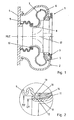
- FIG. 1 shows a turbine housing 1 of an exhaust gas turbocharger.
- the turbine housing 1 comprises an outer housing 2, which extends from a housing flange 3 to an outlet flange 4.
- the outer housing 2 is welded to both the housing flange 3 and the outlet flange 4 and defines a gas-tight interior.
- an impeller housing 5 which is formed from two sheet metal shells 6, 7, which are welded together on the outer circumference of the impeller housing 5.
- the sheet metal shell 7 shown in the left image plane has a tubular connecting piece 8 which extends in the direction of the outlet flange 4.
- a turbine wheel 17 projects into the nozzle 8, which is adapted in its contour to the outer contour of the turbine wheel 17.
- the nozzle 8 passes the emerging from the impeller housing 5 Exhaust gas via an outlet pipe 9 in the form of a bellows to the outlet flange 4, via which the exhaust gas is discharged.
- the outlet pipe 9 is welded gastight to the outlet flange 4.
- a sealing ring 10 which surrounds the pipe 8 on the outside and in FIG. 2 can be seen in an enlarged view.
- the sealing ring 10 is connected in a manner not shown with the nozzle-side end of the outlet tube 9, preferably welded or pressed with this.
- the sealing ring 10 is with its inner diameter D1 ( Figur2 ) adapted to the outer diameter of the cylindrically shaped neck 8.
- the sealing ring 10 is axially displaceable relative to the nozzle in the axial direction, ie in the direction of the central longitudinal axis MLE of the nozzle 8.
- the sealing gap 10 between the outer side 11 of the nozzle 8 and the inner side 12 is very small. This is due to the fact that the nozzle 8 has been widened in the circumferential direction by introducing an expanding mandrel, not shown, and has been pressed against the inner side 12 of the sealing ring 10.
- the defined force for widening the neck 8 has been chosen so that after removal of the expanding mandrel, the neck 8 springs back slightly, so that the desired sealing gap width results, but without leading to jamming between the sealing ring 10 and the neck 8.
- the outer diameter D2 is greater than the inner diameter D1 of the nozzle 8.
- the exhibition 13 is in this embodiment, a circumferential collar, which is 90 ° relative to the central longitudinal axis MLE of the nozzle 8 has been angled.
- a mounting ring 14 is arranged on the exhibition 13 side facing away from the sealing ring 10.
- the mounting ring 14 is adapted in its inner contour to the outer contour of the nozzle 8 and the sheet metal shell 7 and prevents the sealing ring 10 is displaced too far on the nozzle 8.
- the orientation of the position or fixation of the sealing ring 10 during assembly is important so that the expanding mandrel transfers the expansion force targeted to the sealing ring 10.
- the mounting ring 14 is made of a plastic, which melts when starting the turbocharger.
- the mounting ring 14 has the same outer diameter as the sealing ring 10th
- FIG. 3 shows an alternative embodiment in which the angle a is only 45 °. Nevertheless, it can be seen that the outer diameter D2 of the exhibition 13a is sufficiently large enough to prevent slippage of the sealing ring 10 from the nozzle 8.
- the sealing ring 10 can be placed even closer to the end of the nozzle 8, since the sealing ring 10 has an end facing chamfer 15, which is adapted in its inclination to the angle a of the exhibition 13a. In this embodiment, the angle a is about 45 °.
- the chamfer 15 is a 45 ° bevel, relative to the inner side 12 of the sealing ring 10th
- the sealing ring 10 has a measured thickness in the radial direction, which is about twice as large as the wall thickness of the nozzle 8 and the outlet tube 9.
- the sealing ring 10 is frontally slightly above the outlet pipe 9 and lies on the front side of a Collar 16 which terminates on the outside with the end 8 of the outlet pipe 9 which surrounds the connecting piece 8.
- the outer diameter of the outlet tube 9 is greater than the outer diameter of the nozzle 8. This is due to the fact that the outlet tube 9 is configured in its central region as a bellows. In the connection region to the sealing ring 10 or the outlet flange 4, there is an unshaped, in each case circular-cylindrical region, in order to enable the connection to the outlet flange 4 or the sealing ring 10.
- FIG. 4 shows a variant, with an end-side, inwardly directed eversion.
- This double-layered region of the outlet tube 9a assumes the function of the sealing ring or forms the sealing ring 10a in this exemplary embodiment.
- the nozzle 8 is expanded in a manner not shown by an expanding mandrel and pressed against the sealing ring 10a of the outlet tube 9a.
- an exhibition 13a in the form of a circumferential collar is also formed.
Landscapes
- Engineering & Computer Science (AREA)
- General Engineering & Computer Science (AREA)
- Mechanical Engineering (AREA)
- Chemical & Material Sciences (AREA)
- Chemical Kinetics & Catalysis (AREA)
- General Chemical & Material Sciences (AREA)
- Combustion & Propulsion (AREA)
- Supercharger (AREA)
Claims (16)
- Procédé de fabrication d'un boîtier de turbine d'un turbocompresseur à gaz d'échappement, comprenant un boîtier de rotor (5) agencé dans un boîtier extérieur (2) avec une tubulure (8) qui débouche dans un tube d'évacuation (9, 9a), par lequel des gaz d'échappement peuvent être transférés du boîtier de rotor (5) vers une bride d'évacuation (4) et le tube d'évacuation (9, 9a) étant couplé au boîtier de rotor (5) en déplacement relatif et une bague d'étanchéité (10, 10a) métallique agencée sur le tube d'évacuation (9, 9a) étant enfilée sur la tubulure (8), caractérisé en ce qu'un mandrin extensible est ensuite introduit dans la tubulure (8) afin de l'élargir, la tubulure (8) étant à ses extrémités au moins partiellement dirigée vers l'extérieur afin de former au moins une projection (13), dont le diamètre extérieur (D2) est supérieur au diamètre intérieur (D1) de la bague d'étanchéité (10, 10a).
- Procédé selon la revendication 1, caractérisé en ce que la tubulure (8) est pressée avec une force définie contre la bague d'étanchéité (10, 10a), la tubulure (8) se détendant après le retrait du mandrin extensible et établissant une largeur de fente définie entre la bague d'étanchéité (10, 10a) et le côté extérieur (11) de la tubulure (8).
- Procédé selon la revendication 1, caractérisé en ce que la projection (13) est réalisée en forme d'entonnoir avec un angle (a) par rapport à l'axe médian longitudinal (MLE) de la tubulure (8) dans une plage de 10 à 100°.
- Procédé selon la revendication 1 ou 3, caractérisé en ce qu'au moins deux projections (13) sont prévues.
- Procédé selon l'une quelconque des revendications 1 à 4, caractérisé en ce qu'un anneau de montage (14) est enfilé sur la tubulure (8) avant l'enfilage de la bague d'étanchéité (10) afin de déterminer la position de la bague d'étanchéité (10) dans le sens axial.
- Procédé selon l'une quelconque des revendications 1 à 5, caractérisé en ce que la bague d'étanchéité (10) est reliée par matière ou à force au tube d'évacuation (9).
- Procédé selon l'une quelconque des revendications 1 à 5, caractérisé en ce que la bague d'étanchéité (10a) est un élément d'un seul tenant du tube d'évacuation (9a) et est formée par une adaptation côté extrémité du tube d'évacuation (9a).
- Boîtier de turbine d'un turbocompresseur à gaz d'échappement, comprenant un boîtier extérieur (2), dans lequel un boîtier de rotor (5) est disposé avec une tubulure (8) et un tube d'évacuation (9, 9a), la tubulure (8) débouchant dans le tube d'évacuation (9, 9a), par lequel des gaz d'échappement peuvent être transférés de la tubulure (8) vers une bride d'évacuation (4), le tube d'évacuation (9, 9a) étant couplé en déplacement relatif au boîtier de rotor (5), et une bague d'étanchéité (10, 10a) étant disposée entre la tubulure (8) et le tube d'évacuation (9, 9a), caractérisé en ce que la tubulure (8) présente sur son extrémité au moins une projection (13) dirigée vers l'extérieur, dont le diamètre extérieur (D2) est supérieur au diamètre intérieur (D1) de la bague d'étanchéité (10, 10a).
- Boîtier de turbine selon la revendication 8, caractérisé en ce que la projection (13) présente une forme d'entonnoir avec un angle (a) par rapport à l'axe médian longitudinal (MLE) de la tubulure (8) dans une plage de 10 à 100°.
- Boîtier de turbine selon la revendication 8, caractérisé en ce qu'au moins deux projections (13) réparties sur la périphérie sont prévues.
- Boîtier de turbine selon la revendication 8, caractérisé en ce que la projection (13) est une collerette circulaire.
- Boîtier de turbine selon l'une quelconque des revendications 8 à 11, caractérisé en ce qu'un anneau de montage (14) est disposé sur la tubulure (8) sur le côté éloigné de la projection de la bague d'étanchéité (10).
- Boîtier de turbine selon la revendication 12, caractérisé en ce que l'anneau de montage (14) est en matière plastique.
- Boîtier de turbine selon l'une quelconque des revendications 8 à 13, caractérisé en ce que la bague d'étanchéité (10) est en métal et est reliée par matière ou à force au tube d'évacuation (9).
- Boîtier de turbine selon l'une quelconque des revendications 8 à 14, caractérisé en ce que la bague d'étanchéité (10a) est un élément monobloc avec le tube d'évacuation (9a) et est formée par une adaptation côté extrémité du tube d'évacuation (9a).
- Boîtier de turbine selon l'une quelconque des revendications 8 à 15, caractérisé en ce que le tube d'évacuation (9, 9a) présente une section longitudinale réalisée comme un soufflet.
Applications Claiming Priority (1)
| Application Number | Priority Date | Filing Date | Title |
|---|---|---|---|
| DE102008052552.9A DE102008052552B4 (de) | 2008-10-21 | 2008-10-21 | Turbinengehäuse und Verfahren zu seiner Herstellung |
Publications (3)
| Publication Number | Publication Date |
|---|---|
| EP2180163A2 EP2180163A2 (fr) | 2010-04-28 |
| EP2180163A3 EP2180163A3 (fr) | 2012-05-30 |
| EP2180163B1 true EP2180163B1 (fr) | 2013-06-05 |
Family
ID=41268222
Family Applications (1)
| Application Number | Title | Priority Date | Filing Date |
|---|---|---|---|
| EP09012735.8A Not-in-force EP2180163B1 (fr) | 2008-10-21 | 2009-10-08 | Boîtier de turbines et son procédé de fabrication |
Country Status (4)
| Country | Link |
|---|---|
| US (1) | US8382429B2 (fr) |
| EP (1) | EP2180163B1 (fr) |
| DE (1) | DE102008052552B4 (fr) |
| ES (1) | ES2426595T3 (fr) |
Cited By (6)
| Publication number | Priority date | Publication date | Assignee | Title |
|---|---|---|---|---|
| US10436069B2 (en) | 2017-01-30 | 2019-10-08 | Garrett Transportation I Inc. | Sheet metal turbine housing with biaxial volute configuration |
| US10472988B2 (en) | 2017-01-30 | 2019-11-12 | Garrett Transportation I Inc. | Sheet metal turbine housing and related turbocharger systems |
| US10494955B2 (en) | 2017-01-30 | 2019-12-03 | Garrett Transportation I Inc. | Sheet metal turbine housing with containment dampers |
| US10544703B2 (en) | 2017-01-30 | 2020-01-28 | Garrett Transportation I Inc. | Sheet metal turbine housing with cast core |
| US10690144B2 (en) | 2017-06-27 | 2020-06-23 | Garrett Transportation I Inc. | Compressor housings and fabrication methods |
| US11732729B2 (en) | 2021-01-26 | 2023-08-22 | Garrett Transportation I Inc | Sheet metal turbine housing |
Families Citing this family (33)
| Publication number | Priority date | Publication date | Assignee | Title |
|---|---|---|---|---|
| DE102009025054B4 (de) * | 2009-06-10 | 2015-12-03 | Benteler Automobiltechnik Gmbh | Turbinengehäuse |
| DE102009049841B4 (de) * | 2009-10-14 | 2015-01-15 | Mtu Friedrichshafen Gmbh | Gasturbomaschine und Brennkraftmaschine |
| DE102010005761A1 (de) * | 2010-01-25 | 2011-07-28 | Benteler Automobiltechnik GmbH, 33102 | Abgasbaugruppe |
| JP5769407B2 (ja) * | 2010-02-01 | 2015-08-26 | 三菱重工業株式会社 | 板金タービンハウジング |
| DE102010019404B4 (de) | 2010-05-04 | 2012-01-05 | Benteler Automobiltechnik Gmbh | Verfahren zur Herstellung eines Turboladergehäuses |
| DE102010021114A1 (de) * | 2010-05-20 | 2011-11-24 | Benteler Automobiltechnik Gmbh | Abgasturbolader |
| DE102010022218A1 (de) | 2010-05-21 | 2011-11-24 | Benteler Automobiltechnik Gmbh | Abgasturbolader |
| DE102010021973A1 (de) * | 2010-05-28 | 2011-12-01 | Bosch Mahle Turbo Systems Gmbh & Co. Kg | Ladeeinrichtung |
| ES2393720T3 (es) | 2010-09-20 | 2012-12-27 | Fiat Powertrain Technologies S.P.A. | Unidad turbosobrealimentadora con un componente auxiliar asociado para un motor de combustión interna |
| DE102010064025A1 (de) * | 2010-12-23 | 2012-06-28 | Abb Turbo Systems Ag | Berstschutz |
| DE102011050506B4 (de) * | 2011-05-19 | 2013-04-18 | Benteler Automobiltechnik Gmbh | Abgasturbolader |
| DE102012009090A1 (de) | 2012-05-09 | 2013-11-14 | Benteler Automobiltechnik Gmbh | Anbindung eines doppelwandigen Turboladergehäuses |
| DE102012109807A1 (de) * | 2012-10-15 | 2014-04-17 | Benteler Automobiltechnik Gmbh | Abgasturbolader |
| DE102013109446B4 (de) | 2013-08-30 | 2015-11-26 | Benteler Automobiltechnik Gmbh | Abgaskrümmer mit Isolationshülse |
| ITMI20131637A1 (it) * | 2013-10-03 | 2015-04-04 | Exergy Spa | Turbina di espansione |
| US9598981B2 (en) * | 2013-11-22 | 2017-03-21 | Siemens Energy, Inc. | Industrial gas turbine exhaust system diffuser inlet lip |
| DE102014102038B4 (de) | 2014-02-18 | 2016-11-24 | Benteler Automobiltechnik Gmbh | Abgasanlagen-Komponente und Verfahren zum Verbinden eines ersten Rohrbauteils und eines zweiten Rohrbauteils einer Abgasanlagen-Komponente |
| CN103925017B (zh) * | 2014-03-04 | 2015-06-17 | 大同北方天力增压技术有限公司 | 用于涡轮增压器涡轮箱的防爆裂装置 |
| DE102014103809A1 (de) | 2014-03-20 | 2015-12-03 | Benteler Automobiltechnik Gmbh | Abgaskrümmer für eine Abgasanlage eines Verbrennungsmotors |
| DE102014103820A1 (de) | 2014-03-20 | 2015-09-24 | Benteler Automobiltechnik Gmbh | Abgaskrümmer für eine Abgasanlage eines Verbrennungsmotors |
| DE102014105656B4 (de) | 2014-04-22 | 2017-02-02 | Benteler Automobiltechnik Gmbh | Abgaskrümmer |
| KR101595653B1 (ko) * | 2014-06-17 | 2016-02-19 | 한국기계연구원 | 초소형 가스터빈 |
| KR101634876B1 (ko) * | 2014-12-02 | 2016-06-30 | 한국기계연구원 | 열응력으로 인한 손상 방지구조를 갖는 초소형 가스터빈 |
| DE102015100517A1 (de) * | 2015-01-14 | 2016-07-14 | Benteler Automobiltechnik Gmbh | Turbinengehäuse für einen Abgasturbolader |
| JP6395636B2 (ja) * | 2015-02-13 | 2018-09-26 | 株式会社三五 | タービンハウジングの製造方法 |
| JP6204398B2 (ja) * | 2015-03-23 | 2017-09-27 | カルソニックカンセイ株式会社 | タービンハウジング |
| US10519806B2 (en) * | 2015-11-06 | 2019-12-31 | Calsonic Kansei Corporation | Turbine housing |
| JP6209199B2 (ja) * | 2015-12-09 | 2017-10-04 | 三菱日立パワーシステムズ株式会社 | シールフィン,シール構造,ターボ機械及びシールフィンの製造方法 |
| US10408077B2 (en) * | 2017-01-26 | 2019-09-10 | United Tehnologies Corporation | Gas turbine seal |
| WO2018179328A1 (fr) * | 2017-03-31 | 2018-10-04 | 三菱重工エンジン&ターボチャージャ株式会社 | Logement de turbine et turbocompresseur équipé de celui-ci |
| JP6735916B2 (ja) * | 2017-05-10 | 2020-08-05 | マレリ株式会社 | タービンハウジング |
| DE102018107304A1 (de) * | 2018-03-27 | 2019-10-02 | Man Energy Solutions Se | Turbolader |
| JP2019199853A (ja) * | 2018-05-18 | 2019-11-21 | カルソニックカンセイ株式会社 | タービンハウジング |
Family Cites Families (11)
| Publication number | Priority date | Publication date | Assignee | Title |
|---|---|---|---|---|
| FR2269020B3 (fr) * | 1974-04-27 | 1978-11-10 | Bosch Gmbh Robert | |
| US3965681A (en) * | 1975-06-30 | 1976-06-29 | General Motors Corporation | Internal combustion engine and turbosupercharger therefor with heat pipe for intake mixture heating |
| DE29909018U1 (de) * | 1999-05-26 | 2000-09-28 | Heinrich Gillet GmbH & Co. KG, 67480 Edenkoben | Turbinengehäuse für Abgasturbolader |
| SE0003571D0 (sv) * | 2000-10-02 | 2000-10-02 | Turbec Ab | Jointing method |
| JP2003214570A (ja) * | 2002-01-24 | 2003-07-30 | Denso Corp | 配管接続構造 |
| EP1925784B1 (fr) * | 2002-09-05 | 2011-07-20 | Honeywell International Inc. | Turbocompresseur comprenant un dispositif doté d'une buse variable |
| AU2003279321A1 (en) * | 2003-10-24 | 2005-05-19 | Honeywell International Inc. | Turbocharger with a thin-walled turbine housing having a floating flange attachment to the centre housing |
| DE10352960B4 (de) * | 2003-11-13 | 2006-06-14 | Benteler Automobiltechnik Gmbh | Gehäuseanordnung für den Turbolader einer Brennkraftmaschine |
| DE102004050302B4 (de) * | 2004-10-15 | 2010-09-30 | Norma Germany Gmbh | Verbindung zweier Rohre und Dichtring für die Verbindung |
| KR20080025367A (ko) * | 2005-07-07 | 2008-03-20 | 아사히 가라스 가부시키가이샤 | 플라즈마 디스플레이 패널용 전자파 차폐 필름 및 보호판 |
| GB2449907B (en) * | 2007-06-07 | 2010-02-10 | Gkn Aerospace Services Ltd | Composite flange and method of making such flange |
-
2008
- 2008-10-21 DE DE102008052552.9A patent/DE102008052552B4/de not_active Expired - Fee Related
-
2009
- 2009-10-08 EP EP09012735.8A patent/EP2180163B1/fr not_active Not-in-force
- 2009-10-08 ES ES09012735T patent/ES2426595T3/es active Active
- 2009-10-21 US US12/603,007 patent/US8382429B2/en not_active Expired - Fee Related
Cited By (7)
| Publication number | Priority date | Publication date | Assignee | Title |
|---|---|---|---|---|
| US10436069B2 (en) | 2017-01-30 | 2019-10-08 | Garrett Transportation I Inc. | Sheet metal turbine housing with biaxial volute configuration |
| US10472988B2 (en) | 2017-01-30 | 2019-11-12 | Garrett Transportation I Inc. | Sheet metal turbine housing and related turbocharger systems |
| US10494955B2 (en) | 2017-01-30 | 2019-12-03 | Garrett Transportation I Inc. | Sheet metal turbine housing with containment dampers |
| US10544703B2 (en) | 2017-01-30 | 2020-01-28 | Garrett Transportation I Inc. | Sheet metal turbine housing with cast core |
| US11035254B2 (en) | 2017-01-30 | 2021-06-15 | Garrett Transportation I Inc | Sheet metal turbine housing with cast core |
| US10690144B2 (en) | 2017-06-27 | 2020-06-23 | Garrett Transportation I Inc. | Compressor housings and fabrication methods |
| US11732729B2 (en) | 2021-01-26 | 2023-08-22 | Garrett Transportation I Inc | Sheet metal turbine housing |
Also Published As
| Publication number | Publication date |
|---|---|
| EP2180163A3 (fr) | 2012-05-30 |
| US8382429B2 (en) | 2013-02-26 |
| ES2426595T3 (es) | 2013-10-24 |
| DE102008052552B4 (de) | 2015-06-11 |
| DE102008052552A1 (de) | 2010-04-22 |
| US20100098533A1 (en) | 2010-04-22 |
| EP2180163A2 (fr) | 2010-04-28 |
Similar Documents
| Publication | Publication Date | Title |
|---|---|---|
| EP2180163B1 (fr) | Boîtier de turbines et son procédé de fabrication | |
| DE102009025054B4 (de) | Turbinengehäuse | |
| EP2572092B1 (fr) | Carter de turbine d'un turbocompresseur à gaz d'échappement | |
| EP2388455B1 (fr) | Turbocompresseur à gaz d'échappement | |
| EP0662564A1 (fr) | Conduit de gaz d'échappement isolé par une couche d'air et méthode de construction | |
| EP3303816B1 (fr) | Silencieux de vehicule | |
| EP2522824B1 (fr) | Composant d'installations de gaz d'échappement | |
| EP2379864A1 (fr) | Dispositif de raccordement d'une carcasse de turbine avec un corps de palier et un turbocompresseur à gaz d'échappement | |
| DE102009042260A1 (de) | Abgasturbolader | |
| DE102012009090A1 (de) | Anbindung eines doppelwandigen Turboladergehäuses | |
| WO2003091650A1 (fr) | Echangeur de chaleur de gaz d'echappement, destine en particulier a un vehicule automobile | |
| EP3114345B1 (fr) | Silencieux | |
| EP2845636A1 (fr) | Élément de filtre et procédé de fabrication d'un élément de filtre | |
| DE102011118862B4 (de) | Modularer Flansch | |
| EP3245396B1 (fr) | Silenciux pour vehicule | |
| DE102020130205A1 (de) | Schallminderer und Verfahren zu dessen Herstellung | |
| EP1704001B1 (fr) | Composant cintre a deux parois, par exemple tuyau pour gaz d'echappement isole par lame d'air, et son procede de production | |
| DE102013210982A1 (de) | Dehnkörper zur Verbindung von zwei Rohrstücken insbesondere eines Abgaskanals eines Kraftfahrzeugs sowie Abgasturboladereinheit mit einem derartigen Dehnkörper | |
| DE202010017187U1 (de) | Mehrteiliges Turboladergehäuse | |
| DE10357953B4 (de) | Halterung für eine Abgasreinigungskomponente eines Abgassystems | |
| WO2012035163A1 (fr) | Unité de traitement de gaz d'échappement pour une conduite de recyclage de gaz d'échappement | |
| EP3209876B1 (fr) | Silencieux de vehicule pour la conduite d'air comprimé d'un moteur à combustion | |
| EP3196579A1 (fr) | Échangeur de chaleur | |
| EP2894312B1 (fr) | Élément de conduite flexible avec isolation | |
| DE19812611C2 (de) | Entkopplungselement in Rohrleitungen |
Legal Events
| Date | Code | Title | Description |
|---|---|---|---|
| PUAI | Public reference made under article 153(3) epc to a published international application that has entered the european phase |
Free format text: ORIGINAL CODE: 0009012 |
|
| AK | Designated contracting states |
Kind code of ref document: A2 Designated state(s): AT BE BG CH CY CZ DE DK EE ES FI FR GB GR HR HU IE IS IT LI LT LU LV MC MK MT NL NO PL PT RO SE SI SK SM TR |
|
| AX | Request for extension of the european patent |
Extension state: AL BA RS |
|
| PUAL | Search report despatched |
Free format text: ORIGINAL CODE: 0009013 |
|
| AK | Designated contracting states |
Kind code of ref document: A3 Designated state(s): AT BE BG CH CY CZ DE DK EE ES FI FR GB GR HR HU IE IS IT LI LT LU LV MC MK MT NL NO PL PT RO SE SI SK SM TR |
|
| AX | Request for extension of the european patent |
Extension state: AL BA RS |
|
| RIC1 | Information provided on ipc code assigned before grant |
Ipc: F02C 6/12 20060101AFI20120426BHEP Ipc: F01D 9/02 20060101ALI20120426BHEP Ipc: F16J 15/34 20060101ALI20120426BHEP Ipc: F01D 25/24 20060101ALI20120426BHEP Ipc: F01D 11/02 20060101ALI20120426BHEP |
|
| 17P | Request for examination filed |
Effective date: 20121109 |
|
| GRAP | Despatch of communication of intention to grant a patent |
Free format text: ORIGINAL CODE: EPIDOSNIGR1 |
|
| RIN1 | Information on inventor provided before grant (corrected) |
Inventor name: SMATLOCH, CHRISTIAN Inventor name: GRUSSMANN, ELMAR |
|
| GRAS | Grant fee paid |
Free format text: ORIGINAL CODE: EPIDOSNIGR3 |
|
| GRAA | (expected) grant |
Free format text: ORIGINAL CODE: 0009210 |
|
| AK | Designated contracting states |
Kind code of ref document: B1 Designated state(s): AT BE BG CH CY CZ DE DK EE ES FI FR GB GR HR HU IE IS IT LI LT LU LV MC MK MT NL NO PL PT RO SE SI SK SM TR |
|
| REG | Reference to a national code |
Ref country code: GB Ref legal event code: FG4D Free format text: NOT ENGLISH |
|
| REG | Reference to a national code |
Ref country code: CH Ref legal event code: EP |
|
| REG | Reference to a national code |
Ref country code: AT Ref legal event code: REF Ref document number: 615800 Country of ref document: AT Kind code of ref document: T Effective date: 20130615 |
|
| REG | Reference to a national code |
Ref country code: IE Ref legal event code: FG4D Free format text: LANGUAGE OF EP DOCUMENT: GERMAN |
|
| REG | Reference to a national code |
Ref country code: DE Ref legal event code: R096 Ref document number: 502009007274 Country of ref document: DE Effective date: 20130801 |
|
| REG | Reference to a national code |
Ref country code: SE Ref legal event code: TRGR |
|
| REG | Reference to a national code |
Ref country code: ES Ref legal event code: FG2A Ref document number: 2426595 Country of ref document: ES Kind code of ref document: T3 Effective date: 20131024 |
|
| PG25 | Lapsed in a contracting state [announced via postgrant information from national office to epo] |
Ref country code: LT Free format text: LAPSE BECAUSE OF FAILURE TO SUBMIT A TRANSLATION OF THE DESCRIPTION OR TO PAY THE FEE WITHIN THE PRESCRIBED TIME-LIMIT Effective date: 20130605 Ref country code: NO Free format text: LAPSE BECAUSE OF FAILURE TO SUBMIT A TRANSLATION OF THE DESCRIPTION OR TO PAY THE FEE WITHIN THE PRESCRIBED TIME-LIMIT Effective date: 20130905 Ref country code: SI Free format text: LAPSE BECAUSE OF FAILURE TO SUBMIT A TRANSLATION OF THE DESCRIPTION OR TO PAY THE FEE WITHIN THE PRESCRIBED TIME-LIMIT Effective date: 20130605 Ref country code: FI Free format text: LAPSE BECAUSE OF FAILURE TO SUBMIT A TRANSLATION OF THE DESCRIPTION OR TO PAY THE FEE WITHIN THE PRESCRIBED TIME-LIMIT Effective date: 20130605 Ref country code: GR Free format text: LAPSE BECAUSE OF FAILURE TO SUBMIT A TRANSLATION OF THE DESCRIPTION OR TO PAY THE FEE WITHIN THE PRESCRIBED TIME-LIMIT Effective date: 20130906 |
|
| REG | Reference to a national code |
Ref country code: NL Ref legal event code: VDEP Effective date: 20130605 |
|
| REG | Reference to a national code |
Ref country code: LT Ref legal event code: MG4D |
|
| PG25 | Lapsed in a contracting state [announced via postgrant information from national office to epo] |
Ref country code: BG Free format text: LAPSE BECAUSE OF FAILURE TO SUBMIT A TRANSLATION OF THE DESCRIPTION OR TO PAY THE FEE WITHIN THE PRESCRIBED TIME-LIMIT Effective date: 20130905 Ref country code: HR Free format text: LAPSE BECAUSE OF FAILURE TO SUBMIT A TRANSLATION OF THE DESCRIPTION OR TO PAY THE FEE WITHIN THE PRESCRIBED TIME-LIMIT Effective date: 20130605 Ref country code: PL Free format text: LAPSE BECAUSE OF FAILURE TO SUBMIT A TRANSLATION OF THE DESCRIPTION OR TO PAY THE FEE WITHIN THE PRESCRIBED TIME-LIMIT Effective date: 20130605 |
|
| PG25 | Lapsed in a contracting state [announced via postgrant information from national office to epo] |
Ref country code: LV Free format text: LAPSE BECAUSE OF FAILURE TO SUBMIT A TRANSLATION OF THE DESCRIPTION OR TO PAY THE FEE WITHIN THE PRESCRIBED TIME-LIMIT Effective date: 20130605 |
|
| PG25 | Lapsed in a contracting state [announced via postgrant information from national office to epo] |
Ref country code: IS Free format text: LAPSE BECAUSE OF FAILURE TO SUBMIT A TRANSLATION OF THE DESCRIPTION OR TO PAY THE FEE WITHIN THE PRESCRIBED TIME-LIMIT Effective date: 20131005 Ref country code: SK Free format text: LAPSE BECAUSE OF FAILURE TO SUBMIT A TRANSLATION OF THE DESCRIPTION OR TO PAY THE FEE WITHIN THE PRESCRIBED TIME-LIMIT Effective date: 20130605 Ref country code: CZ Free format text: LAPSE BECAUSE OF FAILURE TO SUBMIT A TRANSLATION OF THE DESCRIPTION OR TO PAY THE FEE WITHIN THE PRESCRIBED TIME-LIMIT Effective date: 20130605 Ref country code: PT Free format text: LAPSE BECAUSE OF FAILURE TO SUBMIT A TRANSLATION OF THE DESCRIPTION OR TO PAY THE FEE WITHIN THE PRESCRIBED TIME-LIMIT Effective date: 20131007 Ref country code: EE Free format text: LAPSE BECAUSE OF FAILURE TO SUBMIT A TRANSLATION OF THE DESCRIPTION OR TO PAY THE FEE WITHIN THE PRESCRIBED TIME-LIMIT Effective date: 20130605 |
|
| PG25 | Lapsed in a contracting state [announced via postgrant information from national office to epo] |
Ref country code: RO Free format text: LAPSE BECAUSE OF FAILURE TO SUBMIT A TRANSLATION OF THE DESCRIPTION OR TO PAY THE FEE WITHIN THE PRESCRIBED TIME-LIMIT Effective date: 20130605 Ref country code: NL Free format text: LAPSE BECAUSE OF FAILURE TO SUBMIT A TRANSLATION OF THE DESCRIPTION OR TO PAY THE FEE WITHIN THE PRESCRIBED TIME-LIMIT Effective date: 20130605 |
|
| PLBE | No opposition filed within time limit |
Free format text: ORIGINAL CODE: 0009261 |
|
| STAA | Information on the status of an ep patent application or granted ep patent |
Free format text: STATUS: NO OPPOSITION FILED WITHIN TIME LIMIT |
|
| BERE | Be: lapsed |
Owner name: BENTELER AUTOMOBILTECHNIK G.M.B.H. Effective date: 20131031 |
|
| PG25 | Lapsed in a contracting state [announced via postgrant information from national office to epo] |
Ref country code: DK Free format text: LAPSE BECAUSE OF FAILURE TO SUBMIT A TRANSLATION OF THE DESCRIPTION OR TO PAY THE FEE WITHIN THE PRESCRIBED TIME-LIMIT Effective date: 20130605 |
|
| 26N | No opposition filed |
Effective date: 20140306 |
|
| PG25 | Lapsed in a contracting state [announced via postgrant information from national office to epo] |
Ref country code: MC Free format text: LAPSE BECAUSE OF FAILURE TO SUBMIT A TRANSLATION OF THE DESCRIPTION OR TO PAY THE FEE WITHIN THE PRESCRIBED TIME-LIMIT Effective date: 20130605 |
|
| REG | Reference to a national code |
Ref country code: CH Ref legal event code: PL |
|
| REG | Reference to a national code |
Ref country code: DE Ref legal event code: R097 Ref document number: 502009007274 Country of ref document: DE Effective date: 20140306 |
|
| GBPC | Gb: european patent ceased through non-payment of renewal fee |
Effective date: 20131008 |
|
| REG | Reference to a national code |
Ref country code: IE Ref legal event code: MM4A |
|
| PG25 | Lapsed in a contracting state [announced via postgrant information from national office to epo] |
Ref country code: LI Free format text: LAPSE BECAUSE OF NON-PAYMENT OF DUE FEES Effective date: 20131031 Ref country code: CH Free format text: LAPSE BECAUSE OF NON-PAYMENT OF DUE FEES Effective date: 20131031 Ref country code: GB Free format text: LAPSE BECAUSE OF NON-PAYMENT OF DUE FEES Effective date: 20131008 |
|
| PG25 | Lapsed in a contracting state [announced via postgrant information from national office to epo] |
Ref country code: BE Free format text: LAPSE BECAUSE OF NON-PAYMENT OF DUE FEES Effective date: 20131031 |
|
| PG25 | Lapsed in a contracting state [announced via postgrant information from national office to epo] |
Ref country code: IE Free format text: LAPSE BECAUSE OF NON-PAYMENT OF DUE FEES Effective date: 20131008 |
|
| PG25 | Lapsed in a contracting state [announced via postgrant information from national office to epo] |
Ref country code: SM Free format text: LAPSE BECAUSE OF FAILURE TO SUBMIT A TRANSLATION OF THE DESCRIPTION OR TO PAY THE FEE WITHIN THE PRESCRIBED TIME-LIMIT Effective date: 20130605 |
|
| PG25 | Lapsed in a contracting state [announced via postgrant information from national office to epo] |
Ref country code: CY Free format text: LAPSE BECAUSE OF FAILURE TO SUBMIT A TRANSLATION OF THE DESCRIPTION OR TO PAY THE FEE WITHIN THE PRESCRIBED TIME-LIMIT Effective date: 20130605 Ref country code: TR Free format text: LAPSE BECAUSE OF FAILURE TO SUBMIT A TRANSLATION OF THE DESCRIPTION OR TO PAY THE FEE WITHIN THE PRESCRIBED TIME-LIMIT Effective date: 20130605 |
|
| PG25 | Lapsed in a contracting state [announced via postgrant information from national office to epo] |
Ref country code: LU Free format text: LAPSE BECAUSE OF NON-PAYMENT OF DUE FEES Effective date: 20131008 Ref country code: HU Free format text: LAPSE BECAUSE OF FAILURE TO SUBMIT A TRANSLATION OF THE DESCRIPTION OR TO PAY THE FEE WITHIN THE PRESCRIBED TIME-LIMIT; INVALID AB INITIO Effective date: 20091008 Ref country code: MK Free format text: LAPSE BECAUSE OF FAILURE TO SUBMIT A TRANSLATION OF THE DESCRIPTION OR TO PAY THE FEE WITHIN THE PRESCRIBED TIME-LIMIT Effective date: 20130605 |
|
| PG25 | Lapsed in a contracting state [announced via postgrant information from national office to epo] |
Ref country code: MT Free format text: LAPSE BECAUSE OF FAILURE TO SUBMIT A TRANSLATION OF THE DESCRIPTION OR TO PAY THE FEE WITHIN THE PRESCRIBED TIME-LIMIT Effective date: 20130605 |
|
| REG | Reference to a national code |
Ref country code: FR Ref legal event code: PLFP Year of fee payment: 7 |
|
| REG | Reference to a national code |
Ref country code: AT Ref legal event code: MM01 Ref document number: 615800 Country of ref document: AT Kind code of ref document: T Effective date: 20141008 |
|
| PG25 | Lapsed in a contracting state [announced via postgrant information from national office to epo] |
Ref country code: AT Free format text: LAPSE BECAUSE OF NON-PAYMENT OF DUE FEES Effective date: 20141008 |
|
| REG | Reference to a national code |
Ref country code: FR Ref legal event code: PLFP Year of fee payment: 8 |
|
| PGFP | Annual fee paid to national office [announced via postgrant information from national office to epo] |
Ref country code: FR Payment date: 20161020 Year of fee payment: 8 |
|
| PGFP | Annual fee paid to national office [announced via postgrant information from national office to epo] |
Ref country code: SE Payment date: 20161019 Year of fee payment: 8 Ref country code: ES Payment date: 20161011 Year of fee payment: 8 Ref country code: IT Payment date: 20161024 Year of fee payment: 8 |
|
| REG | Reference to a national code |
Ref country code: SE Ref legal event code: EUG |
|
| REG | Reference to a national code |
Ref country code: FR Ref legal event code: ST Effective date: 20180629 |
|
| PG25 | Lapsed in a contracting state [announced via postgrant information from national office to epo] |
Ref country code: SE Free format text: LAPSE BECAUSE OF NON-PAYMENT OF DUE FEES Effective date: 20171009 Ref country code: FR Free format text: LAPSE BECAUSE OF NON-PAYMENT OF DUE FEES Effective date: 20171031 |
|
| PG25 | Lapsed in a contracting state [announced via postgrant information from national office to epo] |
Ref country code: IT Free format text: LAPSE BECAUSE OF NON-PAYMENT OF DUE FEES Effective date: 20171008 |
|
| REG | Reference to a national code |
Ref country code: ES Ref legal event code: FD2A Effective date: 20181220 |
|
| PG25 | Lapsed in a contracting state [announced via postgrant information from national office to epo] |
Ref country code: ES Free format text: LAPSE BECAUSE OF NON-PAYMENT OF DUE FEES Effective date: 20171009 |
|
| PGFP | Annual fee paid to national office [announced via postgrant information from national office to epo] |
Ref country code: DE Payment date: 20201217 Year of fee payment: 12 |
|
| REG | Reference to a national code |
Ref country code: DE Ref legal event code: R119 Ref document number: 502009007274 Country of ref document: DE |
|
| PG25 | Lapsed in a contracting state [announced via postgrant information from national office to epo] |
Ref country code: DE Free format text: LAPSE BECAUSE OF NON-PAYMENT OF DUE FEES Effective date: 20220503 |