EP2180257A2 - Appareil pour simuler une flamme ou un feu avec un laser et un générateur de brouillard - Google Patents
Appareil pour simuler une flamme ou un feu avec un laser et un générateur de brouillard Download PDFInfo
- Publication number
- EP2180257A2 EP2180257A2 EP08009901A EP08009901A EP2180257A2 EP 2180257 A2 EP2180257 A2 EP 2180257A2 EP 08009901 A EP08009901 A EP 08009901A EP 08009901 A EP08009901 A EP 08009901A EP 2180257 A2 EP2180257 A2 EP 2180257A2
- Authority
- EP
- European Patent Office
- Prior art keywords
- mist
- laser
- light effect
- effect device
- fan
- Prior art date
- Legal status (The legal status is an assumption and is not a legal conclusion. Google has not performed a legal analysis and makes no representation as to the accuracy of the status listed.)
- Withdrawn
Links
- 239000003595 mist Substances 0.000 title claims abstract description 64
- XLYOFNOQVPJJNP-UHFFFAOYSA-N water Substances O XLYOFNOQVPJJNP-UHFFFAOYSA-N 0.000 claims description 26
- 230000001795 light effect Effects 0.000 claims description 25
- 239000012528 membrane Substances 0.000 claims description 9
- 239000003086 colorant Substances 0.000 claims description 2
- 239000007788 liquid Substances 0.000 claims 1
- 230000032258 transport Effects 0.000 abstract description 2
- 239000003570 air Substances 0.000 description 23
- 230000000694 effects Effects 0.000 description 4
- 239000000203 mixture Substances 0.000 description 3
- 239000000126 substance Substances 0.000 description 3
- 230000001914 calming effect Effects 0.000 description 2
- 239000004744 fabric Substances 0.000 description 2
- 238000012423 maintenance Methods 0.000 description 2
- 241000894006 Bacteria Species 0.000 description 1
- 241000475481 Nebula Species 0.000 description 1
- 239000011358 absorbing material Substances 0.000 description 1
- 239000012080 ambient air Substances 0.000 description 1
- 244000052616 bacterial pathogen Species 0.000 description 1
- 230000009286 beneficial effect Effects 0.000 description 1
- 239000006227 byproduct Substances 0.000 description 1
- 238000004140 cleaning Methods 0.000 description 1
- 238000010276 construction Methods 0.000 description 1
- 238000011109 contamination Methods 0.000 description 1
- 239000000428 dust Substances 0.000 description 1
- 230000008020 evaporation Effects 0.000 description 1
- 238000001704 evaporation Methods 0.000 description 1
- 239000000446 fuel Substances 0.000 description 1
- 239000011521 glass Substances 0.000 description 1
- 230000036541 health Effects 0.000 description 1
- 231100000206 health hazard Toxicity 0.000 description 1
- 230000010355 oscillation Effects 0.000 description 1
- 238000013021 overheating Methods 0.000 description 1
- 230000000149 penetrating effect Effects 0.000 description 1
- 230000008092 positive effect Effects 0.000 description 1
- 230000036642 wellbeing Effects 0.000 description 1
Images


Classifications
-
- F—MECHANICAL ENGINEERING; LIGHTING; HEATING; WEAPONS; BLASTING
- F21—LIGHTING
- F21S—NON-PORTABLE LIGHTING DEVICES; SYSTEMS THEREOF; VEHICLE LIGHTING DEVICES SPECIALLY ADAPTED FOR VEHICLE EXTERIORS
- F21S10/00—Lighting devices or systems producing a varying lighting effect
- F21S10/04—Lighting devices or systems producing a varying lighting effect simulating flames
-
- F—MECHANICAL ENGINEERING; LIGHTING; HEATING; WEAPONS; BLASTING
- F24—HEATING; RANGES; VENTILATING
- F24C—DOMESTIC STOVES OR RANGES ; DETAILS OF DOMESTIC STOVES OR RANGES, OF GENERAL APPLICATION
- F24C7/00—Stoves or ranges heated by electric energy
- F24C7/002—Stoves
- F24C7/004—Stoves simulating flames
Definitions
- the present invention relates to a light effect device for generating a light effect similar to the flame of a fire with a mist generator, at least one line laser, a fan and at least one profile strip.
- line lasers In contrast to point lasers, line lasers not only create a light spot on a projection surface, but also a straight line of light. In this case, the laser light spreads flat and fan-shaped and generates, for example, when it strikes a wall, a clearly visible straight line of light. These line lasers are often used on construction sites to build straight walls using the light line or to mount windows or beams at exactly the same height.
- Fog generators are devices that produce mists of water, chemicals or a mixture of both. They are used to humidify air in dry living rooms or to beautify the room when this fog is illuminated with LEDs. Artificially generated fog is also used in large quantities on music stages as a show effect.
- an ultrasonic mist generator is preferably used.
- a membrane is electrically offset into high-frequency oscillations. This membrane in turn causes the surrounding water to vibrate, causing the water to become cloudy.
- mist generators may be used, for example, devices that use water to vaporize water, chemicals or a mixture of both. Such mist generators are often used in discotheques and on music stages to produce large amounts of fog.
- Fans, blowers or even motor-driven propellers are used to transport used air out of rooms, to provide a refreshing air movement at high temperatures or to protect technical equipment against overheating.
- a real fire, with a visible flame, to operate in an apartment is possible only with great effort. It requires an open fireplace or a glass door oven. It still needs to be procured fuel. Operation and cleaning mean a considerable effort. Additional disadvantages are resulting dirt, odor and fire hazard.
- the light effect device presented here mimics the appearance of a flame, but has the following advantages over a fire:
- the light effect device presented here has a low power consumption and the advantage that in addition to the light effect, an effective humidification is achieved.
- Purpose of the invention is to combine the calming effect of a fire light with simultaneous humidification. This should be done in continuous, low-maintenance as possible continuous operation. Fire hazard, dirt and odor nuisance should be excluded.
- the light of the line laser is reflected by the fine mist droplets. Starting from the fog-free rooms no fog is reflected. Overall, the constant change of position of rooms with fog and rooms without fog, constantly changing light reflections, emitted by the line laser light. These ever-changing light reflections are very similar to the flame of a fire. This lighting effect has a very calming effect on the viewer. At the same time, the generated mist is intensively mixed with the ambient air by the air flow. This achieves effective room humidification. Since the room air is often dried up by radiators, especially in winter, this has an additional positive effect on the well-being of the residents.
- the fog penetrating laser beams hit on one or more profile strips open to one side.
- This profile strip extends over the entire length of the light line, which is generated by the line laser and serves as a so-called beam trap.
- the laser light initially penetrates into the profile strip which is open to one side.
- the laser light is stopped and thus can not further, beyond the outlines of the light effect device, penetrate. This protects the viewer or passer-by from looking directly into the laser beam and thus from intense laser light. Lateral reflections of the laser light, starting from the bottom of the profile strip, are largely stopped by the side walls of the profile strip. This serves to protect the viewer from looking directly into the reflected laser light from the bottom of the light bar.
- the profiled strip described above can also be replaced by a highly light absorbing material, such as black fabric or velvet.
- the base of the light effect device When used in a dwelling, the base of the light effect device preferably consists of a downwardly and laterally completely enclosed tub that collects falling mist to prevent excessive humidification of the surrounding environment, for example moisture-sensitive floors and furniture.
- the ultrasonic mist generator along with the supply of water that is being atomized, may be in a simple watertight pan over which the mist then floats and is carried along by the fan's airflow.
- the ultrasonic mist generator can also be located in a largely closed container with a water supply, which must have openings for air supply and air removal for the mist.
- the mist can also be produced by any other type of mist generator and directed by means of a fan into the laser beam (s) of one or more line lasers.
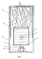
- the first embodiment explained refers to the drawings in Fig. 1 to Fig. 5 ,
- the basic framework and mounting base of all components of the embodiment explained above is a water-tight trough 9 which is closed downwards and closed on all sides but open at the top, inside, preferably dark and / or matt black.
- the power supply 20 all the electrically operated components, which are here the ultrasonic mist generator 3, the line laser 1 and the fan 15, supplied with electrical voltage.
- the laid in the light effect device power cables are not shown for clarity.
- On the bottom of the tub 9 is another only open at the top, preferably completely dark and / or matte black colored, waterproof tub. 5
- this tub 5 there is an ultrasonic mist generator 3 with a membrane 4, which is installed somewhat recessed in a shaft.
- the mist generator 3 and thus also the membrane 4 are immersed in water 6.
- the membrane 4 of the mist generator 3 is electrically vibrated and thus also the surrounding water 6. As a result, the surrounding water 6 is converted into the finest fog-like droplets 17.
- the mist generator is a cup-shaped splash guard 10 which is mounted on four rods 11.
- This splash guard 10 stops from the membrane 4 thrown upwards larger drops of water that arise as a byproduct in the mist generation, which then back into the Drain pan 5 back. This prevents these large drops of water from disturbing the desired effect.
- a more economical water consumption is achieved because these drops do not leave the tub 5 unused, but also can be turned into fog.
- this splash guard 10 is so far above the water surface that enough fog can escape laterally between the rods 11.
- the ultrasonic mist generator 3 is set up so that it constantly generates mist 17, which initially floats above the surface of the water 6.
- the fog 17 is shown for the sake of clarity only in the form of a few individual points.
- the side of the tub 9 is a fan 15 with motor 13, motor mounts 14 and propeller 12.
- This fan 15 sucks air through the opening 16 and blows this air in the direction of the over the tub 5 floating fog 17.
- the initially dense fog 17 is entrained by the air flow of the fan 15.
- the air supplied by the fan 15 mixes with the mist 17, and there are constantly changing rooms with fog 17, and rooms without fog.
- a line laser module 1 located laterally on the trough 9 is a line laser module 1 in the housing 2.
- This line laser module 1 generates a flat, starting from the line laser 1 wedge-shaped diverging laser beam 7 which is directed into the generated by the fan 15 and 17 mixed with mist air flow.
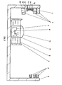
- Fig. 5 shows that the area which outshines the laser light 7 is wedge-shaped starting from the line laser 1 and is delimited by three profile strips 8.
- Fig. 2 shows parts of the laser light 7, which are visible in the nebulous swaths 27, viewed from the side as thin glowing stripes, since the fine nebulas 27 reflect the laser light 7. From the spaces between the nebulosity 27 no light is reflected. Therefore, the laser light 7 is not visible there.
- one side open, preferably dark and / or matte black colored profile strips. 8
- profile strips 8 can also be mounted above the walls of the trough 9 on this trough 9. These profile strips 8 serve the purpose that viewers or passers-by can not see directly into the laser beam 7 generated by the laser module 1. This is one, depending on the intensity of the laser beam 7, required action to avoid a health hazard to the eyes of an observer. These profile strips 8 are positioned so that the light beam 7 of the line laser 1 enters exactly in the open side. There the laser beam is partly absorbed and partly reflected.
- Fig. 4 shows the course of the laser beams 7, starting from the laser module 1 to a profile strip 8 with the course of the reflections 18 of the laser light 7 within the profile strip 8.
- the laser beams reflected from the bottom of the profile strip 8 can not leave the light effect device upwards, as they from the top and lower side of the profile strip 8 are prevented from exiting.
- the profile strips 8 are also positioned within the trough 9 on three walls of this trough 9 so that the entire light line generated by the line laser 1 impinges on the bottom of the profile strips 8.
- Fig. 6 shows a variant of the light effect device with multiple line lasers 1 and a plurality of profile strips 8 and shows their possible arrangement in different heights and angles. For clarity, the view has been shown here in the off state, so no fog 17 and no laser light 7 is visible.
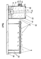
- Fig. 7 and Fig. 8 show a further variant of the light effect device.
- a drip tray 9 as in Fig. 2 here is a stainless, preferably dark colored plate 24, the mounting base of all other components.
- This version can be used when the light effect device is operated in a wet insensitive location and therefore no sinking mist 17 has to be collected. This saves the Weggemie involved collected water 6, which is when using the drip tray 9 in Fig. 2 from time to time is required.
- this container 21 are also an ultrasonic mist generator 3 with the membrane 4 and a splash guard 10 with support posts 11th
- the ultrasonic mist generator 3 also produces continuous mist 17 here and the splash guard 10 prevents larger drops from the water 6 fall into the air flow of the fan 15.
- the fan 15 is located directly on the outside of the container 21 and carries air through the opening 23 in the container 21st This air occurs mixed with mist 17 under pressure at the opening 24 again and conveys the mist 28 between the profile strip 8 and line laser 1 along the laser beams 7.
- the container 21 has the advantage over the tub 5 the water 6 better against contamination with dust and Protecting germs with bacteria.
- other types of mist generators for example those which generate mist by evaporation of water, may be accommodated instead of an ultrasonic mist generator 3, the mist 17 always being fed from the fan 15 through one or more openings 24 out of the container along the Laser beams 7 is transported.
Landscapes
- Engineering & Computer Science (AREA)
- General Engineering & Computer Science (AREA)
- Chemical & Material Sciences (AREA)
- Combustion & Propulsion (AREA)
- Mechanical Engineering (AREA)
- Laser Beam Processing (AREA)
- Nozzles (AREA)
Priority Applications (1)
| Application Number | Priority Date | Filing Date | Title |
|---|---|---|---|
| EP08009901A EP2180257A3 (fr) | 2008-05-30 | 2008-05-30 | Appareil pour simuler une flamme ou un feu avec un laser et un générateur de brouillard |
Applications Claiming Priority (1)
| Application Number | Priority Date | Filing Date | Title |
|---|---|---|---|
| EP08009901A EP2180257A3 (fr) | 2008-05-30 | 2008-05-30 | Appareil pour simuler une flamme ou un feu avec un laser et un générateur de brouillard |
Publications (2)
| Publication Number | Publication Date |
|---|---|
| EP2180257A2 true EP2180257A2 (fr) | 2010-04-28 |
| EP2180257A3 EP2180257A3 (fr) | 2010-05-12 |
Family
ID=42026139
Family Applications (1)
| Application Number | Title | Priority Date | Filing Date |
|---|---|---|---|
| EP08009901A Withdrawn EP2180257A3 (fr) | 2008-05-30 | 2008-05-30 | Appareil pour simuler une flamme ou un feu avec un laser et un générateur de brouillard |
Country Status (1)
| Country | Link |
|---|---|
| EP (1) | EP2180257A3 (fr) |
Cited By (1)
| Publication number | Priority date | Publication date | Assignee | Title |
|---|---|---|---|---|
| CN109307310A (zh) * | 2018-12-12 | 2019-02-05 | 江门市科业电器制造有限公司 | 一种仿真电壁炉 |
Citations (2)
| Publication number | Priority date | Publication date | Assignee | Title |
|---|---|---|---|---|
| DE3517852A1 (de) | 1985-05-17 | 1986-11-20 | Werner Zürich Vögeli | Lichteffektanlage fuer diskotheken |
| DE4115499A1 (de) | 1991-05-11 | 1992-11-12 | Martin Dr Bechem | Herstellung, vertrieb und anwendung einer nebelmaschine zum gezielten, gerichteten und gesteuerten gasausstoss |
Family Cites Families (8)
| Publication number | Priority date | Publication date | Assignee | Title |
|---|---|---|---|---|
| US5989128A (en) * | 1998-01-08 | 1999-11-23 | Universal Studios, Inc. | Flame simulation |
| GB0202152D0 (en) * | 2002-01-30 | 2002-03-20 | Valor Ltd | Smoke effect apparatus |
| US7762897B2 (en) * | 2002-04-04 | 2010-07-27 | Technifex, Inc. | Apparatus for producing a fire special effect |
| DE102004019198A1 (de) * | 2004-04-16 | 2005-11-10 | Gernot Ehrlich | Vernebelungsgerät |
| GB2418014B (en) * | 2004-09-10 | 2009-05-06 | Basic Holdings | Apparatus for producing an optical effect |
| GB0605001D0 (en) * | 2006-03-13 | 2006-04-19 | Basic Holdings | Fuel and flame effect fires |
| DE102006014734A1 (de) * | 2006-03-30 | 2007-10-11 | Mölders, Stephan, Dr. | Die Tornadomaschine - Ein Nebel-Wirbler, der als Effektgerät, Luftbefeuchter und Aerosolgenerator einsetzbar ist |
| DE102006057504B3 (de) * | 2006-12-06 | 2008-05-21 | Schüngel, Friedrich | Lichteffekt-Vorrichtung |
-
2008
- 2008-05-30 EP EP08009901A patent/EP2180257A3/fr not_active Withdrawn
Patent Citations (2)
| Publication number | Priority date | Publication date | Assignee | Title |
|---|---|---|---|---|
| DE3517852A1 (de) | 1985-05-17 | 1986-11-20 | Werner Zürich Vögeli | Lichteffektanlage fuer diskotheken |
| DE4115499A1 (de) | 1991-05-11 | 1992-11-12 | Martin Dr Bechem | Herstellung, vertrieb und anwendung einer nebelmaschine zum gezielten, gerichteten und gesteuerten gasausstoss |
Cited By (1)
| Publication number | Priority date | Publication date | Assignee | Title |
|---|---|---|---|---|
| CN109307310A (zh) * | 2018-12-12 | 2019-02-05 | 江门市科业电器制造有限公司 | 一种仿真电壁炉 |
Also Published As
| Publication number | Publication date |
|---|---|
| EP2180257A3 (fr) | 2010-05-12 |
Similar Documents
| Publication | Publication Date | Title |
|---|---|---|
| DE602004006717T2 (de) | Verdunstungsvorrichtung für flüchtige Wirkstoffe | |
| DE60011489T2 (de) | Vorrichtung zum Vortäuschen einer Flamme | |
| DE1904280A1 (de) | Vorrichtung zur Erzeugung von Lichteffekten | |
| DE202018001632U1 (de) | Kompakte Zerstäubungsvorrichtung, und Zerstäubungsanordnung, die eine solche Vorrichtung umfasst | |
| DE202008000690U1 (de) | Fluginsektenfalle | |
| DE102006014734A1 (de) | Die Tornadomaschine - Ein Nebel-Wirbler, der als Effektgerät, Luftbefeuchter und Aerosolgenerator einsetzbar ist | |
| EP0666453A2 (fr) | Procédé et dispositif pour la purification et l'humidification de l'air | |
| DE102007022312B3 (de) | Lichteffektvorrichtung | |
| EP1073934A1 (fr) | Lampe de projection pour la projection d'effets lumineux colores | |
| DE102020126096B4 (de) | Vorrichtung zur reinigung von raumluft | |
| EP0516085B1 (fr) | Dispositif de climatisation d'un local | |
| DE202006014352U1 (de) | Leuchte mit wenigstens einer lichtdurchlässigen Abdeckung | |
| EP2180257A2 (fr) | Appareil pour simuler une flamme ou un feu avec un laser et un générateur de brouillard | |
| DE1837277U (de) | Vorrichtung zur befeuchtung und reinigung von raumluft. | |
| DE9207238U1 (de) | Tragbares Gerät zum Verteilen befeuchteter und abgekühlter Luft | |
| DE102010050858A1 (de) | Lichteffektvorrichtung | |
| DE60312926T2 (de) | Gewächshaus kleinerer Baugrösse mit einer kontrollierten internen Umgebung | |
| DE3313399A1 (de) | Kuehltheke | |
| DE19959149A1 (de) | Projektionsleuchte zur Projektion farbiger Lichteffekte | |
| EP0070870A1 (fr) | Dispositif pour aspirer du brouillard de peinture. | |
| DE19516661A1 (de) | Vorrichtung zum Befeuchten und Reinigen von Luft | |
| DE102006057504B3 (de) | Lichteffekt-Vorrichtung | |
| DE2634011A1 (de) | Verfahren zum emittieren eines fluechtigen stoffes und vorrichtung zum durchfuehren des verfahrens | |
| AT224313B (de) | Einrichtung zur Befeuchtung und Reinigung von Raumluft | |
| DE20210830U1 (de) | Werbeträger mit Duftspender |
Legal Events
| Date | Code | Title | Description |
|---|---|---|---|
| PUAI | Public reference made under article 153(3) epc to a published international application that has entered the european phase |
Free format text: ORIGINAL CODE: 0009012 |
|
| PUAL | Search report despatched |
Free format text: ORIGINAL CODE: 0009013 |
|
| AK | Designated contracting states |
Kind code of ref document: A2 Designated state(s): AT BE BG CH CY CZ DE DK EE ES FI FR GB GR HR HU IE IS IT LI LT LU LV MC MT NL NO PL PT RO SE SI SK TR |
|
| AX | Request for extension of the european patent |
Extension state: AL BA MK RS |
|
| AK | Designated contracting states |
Kind code of ref document: A3 Designated state(s): AT BE BG CH CY CZ DE DK EE ES FI FR GB GR HR HU IE IS IT LI LT LU LV MC MT NL NO PL PT RO SE SI SK TR |
|
| AX | Request for extension of the european patent |
Extension state: AL BA MK RS |
|
| 17P | Request for examination filed |
Effective date: 20101103 |
|
| RAP1 | Party data changed (applicant data changed or rights of an application transferred) |
Owner name: SCHUENGEL, FRIEDRICH |
|
| RIN1 | Information on inventor provided before grant (corrected) |
Inventor name: SCHUENGEL, FRIEDRICH |
|
| AKX | Designation fees paid |
Designated state(s): AT BE BG CH CY CZ DE DK EE ES FI FR GB GR HR HU IE IS IT LI LT LU LV MC MT NL NO PL PT RO SE SI SK TR |
|
| RIC1 | Information provided on ipc code assigned before grant |
Ipc: F21S 10/04 20060101ALI20101210BHEP Ipc: F24C 7/00 20060101AFI20101210BHEP |
|
| GRAP | Despatch of communication of intention to grant a patent |
Free format text: ORIGINAL CODE: EPIDOSNIGR1 |
|
| STAA | Information on the status of an ep patent application or granted ep patent |
Free format text: STATUS: THE APPLICATION IS DEEMED TO BE WITHDRAWN |
|
| 18D | Application deemed to be withdrawn |
Effective date: 20110628 |