EP2180538B1 - Schutzschaltungsmodul und wiederaufladbare Batterie damit - Google Patents
Schutzschaltungsmodul und wiederaufladbare Batterie damit Download PDFInfo
- Publication number
- EP2180538B1 EP2180538B1 EP09173635A EP09173635A EP2180538B1 EP 2180538 B1 EP2180538 B1 EP 2180538B1 EP 09173635 A EP09173635 A EP 09173635A EP 09173635 A EP09173635 A EP 09173635A EP 2180538 B1 EP2180538 B1 EP 2180538B1
- Authority
- EP
- European Patent Office
- Prior art keywords
- bare cell
- protective circuit
- circuit module
- heat transfer
- terminal
- Prior art date
- Legal status (The legal status is an assumption and is not a legal conclusion. Google has not performed a legal analysis and makes no representation as to the accuracy of the status listed.)
- Not-in-force
Links
Images


Classifications
-
- H—ELECTRICITY
- H01—ELECTRIC ELEMENTS
- H01M—PROCESSES OR MEANS, e.g. BATTERIES, FOR THE DIRECT CONVERSION OF CHEMICAL ENERGY INTO ELECTRICAL ENERGY
- H01M50/00—Constructional details or processes of manufacture of the non-active parts of electrochemical cells other than fuel cells, e.g. hybrid cells
- H01M50/50—Current conducting connections for cells or batteries
- H01M50/543—Terminals
-
- H—ELECTRICITY
- H01—ELECTRIC ELEMENTS
- H01M—PROCESSES OR MEANS, e.g. BATTERIES, FOR THE DIRECT CONVERSION OF CHEMICAL ENERGY INTO ELECTRICAL ENERGY
- H01M10/00—Secondary cells; Manufacture thereof
- H01M10/42—Methods or arrangements for servicing or maintenance of secondary cells or secondary half-cells
- H01M10/425—Structural combination with electronic components, e.g. electronic circuits integrated to the outside of the casing
-
- H—ELECTRICITY
- H01—ELECTRIC ELEMENTS
- H01M—PROCESSES OR MEANS, e.g. BATTERIES, FOR THE DIRECT CONVERSION OF CHEMICAL ENERGY INTO ELECTRICAL ENERGY
- H01M10/00—Secondary cells; Manufacture thereof
- H01M10/05—Accumulators with non-aqueous electrolyte
- H01M10/052—Li-accumulators
- H01M10/0525—Rocking-chair batteries, i.e. batteries with lithium insertion or intercalation in both electrodes; Lithium-ion batteries
-
- H—ELECTRICITY
- H01—ELECTRIC ELEMENTS
- H01M—PROCESSES OR MEANS, e.g. BATTERIES, FOR THE DIRECT CONVERSION OF CHEMICAL ENERGY INTO ELECTRICAL ENERGY
- H01M50/00—Constructional details or processes of manufacture of the non-active parts of electrochemical cells other than fuel cells, e.g. hybrid cells
- H01M50/10—Primary casings; Jackets or wrappings
- H01M50/147—Lids or covers
-
- H—ELECTRICITY
- H01—ELECTRIC ELEMENTS
- H01M—PROCESSES OR MEANS, e.g. BATTERIES, FOR THE DIRECT CONVERSION OF CHEMICAL ENERGY INTO ELECTRICAL ENERGY
- H01M50/00—Constructional details or processes of manufacture of the non-active parts of electrochemical cells other than fuel cells, e.g. hybrid cells
- H01M50/10—Primary casings; Jackets or wrappings
- H01M50/147—Lids or covers
- H01M50/148—Lids or covers characterised by their shape
- H01M50/15—Lids or covers characterised by their shape for prismatic or rectangular cells
-
- H—ELECTRICITY
- H01—ELECTRIC ELEMENTS
- H01M—PROCESSES OR MEANS, e.g. BATTERIES, FOR THE DIRECT CONVERSION OF CHEMICAL ENERGY INTO ELECTRICAL ENERGY
- H01M50/00—Constructional details or processes of manufacture of the non-active parts of electrochemical cells other than fuel cells, e.g. hybrid cells
- H01M50/20—Mountings; Secondary casings or frames; Racks, modules or packs; Suspension devices; Shock absorbers; Transport or carrying devices; Holders
-
- H—ELECTRICITY
- H01—ELECTRIC ELEMENTS
- H01M—PROCESSES OR MEANS, e.g. BATTERIES, FOR THE DIRECT CONVERSION OF CHEMICAL ENERGY INTO ELECTRICAL ENERGY
- H01M50/00—Constructional details or processes of manufacture of the non-active parts of electrochemical cells other than fuel cells, e.g. hybrid cells
- H01M50/50—Current conducting connections for cells or batteries
- H01M50/572—Means for preventing undesired use or discharge
-
- H—ELECTRICITY
- H01—ELECTRIC ELEMENTS
- H01M—PROCESSES OR MEANS, e.g. BATTERIES, FOR THE DIRECT CONVERSION OF CHEMICAL ENERGY INTO ELECTRICAL ENERGY
- H01M2200/00—Safety devices for primary or secondary batteries
- H01M2200/10—Temperature sensitive devices
- H01M2200/106—PTC
-
- Y—GENERAL TAGGING OF NEW TECHNOLOGICAL DEVELOPMENTS; GENERAL TAGGING OF CROSS-SECTIONAL TECHNOLOGIES SPANNING OVER SEVERAL SECTIONS OF THE IPC; TECHNICAL SUBJECTS COVERED BY FORMER USPC CROSS-REFERENCE ART COLLECTIONS [XRACs] AND DIGESTS
- Y02—TECHNOLOGIES OR APPLICATIONS FOR MITIGATION OR ADAPTATION AGAINST CLIMATE CHANGE
- Y02E—REDUCTION OF GREENHOUSE GAS [GHG] EMISSIONS, RELATED TO ENERGY GENERATION, TRANSMISSION OR DISTRIBUTION
- Y02E60/00—Enabling technologies; Technologies with a potential or indirect contribution to GHG emissions mitigation
- Y02E60/10—Energy storage using batteries
Definitions
- Embodiments relate to a protective circuit module and a rechargeable battery including the same.
- a rechargeable battery is a battery capable of repeated recharging and is recently attracting a great deal of attention for its wide applicability to a variety of electronic equipment due to convenient portability and rechargeability.
- a rechargeable battery e.g., a square-type rechargeable battery, may be composed of a bare cell including a generally square can, an electrode assembly housed inside the can, and a cap assembly connected to an opening for inserting the electrode assembly into the can.
- the bare cell may be electrically connected to a protective circuit board to control charge/discharge of the rechargeable battery.
- a safety device e.g., a positive temperature coefficient (PTC) device, a thermal fuse, or the like, may be disposed between the bare cell and the protection circuit board.
- PTC positive temperature coefficient
- the safety device may be connected to at least one electrode terminal of the bare cell and may be adjacent to the bare cell to thereby cut off the current flow from the bare cell to the outside when the battery temperature rises or a voltage of the battery rises above a given value due to excessive charge/discharge. That is, the safety device may serve to prevent damage or deterioration of the battery that may occur when the battery is exposed to high temperature and/or overvoltage conditions.
- a PTC device may be installed on the protective circuit board to form a protective circuit module.
- the PTC device may prevent the flow of electric current upon the occurrence of elevated temperature in the protective circuit board, thus ensuring safety of the battery.
- This PTC device may be a chip-type PTC device.
- the chip-type PTC device may have advantages, e.g., ease of installation, low cost, and the like.
- the chip-type PTC device may be installed on the protective circuit board, spaced apart from the bare cell. As a result, the temperature-detecting performance of the chip-type PTC device may deteriorate when the temperature of the bare cell is elevated. That is, the chip-type PTC device may fail to directly detect heat generated from the bare cell and therefore may not reliably perform its protective functions.
- European Patent application 1 919 009 discloses a rechargeable battery comprising a PTC device connected to the bare cell through lead plates.
- European Patent application 1 422 771 discloses a rechargeable battery comprising a PTC element connected to a thermal fuse for breaking the circuit when exceeding a predetermined operating temperature.
- European patent application 2 164 121 A1 discloses a rechargeable battery comprising a PTC device, a first conductive portion 123a configured to be directly electrically connected to an electrode terminal 223 of a bare cell 210, and a second conductive portion 123b directly connected to the PTC device 120, wherein the first conductive portion 123a and the second conductive portion 123b are formed as a single body.
- Embodiments are therefore directed to a protective circuit module and a rechargeable battery including the same which substantially overcome one or more of the problems due to the limitations and disadvantages of the related art.
- a protective circuit module including a circuit board main body having an electrode terminal tab configured to be directly electrically connected to an electrode terminal of a bare cell, a PTC device on the circuit, board main body, and a heat transfer member connected to the PTC device and to the electrode terminal tab.
- the heat transfer member and the electrode terminal are formed as a single body.
- the electrode terminal tab includes a terminal-fixing part configured to connect to the electrode terminal of the bare cell and a circuit board-fixing part formed as a single body with the terminal-fixing part and fixed to the circuit board main body.
- the electrode terminal tab may be a negative terminal tab and may be electrically connected to a negative terminal of the bare cell.
- the terminal-fixing part may be bent away from the circuit board-fixing part and may be configured to be substantially parallel to the electrode terminal of the bare cell.
- the terminal-fixing part may be bent concavely away from the circuit board-fixing part and may be configured to contact the electrode terminal of the bare cell.
- the heat transfer member may extend between a chip-type PTC device and the electrode terminal tab.
- the heat transfer member may include a bending portion and a contact portion extending from the bending portion to a chip-type PTC device.
- the bending portion may be connected to the electrode terminal tab.
- the protective circuit module may further include an adhesive member connecting the heat transfer member to a chip-type PTC.
- the adhesive member may be an insulating tape.
- the chip-type PTC device may include a PTC body including upper and lower surfaces, a conductive polymer having PTC properties, a first conductive portion and a second conductive portion, the first conductive portion and the second conductive portion including metal foil on the upper and lower surfaces of the PTC body.
- the electrode terminal tab may be a positive terminal tab in electrical connection with a positive terminal of the bare cell.
- a rechargeable battery including a bare cell, and a protective circuit module according to claims 1 to 8 and electrically connected to the bare cell, wherein the protective circuit module includes a circuit board main body, a PTC device on the circuit board main body, an electrode terminal tab electrically connected to the bare cell and a heat transfer member electrically connecting the PTC device and the electrode terminal tab.
- the bare cell may include a negative terminal and the heat transfer member may be connected to the negative terminal by the electrode terminal tab.
- the bare cell may include a positive terminal and the heat transfer member may be connected to the positive terminal by the electrode terminal tab.
- the positive terminal may be a cap plate of the bare cell.
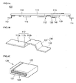
- FIG. 1A illustrates a side view of a protective circuit module in accordance with an embodiment
- FIG. 1B illustrates a perspective view of a negative terminal tab in the protective circuit module of FIG. 1A ;
- FIG. 1C illustrates a perspective view of a chip-type PTC device in the protective circuit module of FIG. 1A ;
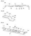
- FIG. 2A illustrates a side view of a protective circuit module in accordance with another embodiment
- FIG. 2B illustrates a perspective view of a negative terminal tab in the protective circuit module of FIG. 2A ;
- FIG. 2C illustrates a perspective view of a protective circuit module of FIG. 2A in a reversed state
- FIG. 3 illustrates a perspective view of a protective circuit module, which is not part of the present invention
- FIG. 4 illustrates a perspective view of a protective circuit module which is not part of the present invention.
- FIG. 5 illustrates an exploded perspective view of a rechargeable battery having a protective circuit module in accordance with an embodiment.
- FIG. 1A illustrates a side view of a protective circuit module in accordance with an embodiment.
- FIG. 1B illustrates a perspective view of a negative terminal tab in the protective circuit module of FIG. 1A.
- FIG. 1C illustrates a perspective view of a chip-type PTC device in the protective circuit module of FIG. 1A .
- a protective circuit module 100 in accordance with an embodiment may include a circuit board main body 110, a chip-type positive temperature coefficient (PTC) device 120 on the circuit board main body 110 and a heat transfer member 130 between the chip-type PTC device 120 and a heat-generating part of a bare cell (not shown). Further, the main protective circuit module 100 may include a negative terminal tab 112 connected to a negative terminal (not shown), which may also be a heat-generating part of the bare cell.
- PTC positive temperature coefficient
- the circuit board main body 110 may include a hole 111 generally at the center thereof.
- the negative terminal tab 112 may be attached to a lower part of the hole 111 of the circuit board main body 110.
- the negative terminal tab 112 may be electrically connected to the negative terminal of the bare cell.
- Positive terminal tabs 113 and 114 may be attached to lower surfaces of right and left ends of the circuit board main body 110. At least one of the positive terminal tabs 113 and 114 may be electrically connected to the positive terminal of the bare cell.
- An upper surface of the circuit board main body 110 may include several external terminals 115 for transfer of electric current from the battery to the outside.
- a lower surface of the circuit board main body 110 may include several protective circuit devices 116.
- the negative terminal tab 112 may include a terminal-fixing part 112a electrically connected to the negative terminal of the bare cell and a circuit board-fixing part 112b formed integrally with the terminal-fixing part 112a.
- the circuit board-fixing part 112b may be fixed to the circuit board main body 110.
- the terminal-fixing part 112a may have a rectangular plate-shape. This plate-shaped terminal-fixing part 112a may be substantially parallel to the negative terminal of the bare cell. When it is welded to the negative terminal of the bare cell, the terminal-fixing part 112a may be flexibly welded. Therefore, the terminal-fixing part 112a may be elastically welded to the negative terminal of the bare cell.
- This configuration may advantageously support a connection between the terminal-fixing part 112a and the negative terminal, even when the circuit board main body 110 is bent.
- the circuit board-fixing part 112b may be bent away from an end of the terminal-fixing part 112a and may have a rectangular plate-shape to make close contact with a lower surface of the circuit board main body 110.
- the terminal-fixing part 112a and the circuit board-fixing part 112b may be integrally connected to each other by a connecting portion 112c.
- the negative terminal tab 112 may be formed integrally with the heat transfer member 130.
- the heat transfer member 130 may extend from an end of a circuit board-fixing part 112b of the negative terminal tab 112 to contact the chip-type PTC device 120.
- the heat transfer member 130 may include an electrically and thermally conductive material.
- the heat transfer member 130 may include a bending portion 131 fixed to a lower surface of the circuit board main body 110 and bent away from the circuit board-fixing part 112b.
- the heat transfer member 130 may also include a contact portion 132 extending from the bending portion 131 to contact an outer surface of the chip-type PTC device 120.
- the bending portion 131 of the heat transfer member 130 may be vertical or may be oblique at a predetermined angle of inclination. That is, the bending portion 131 may have a height that ensures that the contact portion 132 may contact a surface of the chip-type PTC device 120.
- the contact portion 132 may have a length and area sufficient to ensure contact with a surface of the chip-type PTC device 120.
- the heat transfer member 130 and the chip-type PTC device 120 may be attached to each other by an adhesive member 140. That is, the adhesive member 140 may connect the two members such that the contact portion 132 of the heat transfer member 130 is in contact with a surface of the chip-type PTC device 120.
- the adhesive member 140 is preferably a tape, and more preferably an insulating tape. However, there is no particular limit to the kinds of the adhesive member 140 that may be used.
- the chip-type PTC device 120 may include a PTC body 121 including a conductive polymer having PTC properties and first and second conductive portions 122 and 123 in the form of, e.g., metal foil, on upper and lower surfaces of the PTC body 121.
- the PTC body 121 may be prepared by dispersing conductive particles in crystalline polymers. When the battery is below a given temperature, the PTC body 121 may serve as a current-flow path between the first conductive portion 122 and the second conductive portion 123.
- the crystalline polymers When the battery is exposed to a high temperature above a predetermined temperature due to, e.g., overcurrent, the crystalline polymers may swell, leading to dissociation of the conductive particles dispersed in the crystalline polymers, which may bring about a rapid increase in resistance. As a result, electric current flow between the first conductive portion 122 and the second conductive portion 123 may be blocked or decreased. This may cut off the current flow from the bare cell to the external terminals 115.
- the PTC body 121 may serve a safety device for preventing, e.g., rupture of the battery. When the battery is then cooled below the predetermined temperature, the crystalline polymers of the PTC body 121 may shrink, which may lead to re-association of the conductive particles, reestablishing a smooth flow of electric current.
- a circuit board main body 110 of the protective circuit module 100 may be electrically connected to the bare cell by the PTC device 120, the heat transfer member 130 and the negative terminal tab 112 to the region of the hole 111. This may be accomplished by e.g., welding the same to a negative terminal of the bare cell.
- electric current from the negative terminal of the bare cell may flow to the external terminals 115 on the circuit board main body 110 through the negative terminal tab 112, the heat transfer member 130 and the chip-type PTC device 120.
- the chip-type PTC device 120 may receive electric current and heat through a heat transfer member 130, which may be formed integrally with the circuit board-fixing part 112b of the negative terminal tab 112.
- the chip-type PTC device 120 may directly detect heat from the negative terminal of the bare cell through the heat transfer member 130 formed integrally with the negative terminal tab 112. As a result, heat-detecting properties of the chip-type PTC device 120 may be significantly improved. Accordingly, overcurrent, which may produce heat, may result in a rapid increase of internal resistance in the PTC body 121 of the chip-type PTC device 120, so the flow of electric current between the first conductive portion 122 and the second conductive portion 123 may be prevented: The disconnection between the bare cell and the external terminals 115 cuts off heat generating charging/discharging operations of the battery. In this manner, rupture or ignition of the battery may be prevented by the chip-type PTC device 120.
- FIG. 2A illustrates a side view of a protective circuit module in accordance with another embodiment.
- FIG. 2B illustrates a perspective view of a negative terminal tab in the protective circuit module of FIG. 2A.
- FIG. 2C illustrates a perspective view of a protective circuit module of FIG. 2A in a reversed state.
- a protective circuit module 200 in accordance with another embodiment may include a circuit board main body 210, a chip-type PTC device 120 on the circuit board main body 210 and a heat transfer member 230 between the chip-type PTC device 120 and a heat-generating part of a bare cell (not shown). Further, the protective circuit module 200 may include a negative terminal tab 212 connected to a negative terminal (not shown), which may also be a heat-generating part of the bare cell.
- the circuit board main body 210 may have a hole 211 generally at the center thereof
- the negative terminal tab 212 may be attached to a lower part of the hole 211.
- Positive terminal tabs 113 and 114 on lower surfaces of right and left ends of the circuit board main body 210, external terminals 115 on an upper surface of the circuit board main body 210 and a protective circuit device 116 on a lower surface of the circuit board main body 210 may have the same configuration the previous embodiment.
- the negative terminal tab 212 may be formed integrally with the heat transfer member 230.
- the negative terminal tab 212 and the heat transfer member 230 may include a thermally and electrically conductive material.
- the integrally formed negative terminal tab 212 and heat transfer member 230 may electrically and thermally connect the bare cell with the chip-type PTC device 120.
- the negative terminal tab 212 may include a terminal-fixing part 212a connected to a negative terminal of the bare cell and a circuit board-fixing part 212b formed integrally with the terminal-fixing part 212a and fixed to the circuit board main body 210.
- the circuit board-fixing part 212b may have a rectangular plate-shape.
- the terminal-fixing part 212a may be bent concavely downward to have a U-shaped cross section such that it may be in contact with the negative terminal of the bare cell near the inside center of the circuit board-fixing part 212b.
- the heat transfer member 230 may extend from an end of a circuit board-fixing part 212b of the negative terminal tab 212 to contact the chip-type PTC device 120.
- the heat transfer member 230 may include a bending portion 231 fixed to a lower surface of the circuit board main body 210 and bent away from the circuit board-fixing part 212b.
- the heat transfer member 230 may also include a contact portion 232 extending from the bending portion 231 to contact an outer surface of the chip-type PTC device 120.
- the bending portion 231 of the heat transfer member 230 may be vertical or may be oblique at a predetermined angle of inclination. That is, the bending portion 231 may have a height that ensures that the contact portion 232 may contact a surface of the chip-type PTC device 120.
- the contact portion 232 may have a length and area sufficient to ensure contact with a surface of the chip-type PTC device 120.
- the heat transfer member 230 and the chip-type PTC device 120 may be attached to each other by the adhesive member 140.
- the chip-type PTC device 120 may have the same configuration as that of the previous embodiment, so repeated description thereof will be omitted.
- the protective circuit module 200 may be electrically connected to the bare cell such that the terminal-fixing part 212a of the negative terminal tab 212 may be welded to a negative terminal (not shown) of the bare cell.
- the terminal-fixing part 212a may have a generally U-shaped cross section and may bend concavely downward toward the negative terminal of the bare cell. As a result, the negative terminal of the bare cell may be stably supported by the terminal-fixing part 212a.
- electric current from the negative terminal of the bare cell may be transferred to the external terminals 115 on the circuit board main body 210 through the negative terminal tab 212, the heat transfer member 230 and the chip-type PTC device 120.
- the chip-type PTC device 120 may receive electric current and heat through the thermally and electrically conductive heat transfer member 230, which may be formed integrally with the negative terminal tab 212.
- the chip-type PTC device 120 may directly detect heat from the negative terminal of the bare cell through the heat transfer member 230. Accordingly, overcurrent, which may produce heat in the bare cell, may cause the internal resistance of the chip-type PTC device 120 to rapidly increase, thereby blocking the current flow between the bare cell and the external terminals 115, preventing, e.g., battery rupture or ignition. The disconnection between the bare cell and the external terminals 115 cuts off the heat generating charging/discharging operations of the battery.
- FIG. 3 illustrates a perspective view of a protective circuit module in a reversed state.
- a protective circuit module 300 may include a circuit board main body 210, a chip-type PTC device 120 on the circuit board main body 210 and a heat transfer member 330 between the chip-type PTC device 120 and a heat-generating part of a bare cell (not shown).
- the circuit board main body 210 and PTC device 120 may have the same configuration as that of the previous embodiment. Like numbers refer to like elements throughout the specification and drawings, so repeated description thereof will be omitted.
- the heat transfer member 330 may provide an electrical and thermal connection between the negative terminal tab 212 and the chip-type PTC device 120 on a lower surface of the circuit board main body 210. Therefore, the negative terminal tab 212 may be connected to a negative terminal (not shown) of the bare cell, so the chip-type PTC device 120 and the negative terminal of the bare cell may be connected to each other by the heat transfer member 330.
- the heat transfer member 330 and the external terminals 115 may be electrically connected by the chip-type PTC device 120.
- the heat transfer member 330 may include a heat transfer path.
- the heat transfer path may include a pattern (P) for electrically connecting the negative terminal tab 212 and the chip-type PTC device 120.
- a thermally conductive solder cream (S) may then be applied to an upper part of the pattern (P).
- the pattern (P) may function as a current flow path; and the solder cream (S) may serve as a heat transfer path, so heat-detecting performance of the chip-type PTC device 120 may be significantly improved.
- a wire solder or the like may be used for the heat transfer member 330.
- the heat transfer member 330 may extend from an end of the circuit board-fixing part 212b of the negative terminal tab 212 to the chip-type PTC device 120.
- the external terminals 115 of the protective circuit module 300 may be electrically connected to the bare cell by a terminal-fixing part 212a of the negative terminal tab 212 welded to a negative terminal (not shown) of the bare cell. Accordingly, electric current and heat from the negative terminal of the bare cell may flow through the negative terminal tab 212 to the chip-type PTC device 120 by a heat transfer member 330 electrically and thermally connected to the negative terminal tab 212.
- the chip-type PTC device 120 may directly detect heat from the negative terminal of the bare cell through the heat transfer member 330. Accordingly, overcurrent, which may produce heat in the battery, cuts off the current flow between the bare cell and the external terminals 115 to prevent, e.g., battery rupture or ignition.
- FIG. 4 illustrates a perspective view of a protective circuit module in a reversed state.
- the protective circuit module 400 may include a circuit board main body 210, a chip-type PTC device 120 on the circuit board main body 210, and a thermally and electrically conductive heat transfer member 430 between the chip-type PTC device 120 and a heat-generating part of a bare cell (not shown).
- the circuit board main body 210 and the chip-type PTC device 120 may have the same configuration as that of the previous embodiment. Like numbers refer to like elements throughout the specification and drawings, so repeated description thereof will be omitted.
- At least one of the positive terminal tabs 113 and 114 on lower surfaces of right and left ends of the circuit board main body 210 may be electrically and thermally connected to the chip-type PTC device 120 on a lower surface of the circuit board main body 210 by the heat transfer member 430.
- the positive terminal tabs 113 and 114 may be connected to a cap plate (not shown) which may function as a positive terminal of the bare cell. Therefore, the chip-type PTC device 120 may be electrically and thermally connected to a positive terminal that corresponds to a heat-generating part of the bare cell via the heat transfer member 430.
- At least one of the positive terminal tabs 113 and 114 may be electrically and thermally connected to the chip-type PTC device 120 by the heat transfer member 430. Although the chip-type PTC device 120 and the positive terminal tab 114 are connected in FIG. 4 , the other positive terminal tab 113 may also be connected to the chip-type PTC device 120.
- the heat transfer member 430 may include a heat transfer path.
- the heat transfer path may include a pattern (P) electrically connecting the positive terminal tab 114 and the chip-type PTC device 120.
- a thermally conductive solder cream (S) may then be applied to an upper part of the pattern (P).
- the pattern (P) may form a current flow path and the thermally conductive solder cream (S) may form a heat transfer path, so heat-detecting performance of the chip-type PTC device 120 may be significantly improved.
- a wire solder or the like may be used as the heat transfer member 430.
- the heat transfer member 430 may contact an end of the positive terminal tab 114 and the chip-type PTC device 120.
- the external terminals 115 of the protective circuit module 400 may be electrically connected to the bare cell by the negative terminal tab 212 welded to a negative terminal (not shown) of the bare cell.
- positive terminal tabs 113 and 114 on the lower surface of right and left ends of the circuit board main body 210 may be welded to an upper surface of a cap plate (not shown) of the bare cell and also electrically connected to the external terminals 115.
- the cap plate of the bare cell may correspond to a positive terminal of the bare cell, so the positive terminal tabs 113 and 114 may be electrically connected to the positive terminal of the bare cell.
- electric current and heat from the cap plate of the bare cell may be transferred to the heat transfer member 430 through the positive terminal tab 114 and may then be transferred to the chip-type PTC device 120 by the heat transfer member 430.
- the chip-type PTC device 120 may directly detect electric current and heat from the cap plate of the bare cell through the electrically and thermally conductive heat transfer member 430. Accordingly, overcurrent, which may produce heat in the battery, may rapidly increase the internal resistance of the chip-type PTC device 120, thereby blocking the current flow between the bare cell and the external terminals 115, thus preventing, e.g., battery rupture or ignition.
- FIG. 5 illustrates an exploded perspective view of a rechargeable battery having a protective circuit module in accordance an embodiment.
- a rechargeable battery 10 may include a bare cell 20 and a protective circuit module 100 electrically connected to the bare cell 20.
- the bare cell 20 may include a can 21, an electrode assembly 22 housed in the can 21 and a cap assembly 30 for sealing an open part 21a of the can 21.
- the can 21 may be a generally rectangular-shaped metal container which has an open part 21a at one end thereof and may be formed by a processing method, e.g., deep drawing. Therefore, the can 21 may also serve as a terminal.
- the can 21 is preferably formed of, e.g., an aluminum or aluminum alloy that is a light-weight conductive metal.
- the electrode assembly 22 may be prepared by stacking a positive electrode plate 23, a negative electrode plate 25 and a separator 24 disposed therebetween and winding the resulting stacked structure into a jelly roll shape.
- the positive electrode plate 23 may be formed by coating, e.g., lithium cobalt oxide (LiCoO 2 ) as a positive electrode active material on a current collector made of, e.g., aluminum.
- the negative electrode plate 25 maybe formed by coating, e.g., carbon, as a negative electrode active material on a current collector made of, e.g., copper.
- the separator 24 may be formed of, e.g., polyethylene, polypropylene or a copolymer thereof.
- a positive electrode tab 26 connected to the positive electrode plate 23 and a negative electrode tab 27 connected to the negative electrode plate 25 may be drawn upward from the electrode assembly 22.
- the interface region drawn outward from the electrode assembly 22 may be wound by an insulating tape 28.
- the cap assembly 30 may include a cap plate 31, a gasket 32, a negative terminal 33, an insulating plate 34, a terminal plate 35, an insulating case 36 and a plug 37.
- the cap plate 31 may include a terminal through-hole 31a generally at the center thereof.
- the gasket 32 may be positioned on the outer periphery of the negative terminal 33 and may then pass through the terminal through-hole 31a.
- a side of the cap plate 31 may include an electrolyte injection hole 31b. After injection of the electrolyte is complete, the electrolyte injection hole 31b may be sealed with a plug 27.
- the insulating plate 34 may be disposed below the cap plate 31; and a terminal plate 35 may be disposed below the insulating plate 34. Therefore, the insulating plate 34 may provide electrical insulation between the cap plate 31 and the terminal plate 35.
- the terminal plate 35 may be connected to a lower end of the negative terminal 33.
- the negative electrode plate 25 of the electrode assembly 22 may be electrically connected to the negative terminal 33 through the negative electrode tab 27 and the terminal plate 35. Further, the-positive electrode plate 23 of the electrode assembly 22 may be electrically connected to the cap plate 31 through the positive electrode tab 26. Therefore, the cap plate 31 may serve as a positive terminal.
- the insulating case 36 may be disposed on an upper part of the electrode assembly 22 to thereby prevent electrical connection between the electrode assembly 22 and the cap assembly 30.
- the protective circuit module 100 may include a circuit board main body 110, a chip-type PTC device 120 on the circuit board main body 110, external terminals 115 and an electrically and thermally conductive heat transfer member 130 between the chip-type PTC device 120 and the negative terminal 33 of the bare cell 20.
- the circuit board main body 110, chip-type PTC device 120 and heat transfer member 130 may have the same configuration as that of the protective circuit module 100 described above, so repeated description thereof will be omitted.
- the external terminals 115 of the protective circuit module 100 may be electrically connected to the bare cell by the PTC device 120, the heat transfer member 130, and the negative terminal tab 112. This may be accomplished by, e.g., laser-welding thereof, to a negative terminal 33 of the bare cell 20.
- positive terminal tabs 113 and 114 may be electrically connected to right and left sides of an upper surface of the cap plate 31 of the bare cell 20 by, e.g., a resistance welding method. Therefore, the cap plate 31 may serve as a positive terminal.
- Electric current from the negative terminal 33 of the bare cell may flow to the external terminals 115 of the circuit board main body 110 through the negative terminal tab 112, the heat transfer member 130 formed integrally with the negative terminal tab 112 and the chip-type PTC device 120. That is, the chip-type PTC device 120 may directly receive heat and electric current from the bare cell through the electrically and thermally conductive heat transfer member 130.
- the chip-type PTC device 120 may block the flow of electric current, cutting off heat generating charging/discharging operations, thereby serving as a safety device that may prevent, e.g., rupture of the battery.
- the conductive particles of the chip-type PTC device 120 may recombine, thus reestablishing a normal flow of electric current.
- an electrically and thermally conductive heat transfer member is provided between the chip-type PTC device and the bare cell, such that the chip-type PTC device may directly detect temperature changes in the bare cell.
- This heat transfer path is provided by being integrally formed either with a negative terminal tab or a positive terminal tab typically installed in the protective circuit-module. Such approaches may enable reduction of production costs and simplification of production processes.
Landscapes
- Chemical & Material Sciences (AREA)
- Chemical Kinetics & Catalysis (AREA)
- Electrochemistry (AREA)
- General Chemical & Material Sciences (AREA)
- Engineering & Computer Science (AREA)
- Manufacturing & Machinery (AREA)
- Microelectronics & Electronic Packaging (AREA)
- Materials Engineering (AREA)
- Connection Of Batteries Or Terminals (AREA)
- Battery Mounting, Suspending (AREA)
- Sealing Battery Cases Or Jackets (AREA)
Claims (11)
- Schutzschaltungsmodul (100, 200), umfassend:einen Schaltungsplattenhauptkörper (110, 210) mit einem Elektrodenklemmenstreifen (112, 212), der so ausgestaltet ist, dass er mit einer Elektrodenklemme (33) einer blanken Zelle (20) direkt elektrisch verbunden ist;eine Vorrichtung mit positivem Temperaturkoeffizienten (120) auf dem Schaltungsplattenhauptkörper (110, 210); undein Wärmeübertragungselement (130, 230), das mit der Vorrichtung mit positivem Temperaturkoeffizienten (120) und mit dem Elektrodenklemmenstreifen (112, 212) verbunden i st, unddadurch gekennzeichnet, dassdas Wärmeübertragungselement (130, 230) und der Elektrodenklemmenstreifen (112, 212) als ein einziger Körper ausgebildet sind undder Elektrodenklemmenstreifen (112, 212) einschließt: einen Klemmenbefestigungsteil (112a, 212a), der so ausgestaltet ist, dass er mit der Elektrodenklemme (33) der blanken Zelle (20) verbunden ist, und einen Schaltungsplattenbefestigungsteil (112b, 212b), der als ein einziger Körper mit dem Klemmenbefestigungsteil (112a, 212a) ausgebildet und an dem Schaltungsplattenhauptkörper (110, 210) befestigt ist.
- Schutzschaltungsmodul (100, 200, 300, 400) nach Anspruch 1, wobei die Vorrichtung mit positivem Temperaturkoeffizienten (120) eine Vorrichtung mit positivem Temperaturkoeffizienten (120) in der Art eines Chips ist
und/oder eine der folgenden Bedingungen (1) und (ii) erfüllt ist:(i) der Elektrodenklemmenstreifen (112, 113, 114, 212) ist ein Minusklemmenstreifen (112, 212), der so angepasst ist, dass er mit einer Minusklemme (33) der blanken Zelle (20) elektrisch verbunden ist,(ii) der Elektrodenklemmenstreifen (112, 113, 114, 212) ist ein Plusklemmenstreifen (113, 114), der so angepasst ist, dass er mit einer Plusklemme (3 1) der blanken Zelle (20) elektrisch verbunden ist. - Schutzschaltungsmodul (100, 200) nach einem der Ansprüche 1 und 2,
wobei der Klemmenbefestigungsteil (1 12a) von dem Schaltungsplattenbefestigungsteil (112b) weg gebogen ist und so ausgestaltet ist, dass er im Wesentlichen parallel zur Elektrodenklemme (33) der blanken Zelle (20) ist,
oder
wobei der Klemmenbefestigungsteil (212a) konkav von dem Schaltungsplattenbefestigungsteil (212b) weg gebogen ist und so ausgestaltet ist, dass er die Elektrodenklemme (33) der blanken Zelle (20) kontaktiert. - Schutzschaltungsmodul (100, 200) nach einem der vorangehenden Ansprüche, wobei das Wärmeübertragungselement (130, 230) einschließt: einen Biegeabschnitt (131, 231) und einen Kontaktabschnitt (132, 232), der sich von dem Biegeabschnitt (131, 231) erstreckt und die Vorrichtung mit positivem Temperaturkoeffizienten (120) kontaktiert.
- Schutzschaltungsmodul (100, 200) nach Anspruch 4, wobei der Biegeabschnitt (131, 231) mit dem Elektrodenklemmenstreifen (112, 212) verbunden ist.
- Schutzschaltungsmodul (100, 200) nach einem der vorangehenden Ansprüche, ferner umfassend: ein Haftelement (140), welches das Wärmeübertragungselement (130, 230) mit der Vorrichtung mit positivem Temperaturkoeffizienten (120) verbindet.
- Schutzschaltungsmodul (100, 200) nach Anspruch 6, wobei das Haftelement (140) ein Isolierband ist.
- Schutzschaltungsmodul (100, 200, 300, 400) nach einem der vorangehenden Ansprüche, wobei die Vorrichtung mit positivem Temperaturkoeffizienten (120) einschließt:einen Körper mit positivem Temperaturkoeffizienten (121) mit oberen und unteren Oberflächen, ein leitendes Polymer mit positiven Temperaturkoeffizienteneigenschaften, einen ersten leitenden Abschnitt (122) und einen zweiten leitenden Abschnitt (123), wobei der erste leitende Abschnitt (122) und der zweite leitende Abschnitt (123) Metallfolie auf den oberen undunteren Oberflächen des Körpers mit positivem Temperaturkoeffizienten (121) einschließen.
- Wiederaufladbare Batterie (10), umfassend:eine blanke Zelle (20); undein Schutzschaltungsmodul (100, 200, 300, 400) nach einem der Ansprüche 1 bis 8,wobei das Schutzschaltungsmodul (100, 200, 300, 400) mit der blanken Zelle (20) elektrisch verbunden ist,wobei das Schutzschaltungsmodul (100, 200, 300, 400) einschließt: einen Schaltungsplattenhauptkörper (110, 210), eine Vorrichtung mit positivem Temperaturkoeffizienten (120) auf dem Schaltungsplattenhauptkörper (110, 210), einen Elektrodenklemmenstreifen (112, 114, 212), der mit der blanken Zelle (20) elektrisch verbunden ist, und ein Wärmeübertragungselement (130, 230, 330, 430), das die Vorrichtung mit positivem Temperaturkoeffizienten (120) und den Elektrodenklemmenstreifen (112, 114, 212) elektrisch verbindet.
- Wiederaufladbare Batterie (10) nach Anspruch 9,
wobei die blanke Zelle (20) eine Minusklemme (33) einschließt und das Wärmeübertragungselement (130, 230, 330) durch den Elektrodenklemmenstreifen (112, 212) mit der Minusklemme (33) verbunden ist
oder
wobei die blanke Zelle (20) eine Plusklemme (31) einschließt und das Wärmeübertragungselement (430) durch den Elektrodenklemmenstreifen (114) mit der Plusklemme (31) verbunden ist. - Wiederaufladbare Batterie nach Anspruch 10, wobei die Plusklemme (31) eine Deckelplatte der blanken Zelle (20) ist.
Applications Claiming Priority (1)
| Application Number | Priority Date | Filing Date | Title |
|---|---|---|---|
| KR1020080103639A KR101023874B1 (ko) | 2008-10-22 | 2008-10-22 | 보호회로모듈 및 보호회로모듈을 포함하는 이차전지 |
Publications (2)
| Publication Number | Publication Date |
|---|---|
| EP2180538A1 EP2180538A1 (de) | 2010-04-28 |
| EP2180538B1 true EP2180538B1 (de) | 2012-06-06 |
Family
ID=41395011
Family Applications (1)
| Application Number | Title | Priority Date | Filing Date |
|---|---|---|---|
| EP09173635A Not-in-force EP2180538B1 (de) | 2008-10-22 | 2009-10-21 | Schutzschaltungsmodul und wiederaufladbare Batterie damit |
Country Status (5)
| Country | Link |
|---|---|
| US (1) | US8883331B2 (de) |
| EP (1) | EP2180538B1 (de) |
| JP (1) | JP5135315B2 (de) |
| KR (1) | KR101023874B1 (de) |
| CN (1) | CN101728583B (de) |
Families Citing this family (22)
| Publication number | Priority date | Publication date | Assignee | Title |
|---|---|---|---|---|
| DE102009029093A1 (de) * | 2009-09-02 | 2011-03-03 | Robert Bosch Gmbh | Verfahren zum Erwärmen eines Akkumulators, Ladegerät und Zusatzelement |
| US9099726B2 (en) | 2010-01-19 | 2015-08-04 | Samsung Sdi Co., Ltd. | Secondary battery and method of fabricating the same |
| KR101274839B1 (ko) * | 2010-07-26 | 2013-06-13 | 삼성에스디아이 주식회사 | 리드 플레이트를 통해 배어셀의 열을 온도 감응 소자에 전달하는 이차 전지 |
| KR101192042B1 (ko) | 2010-11-01 | 2012-10-17 | 삼성에스디아이 주식회사 | 배터리 팩 |
| KR101201069B1 (ko) | 2010-11-12 | 2012-11-14 | 삼성에스디아이 주식회사 | 배터리 팩 |
| KR101432224B1 (ko) * | 2012-02-07 | 2014-08-26 | 주식회사 엘지화학 | 신규한 구조의 내장형 이차전지 팩 |
| US9093723B2 (en) | 2012-06-08 | 2015-07-28 | Samsung Sdi Co., Ltd. | Rechargeable battery |
| KR101411584B1 (ko) * | 2013-04-12 | 2014-06-24 | 김영대 | 배터리 보호 장치 제조 방법 및 배터리 보호 장치 |
| EP2822063B1 (de) | 2013-07-01 | 2017-05-31 | Samsung SDI Co., Ltd. | Schutzvorrichtung für ein Batteriepack und Verfahren zur Herstellung der Schutzvorrichtung |
| KR102030110B1 (ko) | 2013-08-30 | 2019-11-08 | 삼성에스디아이 주식회사 | 이차 전지 |
| US9435581B2 (en) | 2014-03-26 | 2016-09-06 | Whirlpool Corporation | Interactive lighting in a refrigerator |
| EP3161897B1 (de) * | 2014-06-30 | 2020-03-11 | BYD Company Limited | Batteriemodul und signalerfassungseinheit davon |
| KR102295367B1 (ko) | 2014-12-08 | 2021-08-31 | 삼성에스디아이 주식회사 | 리튬이차전지용 복합 세퍼레이터 및 이를 채용한 리튬이차전지 |
| KR102442187B1 (ko) | 2015-04-10 | 2022-09-07 | 삼성에스디아이 주식회사 | 배터리 보호 회로 |
| KR102537226B1 (ko) | 2015-12-23 | 2023-05-26 | 삼성에스디아이 주식회사 | 이차전지 |
| KR102357835B1 (ko) * | 2017-01-26 | 2022-02-04 | 삼성에스디아이 주식회사 | 배터리 팩 |
| CN110120557B (zh) * | 2018-02-05 | 2021-01-15 | 宁德新能源科技有限公司 | 保护装置及电池 |
| EP3595078A1 (de) | 2018-07-12 | 2020-01-15 | Nederlandse Organisatie voor toegepast- natuurwetenschappelijk onderzoek TNO | Elektrode zur verwendung in einer geschichteten vorrichtungsstruktur sowie batterievorrichtung |
| CN111477966B (zh) * | 2019-01-23 | 2021-11-23 | 北京小米移动软件有限公司 | 终端电池保护板、终端电池及终端 |
| KR102640844B1 (ko) * | 2020-04-14 | 2024-02-27 | 삼성에스디아이 주식회사 | 배터리 팩 |
| JP7074798B2 (ja) * | 2020-05-18 | 2022-05-24 | 矢崎総業株式会社 | 回路接続モジュール |
| US11715851B2 (en) | 2020-06-17 | 2023-08-01 | Samsung Sdi Co., Ltd. | Battery module and vehicle including the same |
Family Cites Families (18)
| Publication number | Priority date | Publication date | Assignee | Title |
|---|---|---|---|---|
| CN1097830C (zh) * | 1995-08-07 | 2003-01-01 | 株式会社雷伊化学 | Ptc器件和使用它的电池组 |
| JP2000188205A (ja) * | 1998-10-16 | 2000-07-04 | Matsushita Electric Ind Co Ltd | チップ形ptcサ―ミスタ |
| JP4904614B2 (ja) * | 2000-06-22 | 2012-03-28 | パナソニック株式会社 | 電池パックおよびその製造方法 |
| DE10100142A1 (de) | 2000-08-21 | 2002-03-07 | Orient Semiconductor Elect Ltd | Kühlanordnung für Flip-Chip-Modul |
| EP1422771A4 (de) * | 2001-08-07 | 2009-01-21 | Panasonic Corp | Sekundärbatterie mit wasserfreiem elektrolyt |
| JP3836415B2 (ja) * | 2002-09-30 | 2006-10-25 | 京セラ株式会社 | バッテリー |
| KR100601533B1 (ko) * | 2004-07-28 | 2006-07-19 | 삼성에스디아이 주식회사 | 이차전지용 이차보호소자 |
| KR100731462B1 (ko) * | 2005-05-04 | 2007-06-21 | 삼성에스디아이 주식회사 | 이차전지 |
| KR100670501B1 (ko) * | 2005-05-04 | 2007-01-16 | 삼성에스디아이 주식회사 | 이차전지 |
| JP5270154B2 (ja) * | 2005-05-16 | 2013-08-21 | タイコエレクトロニクスジャパン合同会社 | 封口体 |
| KR100760784B1 (ko) * | 2006-07-04 | 2007-09-20 | 삼성에스디아이 주식회사 | 이차 전지용 보호회로모듈 및 이를 이용한 전지 팩 |
| KR100821857B1 (ko) | 2006-10-23 | 2008-04-15 | 주식회사 엘지화학 | 이차전지 팩 |
| KR100770106B1 (ko) | 2006-10-24 | 2007-10-24 | 삼성에스디아이 주식회사 | 리튬 이차 전지 |
| TW200843592A (en) * | 2007-04-16 | 2008-11-01 | Polytronics Technology Corp | Protective circuit board and over-current protection device thereof |
| KR100928131B1 (ko) * | 2007-11-08 | 2009-11-25 | 삼성에스디아이 주식회사 | Ptc 소자, ptc 소자를 포함하는 보호회로기판 및보호회로기판을 포함하는 이차전지 |
| JP5258027B2 (ja) | 2008-06-16 | 2013-08-07 | 日立マクセル株式会社 | 電池パック |
| JP5305748B2 (ja) | 2008-06-18 | 2013-10-02 | 三洋電機株式会社 | パック電池 |
| US8632910B2 (en) | 2008-09-03 | 2014-01-21 | Samsung Sdi Co., Ltd. | Protection circuit board, secondary battery and battery pack |
-
2008
- 2008-10-22 KR KR1020080103639A patent/KR101023874B1/ko not_active Expired - Fee Related
-
2009
- 2009-10-21 EP EP09173635A patent/EP2180538B1/de not_active Not-in-force
- 2009-10-22 JP JP2009243296A patent/JP5135315B2/ja not_active Expired - Fee Related
- 2009-10-22 US US12/588,633 patent/US8883331B2/en not_active Expired - Fee Related
- 2009-10-22 CN CN2009102072588A patent/CN101728583B/zh not_active Expired - Fee Related
Also Published As
| Publication number | Publication date |
|---|---|
| JP5135315B2 (ja) | 2013-02-06 |
| KR20100044487A (ko) | 2010-04-30 |
| KR101023874B1 (ko) | 2011-03-22 |
| EP2180538A1 (de) | 2010-04-28 |
| US20100098974A1 (en) | 2010-04-22 |
| JP2010103113A (ja) | 2010-05-06 |
| CN101728583A (zh) | 2010-06-09 |
| CN101728583B (zh) | 2013-06-05 |
| US8883331B2 (en) | 2014-11-11 |
Similar Documents
| Publication | Publication Date | Title |
|---|---|---|
| EP2180538B1 (de) | Schutzschaltungsmodul und wiederaufladbare Batterie damit | |
| EP2372808B1 (de) | Sekundärbatterie mit einer Sicherung | |
| US8632910B2 (en) | Protection circuit board, secondary battery and battery pack | |
| US8632900B2 (en) | Secondary battery | |
| KR100477750B1 (ko) | 리튬 이온 전지의 전극조립체 및 이를 이용한 리튬이온 전지 | |
| JP4579880B2 (ja) | 二次電池 | |
| JP5286244B2 (ja) | 保護回路基板、二次電池及び電池パック | |
| KR100938896B1 (ko) | 배터리 팩 | |
| CN100474663C (zh) | 可再充电电池 | |
| KR19990078101A (ko) | 방폭형이차전지 | |
| KR20180090100A (ko) | 과충전시 안전성 확보를 위한 단락 구조물 및 이를 포함하는 파우치형 이차전지 | |
| KR101016849B1 (ko) | 이차전지 | |
| KR100516772B1 (ko) | 전극탭을 캔의 단변부에 위치시킨 이차전지 | |
| KR20090098522A (ko) | 이차 전지 | |
| KR100502354B1 (ko) | 파우치형 리튬 이차 전지 | |
| KR20260053919A (ko) | 보호회로모듈, 이를 포함하는 배터리 어셈블리 및 배터리 어셈블리 제조 방법 | |
| KR101023850B1 (ko) | 이차전지용 이차보호소자 |
Legal Events
| Date | Code | Title | Description |
|---|---|---|---|
| PUAI | Public reference made under article 153(3) epc to a published international application that has entered the european phase |
Free format text: ORIGINAL CODE: 0009012 |
|
| 17P | Request for examination filed |
Effective date: 20091021 |
|
| AK | Designated contracting states |
Kind code of ref document: A1 Designated state(s): AT BE BG CH CY CZ DE DK EE ES FI FR GB GR HR HU IE IS IT LI LT LU LV MC MK MT NL NO PL PT RO SE SI SK SM TR |
|
| 17Q | First examination report despatched |
Effective date: 20100512 |
|
| RIC1 | Information provided on ipc code assigned before grant |
Ipc: H01M 10/42 20060101ALI20111019BHEP Ipc: H01M 2/04 20060101AFI20111019BHEP |
|
| GRAP | Despatch of communication of intention to grant a patent |
Free format text: ORIGINAL CODE: EPIDOSNIGR1 |
|
| GRAS | Grant fee paid |
Free format text: ORIGINAL CODE: EPIDOSNIGR3 |
|
| GRAA | (expected) grant |
Free format text: ORIGINAL CODE: 0009210 |
|
| AK | Designated contracting states |
Kind code of ref document: B1 Designated state(s): AT BE BG CH CY CZ DE DK EE ES FI FR GB GR HR HU IE IS IT LI LT LU LV MC MK MT NL NO PL PT RO SE SI SK SM TR |
|
| REG | Reference to a national code |
Ref country code: GB Ref legal event code: FG4D |
|
| REG | Reference to a national code |
Ref country code: AT Ref legal event code: REF Ref document number: 561398 Country of ref document: AT Kind code of ref document: T Effective date: 20120615 Ref country code: CH Ref legal event code: EP |
|
| REG | Reference to a national code |
Ref country code: IE Ref legal event code: FG4D |
|
| REG | Reference to a national code |
Ref country code: DE Ref legal event code: R096 Ref document number: 602009007445 Country of ref document: DE Effective date: 20120802 |
|
| REG | Reference to a national code |
Ref country code: NL Ref legal event code: VDEP Effective date: 20120606 |
|
| PG25 | Lapsed in a contracting state [announced via postgrant information from national office to epo] |
Ref country code: SE Free format text: LAPSE BECAUSE OF FAILURE TO SUBMIT A TRANSLATION OF THE DESCRIPTION OR TO PAY THE FEE WITHIN THE PRESCRIBED TIME-LIMIT Effective date: 20120606 Ref country code: CY Free format text: LAPSE BECAUSE OF FAILURE TO SUBMIT A TRANSLATION OF THE DESCRIPTION OR TO PAY THE FEE WITHIN THE PRESCRIBED TIME-LIMIT Effective date: 20120606 Ref country code: LT Free format text: LAPSE BECAUSE OF FAILURE TO SUBMIT A TRANSLATION OF THE DESCRIPTION OR TO PAY THE FEE WITHIN THE PRESCRIBED TIME-LIMIT Effective date: 20120606 Ref country code: FI Free format text: LAPSE BECAUSE OF FAILURE TO SUBMIT A TRANSLATION OF THE DESCRIPTION OR TO PAY THE FEE WITHIN THE PRESCRIBED TIME-LIMIT Effective date: 20120606 Ref country code: NO Free format text: LAPSE BECAUSE OF FAILURE TO SUBMIT A TRANSLATION OF THE DESCRIPTION OR TO PAY THE FEE WITHIN THE PRESCRIBED TIME-LIMIT Effective date: 20120906 |
|
| REG | Reference to a national code |
Ref country code: AT Ref legal event code: MK05 Ref document number: 561398 Country of ref document: AT Kind code of ref document: T Effective date: 20120606 |
|
| REG | Reference to a national code |
Ref country code: LT Ref legal event code: MG4D Effective date: 20120606 |
|
| PG25 | Lapsed in a contracting state [announced via postgrant information from national office to epo] |
Ref country code: HR Free format text: LAPSE BECAUSE OF FAILURE TO SUBMIT A TRANSLATION OF THE DESCRIPTION OR TO PAY THE FEE WITHIN THE PRESCRIBED TIME-LIMIT Effective date: 20120606 Ref country code: SI Free format text: LAPSE BECAUSE OF FAILURE TO SUBMIT A TRANSLATION OF THE DESCRIPTION OR TO PAY THE FEE WITHIN THE PRESCRIBED TIME-LIMIT Effective date: 20120606 Ref country code: GR Free format text: LAPSE BECAUSE OF FAILURE TO SUBMIT A TRANSLATION OF THE DESCRIPTION OR TO PAY THE FEE WITHIN THE PRESCRIBED TIME-LIMIT Effective date: 20120907 Ref country code: LV Free format text: LAPSE BECAUSE OF FAILURE TO SUBMIT A TRANSLATION OF THE DESCRIPTION OR TO PAY THE FEE WITHIN THE PRESCRIBED TIME-LIMIT Effective date: 20120606 |
|
| PG25 | Lapsed in a contracting state [announced via postgrant information from national office to epo] |
Ref country code: EE Free format text: LAPSE BECAUSE OF FAILURE TO SUBMIT A TRANSLATION OF THE DESCRIPTION OR TO PAY THE FEE WITHIN THE PRESCRIBED TIME-LIMIT Effective date: 20120606 Ref country code: SK Free format text: LAPSE BECAUSE OF FAILURE TO SUBMIT A TRANSLATION OF THE DESCRIPTION OR TO PAY THE FEE WITHIN THE PRESCRIBED TIME-LIMIT Effective date: 20120606 Ref country code: CZ Free format text: LAPSE BECAUSE OF FAILURE TO SUBMIT A TRANSLATION OF THE DESCRIPTION OR TO PAY THE FEE WITHIN THE PRESCRIBED TIME-LIMIT Effective date: 20120606 Ref country code: BE Free format text: LAPSE BECAUSE OF FAILURE TO SUBMIT A TRANSLATION OF THE DESCRIPTION OR TO PAY THE FEE WITHIN THE PRESCRIBED TIME-LIMIT Effective date: 20120606 Ref country code: AT Free format text: LAPSE BECAUSE OF FAILURE TO SUBMIT A TRANSLATION OF THE DESCRIPTION OR TO PAY THE FEE WITHIN THE PRESCRIBED TIME-LIMIT Effective date: 20120606 Ref country code: IS Free format text: LAPSE BECAUSE OF FAILURE TO SUBMIT A TRANSLATION OF THE DESCRIPTION OR TO PAY THE FEE WITHIN THE PRESCRIBED TIME-LIMIT Effective date: 20121006 Ref country code: NL Free format text: LAPSE BECAUSE OF FAILURE TO SUBMIT A TRANSLATION OF THE DESCRIPTION OR TO PAY THE FEE WITHIN THE PRESCRIBED TIME-LIMIT Effective date: 20120606 Ref country code: RO Free format text: LAPSE BECAUSE OF FAILURE TO SUBMIT A TRANSLATION OF THE DESCRIPTION OR TO PAY THE FEE WITHIN THE PRESCRIBED TIME-LIMIT Effective date: 20120606 |
|
| PG25 | Lapsed in a contracting state [announced via postgrant information from national office to epo] |
Ref country code: PT Free format text: LAPSE BECAUSE OF FAILURE TO SUBMIT A TRANSLATION OF THE DESCRIPTION OR TO PAY THE FEE WITHIN THE PRESCRIBED TIME-LIMIT Effective date: 20121008 Ref country code: IT Free format text: LAPSE BECAUSE OF FAILURE TO SUBMIT A TRANSLATION OF THE DESCRIPTION OR TO PAY THE FEE WITHIN THE PRESCRIBED TIME-LIMIT Effective date: 20120606 Ref country code: PL Free format text: LAPSE BECAUSE OF FAILURE TO SUBMIT A TRANSLATION OF THE DESCRIPTION OR TO PAY THE FEE WITHIN THE PRESCRIBED TIME-LIMIT Effective date: 20120606 |
|
| PLBE | No opposition filed within time limit |
Free format text: ORIGINAL CODE: 0009261 |
|
| STAA | Information on the status of an ep patent application or granted ep patent |
Free format text: STATUS: NO OPPOSITION FILED WITHIN TIME LIMIT |
|
| PG25 | Lapsed in a contracting state [announced via postgrant information from national office to epo] |
Ref country code: ES Free format text: LAPSE BECAUSE OF FAILURE TO SUBMIT A TRANSLATION OF THE DESCRIPTION OR TO PAY THE FEE WITHIN THE PRESCRIBED TIME-LIMIT Effective date: 20120917 Ref country code: DK Free format text: LAPSE BECAUSE OF FAILURE TO SUBMIT A TRANSLATION OF THE DESCRIPTION OR TO PAY THE FEE WITHIN THE PRESCRIBED TIME-LIMIT Effective date: 20120606 |
|
| 26N | No opposition filed |
Effective date: 20130307 |
|
| PG25 | Lapsed in a contracting state [announced via postgrant information from national office to epo] |
Ref country code: MC Free format text: LAPSE BECAUSE OF NON-PAYMENT OF DUE FEES Effective date: 20121031 |
|
| REG | Reference to a national code |
Ref country code: DE Ref legal event code: R097 Ref document number: 602009007445 Country of ref document: DE Effective date: 20130307 |
|
| REG | Reference to a national code |
Ref country code: IE Ref legal event code: MM4A |
|
| PG25 | Lapsed in a contracting state [announced via postgrant information from national office to epo] |
Ref country code: IE Free format text: LAPSE BECAUSE OF NON-PAYMENT OF DUE FEES Effective date: 20121021 Ref country code: BG Free format text: LAPSE BECAUSE OF FAILURE TO SUBMIT A TRANSLATION OF THE DESCRIPTION OR TO PAY THE FEE WITHIN THE PRESCRIBED TIME-LIMIT Effective date: 20120906 |
|
| PG25 | Lapsed in a contracting state [announced via postgrant information from national office to epo] |
Ref country code: MT Free format text: LAPSE BECAUSE OF FAILURE TO SUBMIT A TRANSLATION OF THE DESCRIPTION OR TO PAY THE FEE WITHIN THE PRESCRIBED TIME-LIMIT Effective date: 20120606 |
|
| PG25 | Lapsed in a contracting state [announced via postgrant information from national office to epo] |
Ref country code: TR Free format text: LAPSE BECAUSE OF FAILURE TO SUBMIT A TRANSLATION OF THE DESCRIPTION OR TO PAY THE FEE WITHIN THE PRESCRIBED TIME-LIMIT Effective date: 20120606 |
|
| PG25 | Lapsed in a contracting state [announced via postgrant information from national office to epo] |
Ref country code: LU Free format text: LAPSE BECAUSE OF NON-PAYMENT OF DUE FEES Effective date: 20121021 Ref country code: SM Free format text: LAPSE BECAUSE OF FAILURE TO SUBMIT A TRANSLATION OF THE DESCRIPTION OR TO PAY THE FEE WITHIN THE PRESCRIBED TIME-LIMIT Effective date: 20120606 |
|
| REG | Reference to a national code |
Ref country code: CH Ref legal event code: PL |
|
| PG25 | Lapsed in a contracting state [announced via postgrant information from national office to epo] |
Ref country code: HU Free format text: LAPSE BECAUSE OF FAILURE TO SUBMIT A TRANSLATION OF THE DESCRIPTION OR TO PAY THE FEE WITHIN THE PRESCRIBED TIME-LIMIT Effective date: 20091021 Ref country code: LI Free format text: LAPSE BECAUSE OF NON-PAYMENT OF DUE FEES Effective date: 20131031 Ref country code: CH Free format text: LAPSE BECAUSE OF NON-PAYMENT OF DUE FEES Effective date: 20131031 |
|
| PG25 | Lapsed in a contracting state [announced via postgrant information from national office to epo] |
Ref country code: MK Free format text: LAPSE BECAUSE OF FAILURE TO SUBMIT A TRANSLATION OF THE DESCRIPTION OR TO PAY THE FEE WITHIN THE PRESCRIBED TIME-LIMIT Effective date: 20120606 |
|
| REG | Reference to a national code |
Ref country code: FR Ref legal event code: PLFP Year of fee payment: 7 |
|
| PGFP | Annual fee paid to national office [announced via postgrant information from national office to epo] |
Ref country code: FR Payment date: 20150923 Year of fee payment: 7 |
|
| PGFP | Annual fee paid to national office [announced via postgrant information from national office to epo] |
Ref country code: GB Payment date: 20151021 Year of fee payment: 7 Ref country code: DE Payment date: 20151013 Year of fee payment: 7 |
|
| REG | Reference to a national code |
Ref country code: DE Ref legal event code: R119 Ref document number: 602009007445 Country of ref document: DE |
|
| GBPC | Gb: european patent ceased through non-payment of renewal fee |
Effective date: 20161021 |
|
| REG | Reference to a national code |
Ref country code: FR Ref legal event code: ST Effective date: 20170630 |
|
| PG25 | Lapsed in a contracting state [announced via postgrant information from national office to epo] |
Ref country code: DE Free format text: LAPSE BECAUSE OF NON-PAYMENT OF DUE FEES Effective date: 20170503 Ref country code: FR Free format text: LAPSE BECAUSE OF NON-PAYMENT OF DUE FEES Effective date: 20161102 Ref country code: GB Free format text: LAPSE BECAUSE OF NON-PAYMENT OF DUE FEES Effective date: 20161021 |