EP2180761A1 - Panneau d'affichage à électroluminescence organique et son procédé de fabrication - Google Patents
Panneau d'affichage à électroluminescence organique et son procédé de fabrication Download PDFInfo
- Publication number
- EP2180761A1 EP2180761A1 EP07792378A EP07792378A EP2180761A1 EP 2180761 A1 EP2180761 A1 EP 2180761A1 EP 07792378 A EP07792378 A EP 07792378A EP 07792378 A EP07792378 A EP 07792378A EP 2180761 A1 EP2180761 A1 EP 2180761A1
- Authority
- EP
- European Patent Office
- Prior art keywords
- moisture
- proof
- film
- proof substrate
- film moisture
- Prior art date
- Legal status (The legal status is an assumption and is not a legal conclusion. Google has not performed a legal analysis and makes no representation as to the accuracy of the status listed.)
- Granted
Links
Images








Classifications
-
- H—ELECTRICITY
- H10—SEMICONDUCTOR DEVICES; ELECTRIC SOLID-STATE DEVICES NOT OTHERWISE PROVIDED FOR
- H10K—ORGANIC ELECTRIC SOLID-STATE DEVICES
- H10K59/00—Integrated devices, or assemblies of multiple devices, comprising at least one organic light-emitting element covered by group H10K50/00
- H10K59/80—Constructional details
- H10K59/87—Passivation; Containers; Encapsulations
- H10K59/871—Self-supporting sealing arrangements
- H10K59/8722—Peripheral sealing arrangements, e.g. adhesives, sealants
-
- H—ELECTRICITY
- H10—SEMICONDUCTOR DEVICES; ELECTRIC SOLID-STATE DEVICES NOT OTHERWISE PROVIDED FOR
- H10K—ORGANIC ELECTRIC SOLID-STATE DEVICES
- H10K50/00—Organic light-emitting devices
- H10K50/80—Constructional details
- H10K50/84—Passivation; Containers; Encapsulations
- H10K50/841—Self-supporting sealing arrangements
-
- H—ELECTRICITY
- H10—SEMICONDUCTOR DEVICES; ELECTRIC SOLID-STATE DEVICES NOT OTHERWISE PROVIDED FOR
- H10K—ORGANIC ELECTRIC SOLID-STATE DEVICES
- H10K50/00—Organic light-emitting devices
- H10K50/80—Constructional details
- H10K50/84—Passivation; Containers; Encapsulations
- H10K50/842—Containers
- H10K50/8426—Peripheral sealing arrangements, e.g. adhesives, sealants
-
- H—ELECTRICITY
- H10—SEMICONDUCTOR DEVICES; ELECTRIC SOLID-STATE DEVICES NOT OTHERWISE PROVIDED FOR
- H10K—ORGANIC ELECTRIC SOLID-STATE DEVICES
- H10K59/00—Integrated devices, or assemblies of multiple devices, comprising at least one organic light-emitting element covered by group H10K50/00
- H10K59/80—Constructional details
- H10K59/87—Passivation; Containers; Encapsulations
- H10K59/871—Self-supporting sealing arrangements
Definitions
- the present invention relates to an organic electroluminescent display panel comprising a film moisture-proof substrate having a built-in organic electroluminescent element, and a manufacturing method thereof.
- EL light-emitting sheets used for a flat-surface backlight have been incapable of forming a light-emitting surface of a curved shaped with the sheet shape as is, requiring a portion of the curved surface to be finished as a flat surface.
- a thin curved-surface light-emitting panel that uses an EL light-emitting sheet and its manufacturing method employ a method of using a frame to support the end portions of the EL light-emitting sheet to prevent shrinkage on curing in an attempt to correct the EL light-emitting sheet to a predetermined shape (see Patent document 1).
- shape changes such as warping are prevented from occurring on a thin curved-surface light-emitting panel that uses the EL light-emitting sheet, to the extent possible, thereby preventing the occurrence of non-uniform brightness.
- an organic electroluminescent display panel comprising: a frame body on which a desired reference surface is formed; a film moisture-proof substrate having a built-in thin-film organic electroluminescent element group; and a moisture-proof fixing member that fixes a front surface of the film moisture-proof substrate to the frame body while the front surface of the film moisture-proof substrate is in close contact with the reference surface, and covers at least an end portion of the film moisture-proof substrate.
- a manufacturing method of an organic electroluminescent display panel comprising the steps of: a step for fixing a front surface of a film moisture-proof substrate having a built-in thin-film organic electroluminescent element group to a frame body while in close contact with a reference surface formed on the frame body using a moisture-proof fixing member, while covering at least an end portion of the film moisture-proof substrate with the moisture-proof fixing member.
- FIG. 1 is a perspective view illustrating a configuration example of an organic electroluminescent display panel 1 of embodiment 1.
- the organic electroluminescent display panel 1 in appearance comprises a frame body 3 and a film moisture-proof substrate 7.
- organic electroluminescent display panel is abbreviated as “organic EL display panel.”
- This film moisture-proof substrate 7 comprises multiple rows of built-in thin-film organic electroluminescent elements, for example.
- the frame body 3 is an external member constituting a housing of the organic EL display panel 1. On the front surface of this frame body 3 is formed an opening, and this opening comprises a display surface 7a of the film moisture-proof substrate 7. That is, when the film moisture-proof substrate 7 is actuated, light is emitted from the display surface 7a by the action of the distributed organic electroluminescent elements, and a predetermined image is displayed.
- FIG. 2 is an exploded perspective view illustrating a configuration example of the organic EL display panel 1 of FIG. 1 , as assembled.
- the organic EL display panel 1 is disassembled with the display surface 7a facing downward as an example, illustrating a simplified view that focuses on the members related to the embodiment. Note that, in FIG. 2 , the organic EL display panel 1 may be disassembled with the display surface 7a facing upward.
- the organic EL display panel 1 mainly comprises the frame body 3 and the substrate 7.
- This substrate 7 is a moisture-proof substrate that is a film having multiple rows of organic electroluminescent elements as described above and is sealed by a resin such as plastic.
- the substrate 7 is referred to as the "film moisture-proof substrate 7.”
- This film moisture-proof substrate 7 is equivalent to a film moisture-proof substrate and has a built-in group of thin-film organic electroluminescent elements.
- the frame body 3 is formed into a thin box shape having an opening on the bottom, for example, and the display surface 7a of the film moisture-proof substrate 7 is exposed from this opening. That is, the frame body 3 comprises a side portion 3c that forms four surfaces along the thickness direction of organic EL display panel 1, and a frame portion 3b of a predetermined thickness that is formed along the outer edge of the organic EL display panel 1 when viewed from the display surface 7a.
- a reference surface 3a having a function such as described below is formed on the surface on the backside of the front surface (hereinafter "rear surface") of the frame portion 3b. This reference surface 3a presses against the film moisture-proof substrate 7 when the organic EL display panel 1 is assembled, and is used as a reference for correcting the film moisture-proof substrate 7 to a desired shape.
- FIG. 3 is a partial cross-sectional view showing an example of the film moisture-proof substrate 7 fixed to the frame body 3 of FIG. 2 .
- This film moisture-proof substrate 7 is fixed to the frame body 3 by a moisture-proof adhesive 6 (equivalent to a moisture-proof fixing member), with the front surface of the film moisture-proof substrate 7 in close contact with the reference surface 3a.
- This moisture-proof adhesive 6 covers the end portions of the film moisture-proof substrate 7.
- the "end portions of the film moisture-proof substrate 7" include not only the end surfaces that constitute the thickness of the film moisture-proof substrate 7, but also a part of the surrounding front and rear surfaces of the film moisture-proof substrate 7.
- the moisture-proof adhesive 6 is an adhesive for securing the film moisture-proof substrate 7 to the frame body 3 with the film moisture-proof substrate 7 in close contact with the reference surface, for example.
- the film moisture-proof substrate 7 is disposed so that the outer edge portions of the four sides thereof are in close contact with the reference surface 3a provided on the rear surface of the four sides of the frame body 3.
- the film moisture-proof substrate 7 is fixed to the frame body 3 by the moisture-proof adhesive 6 at fixing locations of the frame body 3.
- the moisture-proof adhesive 6 is made of a moisture-proof material, and has characteristics such as described later.
- the distributed electroluminescent element is generally an inorganic material, for example, the required moisture-proof function differs from that of the organic electroluminescent element.
- the moisture permeability of general resin is approximately 1 to 10 [g/m 2 per day]
- the moisture permeability of a resin substrate for an LCD (liquid crystal display) having an added moisture-proof barrier film is approximately 0.1 [g/m 2 per day] or less.
- the moisture permeability required in a thin-film organic electroluminescent element susceptible to humidity, moisture, and oxygen requires a high moisture-proof capability of an even lower numerical value, such as that equivalent to the measurement threshold of the Mocon method, i.e., approximately 0.001 [g/m 2 per day (g/m 2 per d)] or less.
- the moisture permeability (gas barrier characteristics) of a glass substrate is approximately 10 -3 to 10 -6 (g/m 2 per day).
- an acrylic UV curing adhesive is employed as the above-described moisture-proof adhesive 6, for example, and the moisture permeability of the end portions of the film moisture-proof substrate 7 sealed by this moisture-proof adhesive is 10 -3 [g/m 2 per day (g/m 2 per d)] or less, for example.
- the moisture-proof adhesive 6 is not limited to such an acrylic UV curing resin (adhesive), allowing use of resins (adhesives), such as an acrylic or epoxy, that cure by means such as ultraviolet light or heat.
- the moisture-proof adhesive 6 employs a joining material such as an epoxy
- the joining material is a member through which ultraviolet light passes, for example.
- a fixing frame 9, etc. is also made of a material that does not block the transmission of ultraviolet light, for example. Examples of material of the fixing frame 9 include plastic and metal.
- the locations covered and fixed by the moisture-proof adhesive 6 may be a fraction thereof.
- trim refers to the width from the moisture-proof substrate end portion to a component member such as the organic functional layer or organic insulating film of the organic EL susceptible to moisture or oxygen.
- the film moisture-proof substrate 7 exhibits a correction effect of being corrected to a desired shape that conforms to the reference surface 3a.
- the moisture-proof adhesive 6 since the moisture-proof adhesive 6 has moisture-proof characteristics as described above, the moisture-proof adhesive 6 exhibits a moisture-proof effect capable of effectively blocking off the thin-film organic electroluminescent elements susceptible to humidity and moisture from humidity, moisture, and oxygen.
- this moisture-proof adhesive 6 exhibits an anti-stripping effect capable of preventing a portion thereof from being stripped from the end portions of the film moisture-proof substrate 7.
- FIG. 4 is a partial cross-sectional view illustrating an alternative embodiment of the film moisture-proof substrate 7 fixed to the frame body 3 of FIG. 3 .
- a reference point 3d is formed on the rear surface of the frame body 3. Note that this reference point 3d may not only be formed into a point shape, but may also be formed into a linear shape, either partially or fully along the frame portion 3b on the rear surface thereof, for example.
- the front surface of the film moisture-proof substrate 7 having the built-in thin-film organic electroluminescent element group is fixed to the frame body 3 while in close contact with the reference surface 3a formed on the frame body 3 using the moisture-proof fixing member 6, while covering the end portions of the film moisture-proof substrate 7 with the moisture-proof fixing member 6.
- the organic EL display panel 1 of the above embodiment comprises the frame body 3 on which the desired reference surface 3a is formed, the film moisture-proof substrate 7 having the built-in thin-film organic electroluminescent element group, and the moisture-proof fixing member 6 that fixes the front surface of the film moisture-proof substrate 7, which is positioned in close contact with the reference surface 3a, to the frame body 3 and covers at least an end portion of the film moisture-proof substrate 7.
- the front surface of the film moisture-proof substrate 7 having the built-in thin-film organic electroluminescent element group is fixed to the frame body 3 while in close contact with the reference surface 3a formed on the frame body 3 using the moisture-proof fixing member 6, while covering at least an end portion of the film moisture-proof substrate 7 with the moisture-proof fixing member 6.
- the film moisture-proof substrate 7 since the front surface of the film moisture-proof substrate 7 is in close contact with the reference surface 3a of the frame body 3, the film moisture-proof substrate 7 is corrected to a shape that conforms with the reference surface 3, even if temporarily deformed.
- the film moisture-proof substrate 7 since the film moisture-proof substrate 7 is moisture-proof itself and the end portions thereof are covered by the moisture-proof fixing member 6, the film moisture-proof substrate 7 is capable of effectively inhibiting the penetration of humidity, moisture, and oxygen from the end portions thereof.
- the film moisture-proof substrate 7 since the film moisture-proof substrate 7 is not susceptible to damage by humidity, moisture, or oxygen, even when having built-in thin-film organic electroluminescent elements, it is possible to prevent the formation of so-called dark spots when light is emitted.
- the moisture-proof fixing member 6 is the adhesive 6 for fixing the film moisture-proof substrate 7 to the frame body 3 while the film moisture-proof substrate 7 is in close contact with the reference surface 3a.
- the film moisture-proof substrate 7 is not only corrected to a shape as described above, but enables establishment of both a fixing function for fixing itself to the frame body 3 by the adhesive 6 and a moisture-proof function of the end portions thereof.
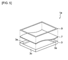
- FIG. 5 is an exploded perspective view illustrating a configuration example of an organic EL display panel 1a of embodiment 2, as assembled.
- the organic EL display panel 1 is disassembled with the display surface 7a facing downward, illustrating a simplified view that focuses on the members related to the embodiment.
- the organic EL display panel 1a of embodiment 2 has substantially the same configuration and behaves in substantially the same manner as embodiment 1.
- the same reference numerals as those in FIGS. 1 to 4 of embodiment 1 denote the same components and behavior, and descriptions thereof will be omitted. The following description will focus on the differences between the embodiments.
- the configuration is as follows. That is, according to embodiment 2, the film moisture-proof substrate 7 is placed in close contact with a reference surface 3a, the fixing frame 9 is pressed against the film moisture-proof substrate 7 from the rear surface thereof to correct the film moisture-proof substrate 7 in accordance with the shape of the reference surface 3a and the fixing frame 9, and the film moisture-proof substrate 7 and the fixing frame 9 are then fixed to the frame body 3 using the moisture-proof adhesive 6.
- the reference surface 3a may be formed on the fixing frame 9 rather than or in addition to the frame body 3.
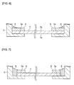
- FIG. 6 is a partial cross-sectional view illustrating an example of the film moisture-proof substrate 7 and the fixing frame 9 fixed to the frame body 3 of FIG. 5 . Since the configuration shown in FIG. 6 is substantially the same as the configuration shown in FIG. 3 of embodiment 1, the following description will focus on the differences therebetween.
- the configuration shown in FIG. 6 in addition to the configuration shown in FIG. 3 , further comprises the fixing frame 9.
- This fixing frame 9 is equivalent to a pressing and fixing frame, and is pressed against a rear surface 7b of the film moisture-proof substrate 7 so that the film moisture-proof substrate 7 comes in close contact with the reference surface 3.
- This fixing frame 9 is disposed so that the film moisture-proof substrate 7 is pressed against the reference surface 3a from one surface (hereinafter represented by the rear surface 7b) of the film moisture-proof substrate 7.
- the film moisture-proof substrate 7 is fixed to the frame body 3 by the moisture-proof adhesive 6 with its rear surface 7b pressed against the reference surface 3a by the fixing frame 9.
- the end surfaces of the film moisture-proof substrate 7 and the fixing frame 9 contact the rear surface of the frame body 3 and are fixed to the frame body 3 from the upper surface of the fixing frame 9 by the moisture-proof adhesive 6, thereby inhibiting penetration of humidity, moisture, and oxygen from the end portions thereof.
- the moisture-proof fixing member includes the pressing and fixing frame 9 (equivalent to the fixing frame) that presses the film moisture-proof substrate 7 from the one surface 7b thereof so that the film moisture-proof substrate 7 comes in close contact with the reference surface 3, using the adhesive 6.
- the film moisture-proof substrate 7 is fixed to the frame body 3 in a state corrected by not only the reference surface 3a but also the pressing and fixing frame 9, thereby correcting the film moisture-proof substrate 7 more closely to a shape that conforms with the reference surface 3a.
- FIG. 7 is a partial cross-sectional view illustrating an alternative embodiment of the film moisture-proof substrate 7 and the fixing frame 9 fixed to the frame body 3 of FIG. 6 .
- the following description of FIG. 7 will focus on the differences between FIG. 6 and embodiment 2.
- the configuration shown in FIG. 7 differs from that shown in FIG. 6 in that each end portion of the film moisture-proof substrate 7 and the fixing frame 9 are not in contact with the rear surface of the fixing body 3, and the moisture-proof adhesive 6 is filled in each end portion of the film moisture-proof substrate 7, the fixing frame 9, and the frame body 3.
- the moisture-proof adhesive 6 is thus filled, the moisture-proof capability increases further than in a case where each end portion is sealed as shown in FIG. 6 , and the moisture-proof adhesive 6 more readily enters each end portion in a sufficient manner, thereby causing the film moisture-proof substrate 7 to be more reliably fixed to the frame body 3 by the moisture-proof adhesive 6.
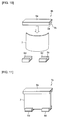
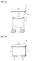
- FIG. 8 and FIG. 9 are each a perspective view illustrating an example of the process, in part, used to assemble an organic EL display panel 1b of embodiment 3. Note that FIG. 8 and FIG. 9 are simplified views that focus on the members related to the embodiment.
- the film moisture-proof substrate 7, distorted as shown in FIG. 8 is sandwiched by a fixing frame 9a from above and a fixing frame 9b from below as shown in FIG. 9 .
- these fixing frames 9a and 9b each form a groove 9c, and each of the grooves 9c of the fixing frames 9a and 9b completely sandwich the upper and lower end portions of the film moisture-proof substrate 7.
- the aforementioned reference surface 3a is formed on the inner peripheral surface of this groove 9c. Note that the reference formed on the inner peripheral surface of the groove 9c may be the aforementioned reference point 3d.
- the aforementioned moisture-proof adhesive 6 is filled in these grooves 9c, and these fixing frames 9a and 9b fix the film moisture-proof substrate 7 with the upper and lower end portions of the film moisture-proof substrate 7 sandwiched therebetween.
- the moisture-proof adhesive 6 is thus filled inside the grooves 9c, the upper and lower end portions of the film moisture-proof substrate 7 are sealed, making it possible to inhibit the penetration of humidity, moisture, and oxygen therefrom.
- the moisture-proof fixing members 9a and 9b each have the groove 9c forming the reference surface 3a, and support the end portions of the rectangular film moisture-proof substrate 7 on mutually opposing sides by the reference surfaces of the grooves 9c.
- the groove-shaped correcting members 9a and 9b are capable of inhibiting penetration of humidity, moisture, and oxygen from the end portions while the grooves 9c support the end surfaces of the film moisture-proof substrate 7.
- FIG. 10 and FIG. 11 are each a perspective view illustrating an example of the process, in part, used to assemble the organic EL display panel 1b of alternative embodiment 1 of embodiment 3. Note that FIG. 10 and FIG. 11 are simplified views that focus on the members related to the embodiment.
- a fixing frame 9d is used in place of the aforementioned fixing frame 9b on the lower side.
- the fixing frame 9a sandwiches the film moisture-proof substrate 7 in substantially the same manner as described above, and a description thereof will be omitted.
- the fixing frame 9d differs from the aforementioned fixing frame 9b by the groove 9c. That is, portions of the end portion of the lower side of the film moisture-proof substrate 7 of the embodiment shown in FIG. 10 are sandwiched as illustrated in FIG. 11 to correct the shape.
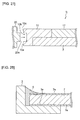
- FIG. 12 is a cross-sectional view illustrating a first cross-sectional configuration example of the fixing frames 9a and 9d shown in FIG. 10 and FIG. 11 .
- the fixing frames 9a and 9d each form the reference surface 3a within the groove 9c.
- the reference surface 3a has the function of correcting the shape of the film moisture-proof substrate 7 while in close contact with the film moisture-proof substrate 7 in substantially the same manner as each of the above embodiments.
- the aforementioned moisture-proof adhesive 6 is filled in the groove 9c, fixing the film moisture-proof substrate 7 disposed within the groove 9c and inhibiting the penetration of humidity, moisture, and oxygen from the end portions thereof.
- FIG. 13 is a cross-sectional view illustrating a second cross-sectional configuration example of the fixing frames 9a and 9d shown in FIG. 10 and FIG. 11 .
- the fixing frame 9a forms the reference points 3d within the groove 9c.
- the reference points 3d have the function of correcting the shape of the film moisture-proof substrate 7 in substantially the same manner as each of the above embodiments.
- the aforementioned moisture-proof adhesive 6 is filled in the groove 9c, fixing the film moisture-proof substrate 7 disposed within the groove 9c and inhibiting the penetration of humidity, moisture, and oxygen from the end portions thereof.
- FIG. 14 is a perspective view illustrating an example of fixing the end portions of the film moisture-proof substrate 7 using fixing frames 9e and 9f. Note that FIG. 14 is a simplified view that focuses on the members related to the embodiment.
- the mutually opposing sides of the four sides of the rectangular film moisture-proof substrate 7 are respectively supported by the fixing frames 9e and 9f.
- the fixing frames 9e and 9f have substantially the same configuration as the aforementioned fixing frames 9a and 9b. According to each of these fixing frames 9e and 9f, the reference surface 3a or the reference point 3d is formed within the groove 9c, and the groove 9c is filled with the moisture-proof adhesive 6 with the film moisture-proof substrate 7 sandwiched therebetween.
- FIG. 15 is a perspective view illustrating an example of the process, in part, used to assemble an organic EL display panel 1c of alternative embodiment 2 of embodiment 3, and FIG. 16 is a cross-sectional view illustrating a configuration example of fixing frames 9g and 9h of FIG. 15 .
- FIG. 15 is a simplified view that focuses on the members related to the embodiment.
- the fixing frames 9e and 9f are each changed to a half-cylindrical shape, as illustrated by the frames 9g and 9h.
- the cross-sectional shapes of the aforementioned fixing frames 9e and 9f are changed into shapes having extended substantially semicircular end portions, forming the fixing frames 9g and 9h as illustrated in FIG. 16 .
- the extended sections form the above-described reference surface 3a, etc.
- the fixing frames 9g and 9h are materials similar to the above fixing frames 9e and 9f, and similarly exhibit a moisture-proof effect.
- the fixing frames 9g and 9h may be designed so that the fixing frame 9g of two sides and the fixing frame 9h of one side are substantially integrated.
- the film moisture-proof substrate 7 may be inserted in the groove 9c of a U-shaped fixing frame 9i as illustrated in FIG. 17 .
- the four sides of the film moisture-proof substrate 7 are then sandwiched by the fixing frames 9h and 9i.
- the reference surface 3a is formed on these fixing frames 9h and 9i.
- the moisture-proof adhesive 6 is filled in the grooves 9c of the fixing frames 9h and 9i with the film moisture-proof substrate 7 in close contact with the reference surface 3a, thereby fixing the film moisture-proof substrate 7 while correcting it according to the reference surface 3a.
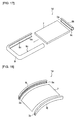
- FIG. 18 and FIG. 19 are each a perspective view illustrating an example of the process, in part, used to assemble an organic EL display panel 1e of embodiment 4. Note that FIG. 18 is a simplified view that focuses on the members related to the embodiment.
- embodiments 1 to 3 each described an illustrative scenario in which the film moisture-proof substrate 7 is corrected to a flat surface
- embodiment 4 describes an illustrative scenario in which the film moisture-proof substrate 7 is corrected to a curved surface of a desired curvature.
- a fixing frame 9j comprises a groove 9c that forms a desired curve, as illustrated in FIG. 18 .
- the cross-sectional shape of this groove 9c is substantially the same as that in the above embodiments 1 to 3, and a description thereof will be omitted.
- the fixing frame 9j has a configuration that makes it possible to sandwich an end portion of the film moisture-proof substrate 7 in the longitudinal direction by the groove 9c. When the film moisture-proof substrate 7 is thus sandwiched by the groove 9c, the fixing frame 9j corrects the film moisture-proof substrate 7 so that it forms a predetermined curved surface along the reference surface 3a of the groove 9c.
- FIG. 19 is a perspective view illustrating an example of the process, in part, used to assemble an organic EL display panel 1f of an alternative embodiment of embodiment 4, and FIG. 20 is a cross-sectional view illustrating a cross-sectional configuration example of a fixing frame 9k of FIG. 19 .
- FIG. 19 and FIG. 20 are simplified views that focus on the members related to the embodiment.
- the sandwiched sections of the film moisture-proof substrate 7 are not limited to the end portions along the longitudinal direction such as illustrated in FIG 18 , allowing use of the end portions along the shorter direction that is substantially perpendicular to the longitudinal direction, as illustrated in FIG. 19 .
- a plurality of the fixing frames 9k that form the groove 9c similar to the fixing frame 9k may sandwich the end portions of two sides along the shorter direction.
- the film moisture-proof substrate 7 is fixed to the fixing frames 9k by the moisture-proof adhesive 6.
- the end portions of the film moisture-proof substrate 7 are sealed by the moisture-proof adhesive 6 to inhibit penetration of humidity, moisture, and oxygen.
- FIG. 21 and FIG. 22 are each a perspective view illustrating an example of the process, in part, used to assemble an organic EL display panel 1g of embodiment 5. Note that FIG. 21 and FIG. 22 are simplified views that focus on the members related to the embodiment.
- embodiment 3 has one film moisture-proof substrate 7 (single substrate)
- embodiment 5 differs from embodiment 3 in that it has two film moisture-proof substrates 7 and 17.
- the film moisture-proof substrate 7 of embodiment 5 has substantially the same configuration as that of the film moisture-proof substrate 7 of the above embodiment 3.
- the film moisture-proof substrates 7 and 17 may be pasted together, or may be a plurality of substrates that are not pasted together.
- the film moisture-proof substrate 17 is a substrate that is equivalent to the other film moisture-proof substrate, having, for example, a moisture-proof action, and comprises a function of protecting the film moisture-proof substrate 7 from humidity, moisture, and oxygen.
- This film moisture-proof substrate 17 thus exhibits moisture-proof characteristics, but does not have the aforementioned thin-film organic electroluminescent elements, unlike the film moisture-proof substrate 7.
- the sealing plate of the fixing and sealing process corresponds to 17.
- the film moisture-proof substrate 17 is provided along the front surface of the film moisture-proof substrate 7. With the film moisture-proof substrate 7 and the film moisture-proof substrate 17 thus superimposed, the upper and lower end portions thereof are supported by the fixing frames 9a and 9b, respectively. At this time, the upper and lower end portions are corrected by the reference surface 3a provided to both the fixing frames 9a and 9b and, as a result, the film moisture-proof substrate 7 and the film moisture-proof substrate 17 are corrected to a desired shape.
- Examples of the material used for the moisture-proof film of the film moisture-proof substrate 7 and the film moisture-proof substrate 17 mainly include inorganic silicon films, such as SiON, SiO 2 , SiN, and SiOC.
- the moisture-proof film formation method used may be a vacuum thin film coating method, such as spattering or CVD, for example.
- a substrate having a moisture-proof function is formed by forming a moisture-proof film on a film substrate. According to such a configuration, it is possible to inhibit the penetration of moisture and oxygen from both the front and rear surfaces of the formed substrate. Note that the aforementioned surface 3a contacts this moisture-proof film.
- the film moisture-proof substrate 7 and the film moisture-proof substrate 17 may be bonded together using an adhesive, for example.
- the adhesive used include an acrylic or epoxy that is based on thermal or UV (ultraviolet light) curing, similar to that used when adhering the fixing plates 9a and 9b, for example. While this embodiment describes an illustrative scenario in which a plurality of substrates (the film moisture-proof substrate 7 and the film moisture-proof substrate 17) is employed, a process technique referred to as solid sealing may be mainly used to seal the substrates and sealing plates in organic EL display panel applications.
- the organic EL display panel 1g of the above embodiment in addition to the above configuration, further comprises another film moisture-proof substrate 17 provided along the front surface of the film moisture-proof substrate 7, wherein the moisture-proof fixing members 9a and 9b are fixed with the other film moisture-proof substrate 17 superimposed on the film moisture-proof substrate 7 using the adhesive 6.
- the film moisture-proof substrate 7 is provided on the front surface of the film moisture-proof substrate 7, the film moisture-proof substrate 7 is capable of inhibiting the penetration of humidity, moisture, and oxygen from the end portions as well as the front surface of the film moisture-proof substrate 7.
- the film moisture-proof substrate 7 is corrected in accordance with the reference surface 3a along with the other film moisture-proof substrate 17.
- FIG. 23 and FIG. 24 are each a perspective view illustrating an example of the process, in part, used to assemble an organic EL display panel 1h of an alternative embodiment of embodiment 5. Note that FIG. 23 and FIG. 24 are simplified views that focus on the members related to the embodiment.
- the fixing frames 9d are used in place of the aforementioned fixing frame 9b on the lower side.
- the fixing frame 9a sandwiches the film moisture-proof substrate 7 in substantially the same manner as described above, and a description thereof will be omitted.
- This fixing frames 9d differ from the aforementioned fixing frames 9b by the groove 9c. That is, portions of the lower end portion of the film moisture-proof substrate 7 of the embodiment shown in FIG. 23 are sandwiched as illustrated in FIG. 24 .
- FIG. 25 is a cross-sectional view illustrating a cross-sectional configuration example of the fixing frames 9a and 9d shown in FIG. 23 and FIG. 24 .
- the fixing frames 9a and 9d each form the reference surface 3a within the groove 9c.
- the reference surface 3a has the function of correcting the shape of the film moisture-proof substrate 7 in substantially the same manner as each of the above embodiments.
- the aforementioned moisture-proof adhesive 6 is filled in the groove 9c, fixing the film moisture-proof substrate 7 disposed within the groove 9c and inhibiting the penetration of humidity, moisture, and oxygen from the end portions thereof.
- the film moisture-proof substrate 7 is fixed to the frame body 3 along with the film moisture-proof substrate 17 while in close contact with the reference surface 3a, using the moisture-proof adhesive 6. This makes it possible to prevent the film moisture-proof substrate 17 from separating from the film moisture-proof substrate 7.
- FIG. 26 is a cross-sectional view illustrating a configuration example of a portion of an organic EL display panel 1i of alternative embodiment 1 of each of the above embodiments. Note that in alternative embodiment 1 a description will be omitted for those components that are substantially the same as those of each of the above-described embodiments, and the focus will be placed on the differences from each of the above embodiments.
- the film moisture-proof 7 is fixed to a fixing frame 10 (equivalent to a moisture-proof fixing member) while superimposed on the film moisture-proof substrate 17, similar to the above embodiment 5.
- the combined thickness of the film moisture-proof substrate 7 and the film moisture-proof substrate 17 is substantially the same as the thickness of the fixing frame 10.
- a slight difference in surface area exists between the film moisture-proof substrate 7 and the film-moisture proof substrate 17.
- the section formed by this surface area difference is in close contact with the fixing frame 10, which has the reference surface 3a that is substantially the same as in each of the above embodiments.
- the surface area of the film moisture-proof substrate 17 is smaller than the surface area of the film moisture-proof substrate 7, and the surface of a portion of the film moisture-proof substrate 7 is in close contact with the reference surface 3a of the fixing frame 10.
- the fixing frame 10 has a moisture-proof function that inhibits humidity and moisture and an oxygen permeation control function.
- the reference surface 3a similar to each of the above embodiments, has the function of correcting the film moisture-proof substrate 7 so that it forms a desired shape.
- this fixing frame 10 is mainly disposed on the side of the film moisture-proof substrate 7 and the film moisture-proof substrate 17 to cover the end potions thereof, thereby inhibiting the penetration of humidity, moisture, and oxygen from the end portions.
- the moisture-proof fixing member comprises the reference surface 3a that is in close contact the section of the bonded film moisture-proof substrate 7 and the film moisture-proof substrate 17 where there is a difference in surface area, and the fixing member body 10 (equivalent to the fixing frame) that fixes the film moisture-proof substrate 7 and the other film moisture-proof substrate 17 in a superimposed state.
- the reference surface 3a of the fixing member body 10 is capable of correcting the film moisture-proof substrate 7 and the other film moisture-proof substrate 17 to a desired shape, and the fixing member body 10 is capable of exhibiting a moisture-proof effect that inhibits the penetration of humidity and moisture from each end portion of the film moisture-proof substrate 7 and the other film moisture-proof substrate 17 as well as decreasing the size in the thickness direction.
- the organic EL display panel 1i of the above embodiment comprises a configuration wherein, in addition to the above configuration, the thickness of the fixing member body 10 is substantially equal to the combined thickness of the superimposed film moisture-proof substrate 7 and the other film moisture-proof substrate 17.
- the thickness of the fixing member body 10 is equal to the thickness of the film moisture-proof substrate 7 and the other film moisture-proof substrate 17, thereby making it possible to flatten the area from the fixing member body 10 to the front surface of the film moisture-proof substrate 7 or the other film moisture-proof substrate 17. This makes it possible to achieve the thinness demanded in a film EL.
- FIG. 27 is a cross-sectional view illustrating a configuration example of a portion of an organic EL display panel 1j of alternative embodiment 2, which is a further modification of the alternative embodiment 1.
- the configuration is substantially the same as that of alternative embodiment 1, but the shape of the fixing member body 10 differs as follows.
- a second joining portion 10b of a groove shape is formed on a side surface 10c of the fixing member body 10 of the above alternative embodiment 1.
- a first joining portion 20a of a convex shape is formed on a display device body 20 that emits light from the film moisture-proof substrate 7 to display a desired image.
- This first joining portion 20a is designed to mate with the second joining portion 10b.
- the moisture permeability of the fixing member body 10 is, for example, greater than or equal to 0.01 [g/m 2 per day] and less than or equal to 100 [g/m 2 per day].
- the material used for the fixing member body 10 is, for example, a moisture-proof insulating material made by Hitachi Chemical to protect the end portions of the film moisture-proof substrate 7 and the like. Note that this moisture-proof insulating material is often employed as a material for a flat panel display, for example.
- the second joining portion 10b is bonded to the first joining portion 20a using the adhesive 6 that is of an ultraviolet curing or thermal curing type, for example.
- the second joining portion 10b that mates with the first joining portion 20a of the display device body 20 that emits light from the film moisture-proof substrate 7 to display a desired image is formed on the fixing member 10.
- the first joining portion 20a and the second joining portion 10b join together and correct the film moisture-proof substrate 7 in such a manner that the reference surface 3a minimizes the deformation thereof in the event the organic EL display panel 1j is subjected to impact when mounted on the display device body 20 causing deformation of the film moisture-proof substrate 7.
- the organic EL display panel 1j of the above embodiment comprises a configuration wherein, in addition to the above configuration, the coefficients of linear expansion of the film moisture-proof substrate 7, the other film moisture-proof substrate 17, and the fixing member body 10 are substantially equal.
- the fixing member body 10 shapes the film moisture-proof substrate 7 and the other film moisture-proof substrate 17 in substantially the same manner, even if the film moisture-proof substrate 7 and the other film moisture-proof substrate 17 have deformed over time, thereby making the film moisture-proof substrate 7, the other film moisture-proof substrate 17, and the fixing member body 10 expand substantially in the same manner if moisture is absorbed.
- the organic EL display panel 1j is capable of minimizing the effect caused by a difference in expansion due to deformation over time of the film moisture-proof substrate 7, the other film moisture-proof substrate 17, and the fixing member body 10.
- the moisture permeability of the fixing member body 10 is greater than or equal to 0.01 [g/m 2 per day] and less than or equal to 100 [g/m 2 per day], for example.
- the organic EL display panel 1 to 1h of each of the above embodiments may further comprise the fixing member body 10 that fixes a side of the film moisture-proof substrate 7. That is, the above fixing member body 10 may fix the film moisture-proof substrate 7 that is not provided with such the film moisture-proof substrate 17, from the side.
- the second joining portion 10b that mates with the first joining portion 20a of the display device body 20 that emits light from the film moisture-proof substrate 7 to display a desired image is formed on the fixing member body 10.
- the first joining portion 20a and the second joining portion 10b join together and correct the film moisture-proof substrate 7 in such a manner that the reference surface 3a minimizes the deformation thereof in the event the organic EL display panels 1 to 1h are subjected to impact when mounted on the display device body 20 causing deformation of the film moisture-proof substrate 7.
- the organic EL display panels 1 to 1h of each of the above embodiments comprises a configuration wherein, in addition to the above configuration, the linear coefficients of expansion of the film moisture-proof substrate 7 and the fixing member body 10 are substantially equal.
- the fixing member body 10 changes shape in substantially the same manner as the film moisture-proof substrate 7, even if the film moisture-proof substrate 7 has deformed over time, causing the film moisture-proof substrate 7 and the fixing member body 10 to expand substantially in the same manner if moisture is absorbed.
- the organic EL display panels 1 to 1h are each capable of minimizing the effect caused by the difference in expansion due to deformation over time of the film moisture-proof substrate 7 and the fixing member body 10.
- the moisture permeability of the fixing member body 10 is greater than or equal to 0.01 [g/m 2 per day] and less than or equal to 100 [g/m 2 per day], for example.
- FIG. 28 is a partial cross-sectional view illustrating an alternative embodiment of the film moisture-proof substrate 7 of FIG. 3 .
- the components are substantially the same as those of FIG. 3 of embodiment 1. Descriptions of identical components will therefore be omitted, and the focus will be placed on the differences between the embodiments.
- a moisture-proof film 7e is provided as an example of the other film moisture-proof substrate.
- This moisture-proof film 7e is an inorganic film, for example, and has a moisture-proof function similar to that of the aforementioned film moisture-proof substrate 17.
- the moisture-proof films 7e of both surfaces are formed on both surfaces of the film moisture-proof substrate 7.
- the film moisture-proof substrate 7 is fixed to the frame body 3 using the moisture-proof adhesive 6, with the moisture-proof film 7e in contact with the reference surface 3a. With this arrangement, it is possible to prevent separation of the moisture-proof film 7e.
- the other film moisture-proof substrate may serve as the moisture-proof film 7e formed on the front and rear surfaces of the film moisture-proof substrate 7.
- the film moisture-proof substrate 7 is capable of exhibiting a moisture-proof effect that inhibits penetration of humidity and moisture from the end portions thereof, as well as exhibiting a moisture-proof effect that inhibits penetration of humidity and moisture from the front and rear surfaces thereof.
- Such general applicable film devices include, for example, organic electroluminescent displays, organic transistors, organic solar cells, semiconductor lasers, and CNT-FET transistors.
Landscapes
- Physics & Mathematics (AREA)
- Optics & Photonics (AREA)
- Electroluminescent Light Sources (AREA)
- Devices For Indicating Variable Information By Combining Individual Elements (AREA)
- Illuminated Signs And Luminous Advertising (AREA)
Applications Claiming Priority (1)
| Application Number | Priority Date | Filing Date | Title |
|---|---|---|---|
| PCT/JP2007/065733 WO2009022380A1 (fr) | 2007-08-10 | 2007-08-10 | Panneau d'affichage à électroluminescence organique et son procédé de fabrication |
Publications (3)
| Publication Number | Publication Date |
|---|---|
| EP2180761A1 true EP2180761A1 (fr) | 2010-04-28 |
| EP2180761A4 EP2180761A4 (fr) | 2011-01-05 |
| EP2180761B1 EP2180761B1 (fr) | 2012-02-01 |
Family
ID=40350444
Family Applications (1)
| Application Number | Title | Priority Date | Filing Date |
|---|---|---|---|
| EP07792378A Not-in-force EP2180761B1 (fr) | 2007-08-10 | 2007-08-10 | Panneau d'affichage à électroluminescence organique et son procédé de fabrication |
Country Status (6)
| Country | Link |
|---|---|
| US (1) | US20110095677A1 (fr) |
| EP (1) | EP2180761B1 (fr) |
| JP (1) | JP5021034B2 (fr) |
| AT (1) | ATE544317T1 (fr) |
| TW (1) | TW200917884A (fr) |
| WO (1) | WO2009022380A1 (fr) |
Families Citing this family (6)
| Publication number | Priority date | Publication date | Assignee | Title |
|---|---|---|---|---|
| DK2596527T3 (da) * | 2010-07-22 | 2019-08-12 | Ferro Corp | Metode til hermetisk forsejling af et aktivt lag og tilsvarende fotovoltaisk indretning |
| JP6323806B2 (ja) * | 2014-06-30 | 2018-05-16 | パナソニックIpマネジメント株式会社 | 発光デバイス及び移動体 |
| JP6591150B2 (ja) * | 2014-09-25 | 2019-10-16 | パイオニア株式会社 | 発光装置 |
| JP2018174160A (ja) * | 2018-08-03 | 2018-11-08 | 株式会社小糸製作所 | 灯具 |
| CN112639554B (zh) * | 2018-09-04 | 2022-10-28 | 富士胶片株式会社 | 层叠体、有机电致发光装置、液晶显示装置 |
| JP2019212641A (ja) * | 2019-09-18 | 2019-12-12 | パイオニア株式会社 | 発光装置 |
Family Cites Families (9)
| Publication number | Priority date | Publication date | Assignee | Title |
|---|---|---|---|---|
| JP2000105557A (ja) * | 1998-09-30 | 2000-04-11 | Mitsubishi Materials Corp | El発光シートを用いる薄型曲面発光パネル及びその製造方法 |
| US6724150B2 (en) * | 2001-02-01 | 2004-04-20 | Semiconductor Energy Laboratory Co., Ltd. | Display device and manufacturing method thereof |
| JP3838964B2 (ja) | 2002-03-13 | 2006-10-25 | 株式会社リコー | 機能性素子基板の製造装置 |
| JP4010845B2 (ja) * | 2002-03-28 | 2007-11-21 | 富士フイルム株式会社 | 発光素子 |
| JP4273808B2 (ja) * | 2003-03-31 | 2009-06-03 | セイコーエプソン株式会社 | 電気光学装置、及び電気光学装置の製造方法、並びに電子機器 |
| JP2005222807A (ja) * | 2004-02-05 | 2005-08-18 | Seiko Epson Corp | 封止構造体、電子機器及び画像形成装置 |
| JP4440003B2 (ja) * | 2004-06-09 | 2010-03-24 | 富士フイルム株式会社 | デジタルカメラ |
| KR100719540B1 (ko) * | 2004-11-18 | 2007-05-17 | 삼성에스디아이 주식회사 | 평판표시패널용 지지장치 및 이를 구비한 평판표시장치 |
| JP4663554B2 (ja) * | 2006-03-09 | 2011-04-06 | 株式会社半導体エネルギー研究所 | 表示装置の作製方法 |
-
2007
- 2007-08-10 AT AT07792378T patent/ATE544317T1/de active
- 2007-08-10 US US12/673,215 patent/US20110095677A1/en not_active Abandoned
- 2007-08-10 WO PCT/JP2007/065733 patent/WO2009022380A1/fr not_active Ceased
- 2007-08-10 EP EP07792378A patent/EP2180761B1/fr not_active Not-in-force
- 2007-08-10 JP JP2009527971A patent/JP5021034B2/ja not_active Expired - Fee Related
-
2008
- 2008-08-08 TW TW097130236A patent/TW200917884A/zh unknown
Also Published As
| Publication number | Publication date |
|---|---|
| US20110095677A1 (en) | 2011-04-28 |
| TW200917884A (en) | 2009-04-16 |
| EP2180761A4 (fr) | 2011-01-05 |
| ATE544317T1 (de) | 2012-02-15 |
| EP2180761B1 (fr) | 2012-02-01 |
| WO2009022380A1 (fr) | 2009-02-19 |
| JPWO2009022380A1 (ja) | 2010-11-11 |
| JP5021034B2 (ja) | 2012-09-05 |
Similar Documents
| Publication | Publication Date | Title |
|---|---|---|
| JP6694928B2 (ja) | フレキシブルディスプレイ装置 | |
| EP2180761B1 (fr) | Panneau d'affichage à électroluminescence organique et son procédé de fabrication | |
| US7920224B2 (en) | Display device | |
| US9104049B2 (en) | Display device with a base material made of plastic | |
| JP2004303733A (ja) | 構成素子、とりわけ有機発光ダイオードを備える表示装置 | |
| CN104685554A (zh) | 显示装置 | |
| US9565779B2 (en) | Display unit, electronic device and assembling method for electronic device | |
| KR20110004398A (ko) | 시일된 유리 조립체용 베젤 패키징 및 유리 조립체 | |
| CN101326109A (zh) | 玻璃料密封的oled器件的企口沟缘封装 | |
| US20120293960A1 (en) | Display device | |
| US10459266B2 (en) | Display module, display apparatus having the same, and fabricating method thereof | |
| US8519531B2 (en) | Electrical and/or electronic device with elastic contact element | |
| US8462290B2 (en) | Flat screen device with transparent protection housing | |
| US20100171684A1 (en) | Plasma display device | |
| WO2011152271A1 (fr) | Module de cellules solaires | |
| US8711308B2 (en) | Flat panel display device and method of fabricating the same | |
| US20100157514A1 (en) | Display apparatus and display module including the same | |
| US9978984B2 (en) | Method for fabricating packing assembly for display panel including expanding stacked packing assembly segments | |
| CN110782780B (zh) | 胶带结构及使用其的显示面板和显示装置 | |
| US20110128684A1 (en) | Display module | |
| CN205881372U (zh) | 显示模组、具有显示模组的显示设备 | |
| JP2009230129A (ja) | 表示パネル及び表示パネルの製造方法 | |
| CN106097911A (zh) | 显示模组、具有显示模组的显示设备、及其制备方法 | |
| US20240170781A1 (en) | Battery module | |
| JP2011198886A (ja) | 太陽電池モジュール及び太陽電池モジュールの製造方法 |
Legal Events
| Date | Code | Title | Description |
|---|---|---|---|
| PUAI | Public reference made under article 153(3) epc to a published international application that has entered the european phase |
Free format text: ORIGINAL CODE: 0009012 |
|
| 17P | Request for examination filed |
Effective date: 20100225 |
|
| AK | Designated contracting states |
Kind code of ref document: A1 Designated state(s): AT BE BG CH CY CZ DE DK EE ES FI FR GB GR HU IE IS IT LI LT LU LV MC MT NL PL PT RO SE SI SK TR |
|
| AX | Request for extension of the european patent |
Extension state: AL BA HR MK RS |
|
| DAX | Request for extension of the european patent (deleted) | ||
| A4 | Supplementary search report drawn up and despatched |
Effective date: 20101202 |
|
| RAP1 | Party data changed (applicant data changed or rights of an application transferred) |
Owner name: PIONEER CORPORATION |
|
| GRAP | Despatch of communication of intention to grant a patent |
Free format text: ORIGINAL CODE: EPIDOSNIGR1 |
|
| RIC1 | Information provided on ipc code assigned before grant |
Ipc: H05B 33/10 20060101ALI20110725BHEP Ipc: H05B 33/02 20060101ALI20110725BHEP Ipc: H01L 27/32 20060101ALI20110725BHEP Ipc: H01L 51/50 20060101ALI20110725BHEP Ipc: G09F 9/30 20060101ALI20110725BHEP Ipc: H05B 33/04 20060101AFI20110725BHEP |
|
| GRAS | Grant fee paid |
Free format text: ORIGINAL CODE: EPIDOSNIGR3 |
|
| GRAA | (expected) grant |
Free format text: ORIGINAL CODE: 0009210 |
|
| AK | Designated contracting states |
Kind code of ref document: B1 Designated state(s): AT BE BG CH CY CZ DE DK EE ES FI FR GB GR HU IE IS IT LI LT LU LV MC MT NL PL PT RO SE SI SK TR |
|
| REG | Reference to a national code |
Ref country code: GB Ref legal event code: FG4D |
|
| REG | Reference to a national code |
Ref country code: AT Ref legal event code: REF Ref document number: 544317 Country of ref document: AT Kind code of ref document: T Effective date: 20120215 Ref country code: CH Ref legal event code: EP Ref country code: GB Ref legal event code: 746 Effective date: 20120125 |
|
| REG | Reference to a national code |
Ref country code: DE Ref legal event code: R096 Ref document number: 602007020437 Country of ref document: DE Effective date: 20120329 |
|
| REG | Reference to a national code |
Ref country code: NL Ref legal event code: VDEP Effective date: 20120201 |
|
| LTIE | Lt: invalidation of european patent or patent extension |
Effective date: 20120201 |
|
| PG25 | Lapsed in a contracting state [announced via postgrant information from national office to epo] |
Ref country code: IS Free format text: LAPSE BECAUSE OF FAILURE TO SUBMIT A TRANSLATION OF THE DESCRIPTION OR TO PAY THE FEE WITHIN THE PRESCRIBED TIME-LIMIT Effective date: 20120601 Ref country code: NL Free format text: LAPSE BECAUSE OF FAILURE TO SUBMIT A TRANSLATION OF THE DESCRIPTION OR TO PAY THE FEE WITHIN THE PRESCRIBED TIME-LIMIT Effective date: 20120201 Ref country code: LT Free format text: LAPSE BECAUSE OF FAILURE TO SUBMIT A TRANSLATION OF THE DESCRIPTION OR TO PAY THE FEE WITHIN THE PRESCRIBED TIME-LIMIT Effective date: 20120201 |
|
| PG25 | Lapsed in a contracting state [announced via postgrant information from national office to epo] |
Ref country code: LV Free format text: LAPSE BECAUSE OF FAILURE TO SUBMIT A TRANSLATION OF THE DESCRIPTION OR TO PAY THE FEE WITHIN THE PRESCRIBED TIME-LIMIT Effective date: 20120201 Ref country code: PL Free format text: LAPSE BECAUSE OF FAILURE TO SUBMIT A TRANSLATION OF THE DESCRIPTION OR TO PAY THE FEE WITHIN THE PRESCRIBED TIME-LIMIT Effective date: 20120201 Ref country code: BE Free format text: LAPSE BECAUSE OF FAILURE TO SUBMIT A TRANSLATION OF THE DESCRIPTION OR TO PAY THE FEE WITHIN THE PRESCRIBED TIME-LIMIT Effective date: 20120201 Ref country code: FI Free format text: LAPSE BECAUSE OF FAILURE TO SUBMIT A TRANSLATION OF THE DESCRIPTION OR TO PAY THE FEE WITHIN THE PRESCRIBED TIME-LIMIT Effective date: 20120201 Ref country code: GR Free format text: LAPSE BECAUSE OF FAILURE TO SUBMIT A TRANSLATION OF THE DESCRIPTION OR TO PAY THE FEE WITHIN THE PRESCRIBED TIME-LIMIT Effective date: 20120502 Ref country code: PT Free format text: LAPSE BECAUSE OF FAILURE TO SUBMIT A TRANSLATION OF THE DESCRIPTION OR TO PAY THE FEE WITHIN THE PRESCRIBED TIME-LIMIT Effective date: 20120601 |
|
| REG | Reference to a national code |
Ref country code: AT Ref legal event code: MK05 Ref document number: 544317 Country of ref document: AT Kind code of ref document: T Effective date: 20120201 |
|
| PG25 | Lapsed in a contracting state [announced via postgrant information from national office to epo] |
Ref country code: CY Free format text: LAPSE BECAUSE OF FAILURE TO SUBMIT A TRANSLATION OF THE DESCRIPTION OR TO PAY THE FEE WITHIN THE PRESCRIBED TIME-LIMIT Effective date: 20120201 |
|
| PG25 | Lapsed in a contracting state [announced via postgrant information from national office to epo] |
Ref country code: SE Free format text: LAPSE BECAUSE OF FAILURE TO SUBMIT A TRANSLATION OF THE DESCRIPTION OR TO PAY THE FEE WITHIN THE PRESCRIBED TIME-LIMIT Effective date: 20120201 Ref country code: SI Free format text: LAPSE BECAUSE OF FAILURE TO SUBMIT A TRANSLATION OF THE DESCRIPTION OR TO PAY THE FEE WITHIN THE PRESCRIBED TIME-LIMIT Effective date: 20120201 Ref country code: CZ Free format text: LAPSE BECAUSE OF FAILURE TO SUBMIT A TRANSLATION OF THE DESCRIPTION OR TO PAY THE FEE WITHIN THE PRESCRIBED TIME-LIMIT Effective date: 20120201 Ref country code: EE Free format text: LAPSE BECAUSE OF FAILURE TO SUBMIT A TRANSLATION OF THE DESCRIPTION OR TO PAY THE FEE WITHIN THE PRESCRIBED TIME-LIMIT Effective date: 20120201 Ref country code: DK Free format text: LAPSE BECAUSE OF FAILURE TO SUBMIT A TRANSLATION OF THE DESCRIPTION OR TO PAY THE FEE WITHIN THE PRESCRIBED TIME-LIMIT Effective date: 20120201 Ref country code: RO Free format text: LAPSE BECAUSE OF FAILURE TO SUBMIT A TRANSLATION OF THE DESCRIPTION OR TO PAY THE FEE WITHIN THE PRESCRIBED TIME-LIMIT Effective date: 20120201 |
|
| PGFP | Annual fee paid to national office [announced via postgrant information from national office to epo] |
Ref country code: GB Payment date: 20120808 Year of fee payment: 6 |
|
| PG25 | Lapsed in a contracting state [announced via postgrant information from national office to epo] |
Ref country code: SK Free format text: LAPSE BECAUSE OF FAILURE TO SUBMIT A TRANSLATION OF THE DESCRIPTION OR TO PAY THE FEE WITHIN THE PRESCRIBED TIME-LIMIT Effective date: 20120201 Ref country code: IT Free format text: LAPSE BECAUSE OF FAILURE TO SUBMIT A TRANSLATION OF THE DESCRIPTION OR TO PAY THE FEE WITHIN THE PRESCRIBED TIME-LIMIT Effective date: 20120201 |
|
| PLBE | No opposition filed within time limit |
Free format text: ORIGINAL CODE: 0009261 |
|
| STAA | Information on the status of an ep patent application or granted ep patent |
Free format text: STATUS: NO OPPOSITION FILED WITHIN TIME LIMIT |
|
| PGFP | Annual fee paid to national office [announced via postgrant information from national office to epo] |
Ref country code: FR Payment date: 20120823 Year of fee payment: 6 |
|
| 26N | No opposition filed |
Effective date: 20121105 |
|
| PG25 | Lapsed in a contracting state [announced via postgrant information from national office to epo] |
Ref country code: AT Free format text: LAPSE BECAUSE OF FAILURE TO SUBMIT A TRANSLATION OF THE DESCRIPTION OR TO PAY THE FEE WITHIN THE PRESCRIBED TIME-LIMIT Effective date: 20120201 |
|
| REG | Reference to a national code |
Ref country code: DE Ref legal event code: R097 Ref document number: 602007020437 Country of ref document: DE Effective date: 20121105 |
|
| REG | Reference to a national code |
Ref country code: CH Ref legal event code: PL |
|
| PG25 | Lapsed in a contracting state [announced via postgrant information from national office to epo] |
Ref country code: MC Free format text: LAPSE BECAUSE OF NON-PAYMENT OF DUE FEES Effective date: 20120831 |
|
| PG25 | Lapsed in a contracting state [announced via postgrant information from national office to epo] |
Ref country code: ES Free format text: LAPSE BECAUSE OF FAILURE TO SUBMIT A TRANSLATION OF THE DESCRIPTION OR TO PAY THE FEE WITHIN THE PRESCRIBED TIME-LIMIT Effective date: 20120512 Ref country code: LI Free format text: LAPSE BECAUSE OF NON-PAYMENT OF DUE FEES Effective date: 20120831 Ref country code: CH Free format text: LAPSE BECAUSE OF NON-PAYMENT OF DUE FEES Effective date: 20120831 |
|
| REG | Reference to a national code |
Ref country code: IE Ref legal event code: MM4A |
|
| PG25 | Lapsed in a contracting state [announced via postgrant information from national office to epo] |
Ref country code: BG Free format text: LAPSE BECAUSE OF FAILURE TO SUBMIT A TRANSLATION OF THE DESCRIPTION OR TO PAY THE FEE WITHIN THE PRESCRIBED TIME-LIMIT Effective date: 20120501 Ref country code: DE Free format text: LAPSE BECAUSE OF NON-PAYMENT OF DUE FEES Effective date: 20130301 Ref country code: IE Free format text: LAPSE BECAUSE OF NON-PAYMENT OF DUE FEES Effective date: 20120810 |
|
| REG | Reference to a national code |
Ref country code: DE Ref legal event code: R119 Ref document number: 602007020437 Country of ref document: DE Effective date: 20130301 |
|
| PG25 | Lapsed in a contracting state [announced via postgrant information from national office to epo] |
Ref country code: MT Free format text: LAPSE BECAUSE OF FAILURE TO SUBMIT A TRANSLATION OF THE DESCRIPTION OR TO PAY THE FEE WITHIN THE PRESCRIBED TIME-LIMIT Effective date: 20120201 |
|
| GBPC | Gb: european patent ceased through non-payment of renewal fee |
Effective date: 20130810 |
|
| PG25 | Lapsed in a contracting state [announced via postgrant information from national office to epo] |
Ref country code: TR Free format text: LAPSE BECAUSE OF FAILURE TO SUBMIT A TRANSLATION OF THE DESCRIPTION OR TO PAY THE FEE WITHIN THE PRESCRIBED TIME-LIMIT Effective date: 20120201 |
|
| REG | Reference to a national code |
Ref country code: FR Ref legal event code: ST Effective date: 20140430 |
|
| PG25 | Lapsed in a contracting state [announced via postgrant information from national office to epo] |
Ref country code: LU Free format text: LAPSE BECAUSE OF NON-PAYMENT OF DUE FEES Effective date: 20120810 |
|
| PG25 | Lapsed in a contracting state [announced via postgrant information from national office to epo] |
Ref country code: HU Free format text: LAPSE BECAUSE OF FAILURE TO SUBMIT A TRANSLATION OF THE DESCRIPTION OR TO PAY THE FEE WITHIN THE PRESCRIBED TIME-LIMIT Effective date: 20070810 Ref country code: GB Free format text: LAPSE BECAUSE OF NON-PAYMENT OF DUE FEES Effective date: 20130810 |
|
| PG25 | Lapsed in a contracting state [announced via postgrant information from national office to epo] |
Ref country code: FR Free format text: LAPSE BECAUSE OF NON-PAYMENT OF DUE FEES Effective date: 20130902 |