EP2180764A2 - Systeme und Verfahren für sicherheitsgesteuerte LED-Leuchte - Google Patents
Systeme und Verfahren für sicherheitsgesteuerte LED-Leuchte Download PDFInfo
- Publication number
- EP2180764A2 EP2180764A2 EP09173555A EP09173555A EP2180764A2 EP 2180764 A2 EP2180764 A2 EP 2180764A2 EP 09173555 A EP09173555 A EP 09173555A EP 09173555 A EP09173555 A EP 09173555A EP 2180764 A2 EP2180764 A2 EP 2180764A2
- Authority
- EP
- European Patent Office
- Prior art keywords
- leds
- power
- led
- authorization signal
- secure
- Prior art date
- Legal status (The legal status is an assumption and is not a legal conclusion. Google has not performed a legal analysis and makes no representation as to the accuracy of the status listed.)
- Granted
Links
Images


Classifications
-
- H—ELECTRICITY
- H05—ELECTRIC TECHNIQUES NOT OTHERWISE PROVIDED FOR
- H05B—ELECTRIC HEATING; ELECTRIC LIGHT SOURCES NOT OTHERWISE PROVIDED FOR; CIRCUIT ARRANGEMENTS FOR ELECTRIC LIGHT SOURCES, IN GENERAL
- H05B45/00—Circuit arrangements for operating light-emitting diodes [LED]
- H05B45/50—Circuit arrangements for operating light-emitting diodes [LED] responsive to malfunctions or undesirable behaviour of LEDs; responsive to LED life; Protective circuits
-
- H—ELECTRICITY
- H05—ELECTRIC TECHNIQUES NOT OTHERWISE PROVIDED FOR
- H05B—ELECTRIC HEATING; ELECTRIC LIGHT SOURCES NOT OTHERWISE PROVIDED FOR; CIRCUIT ARRANGEMENTS FOR ELECTRIC LIGHT SOURCES, IN GENERAL
- H05B45/00—Circuit arrangements for operating light-emitting diodes [LED]
- H05B45/30—Driver circuits
Definitions
- LED fixtures are configured to secure a plurality of light emitting LEDs.
- the LEDs may emit non-visible electromagnetic energy, such as infrared light.
- Lens and reflectors in the LED fixture may be used to focus and/or direct the light emitted by the LEDs.
- a controller controls operation of the LEDs.
- the LED controller may be controlled in a manner where the LEDs are operated in an "on” state, wherein light is emitted from the LEDs, or to an "off” state, wherein no light is emitted, by controlling the duty cycle of the power provided to the LEDs.
- the color and/or intensity of the emitted light is controllable.
- the LED fixture may be designed in a modular fashion such that the entire LED fixture may be readily installed into and/or removed from a fixture mounting.
- the fixture mounting may be attached to, or incorporated within, an application device.
- the application device include aircraft, automobiles, and signs.
- the LED fixture may be readily removed and replaced with a fully operational LED fixture. Replacing the entire LED fixture, rather than disassembling the LED fixture to replace individual LEDs, may save time and expense.
- Coupling of the electrical connections of the LED light fixture to corresponding connections in the fixture mounting may be implemented with slidably engaging mating electrical connectors. Clamps, screws or other fasteners are typically used to affix the LED light fixture to its fixture mounting. Further, the shape of the LED fixture may match the shape of the fixture mounting so as to prevent the use of incompatible LED fixtures.
- the particular application may require precise control of the light emitted from the LED fixture.
- the direction, color, and/or intensity of the emitted light must satisfy predefined safety standards to ensure aircraft safety.
- the LED lighting system is not secure against the use of noncompliant LED fixtures, it may be possible for a noncompliant LED fixture to be connected to the fixture mounting whereby an incorrect direction, color, and/or intensity of the emitted light may fail to satisfy the predefined safety standards. Accordingly, it is desirable to provide a secure LED lighting system that is operable only with a compliant LED fixture, and that is inoperable with a noncompliant LED fixture.
- An exemplary embodiment provides power to the plurality of LEDs and senses the power provided to the LEDs. In response to sensing the power, an authorization signal is communicated from a security sensor residing in the secure LED fixture. Power to the plurality of LEDs is maintained only in response to the communicated authorization signal.
- an exemplary embodiment has a secure LED fixture with a plurality of LEDs, a secure LED fixture mounting configured to physically couple to the secure LED fixture, a LED driver and controller configured to electrically couple the plurality of LEDs to a power source, and a security sensor residing in the secure LED fixture.
- the security sensor senses power initially provided to the plurality of LEDs and communicates an authorization signal in response to sensing the power. Power is maintained to the plurality of LEDs only in response to communication of the authorization signal.
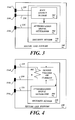
- FIGURE 1 is a block diagram of an embodiment of a secured light emitting diode (LED) system
- FIGURE 2 is a block diagram of an embodiment of the secure LED system that interrupts power delivery to a noncompliant LED fixture by controlling actuation of a transistor;
- FIGURE 3 is a block diagram of an exemplary security sensor that includes a Hall effect sensor
- FIGURE 4 is a block diagram of an exemplary security sensor that includes a resistor
- FIGURE 5 is a block diagram of an exemplary security sensor that includes transceivers that communicate the authorization signal in a wireless format.
- FIGURE 1 is a block diagram of an embodiment of the secure light emitting diode (LED) system 100 that is secure against the use of noncompliant LED fixtures.
- An exemplary embodiment of the secure LED power system 100 includes a secure LED fixture interface 102, a secure LED fixture mounting 104, and a secure LED fixture 106 with a plurality of LEDs 108 therein.
- the secure LED power system 100 detects presence of a LED fixture coupled to the secure LED fixture mounting 104.
- the secure LED power system 100 provides power to the LEDs therein when the detected LED module is authenticated as a secure LED fixture 106.
- a security sensor 110 residing in the secure LED fixture 106, detects initial operation of the plurality of LEDs 108.
- the security sensor 110 generates and communicates an authorization signal to a LED driver and controller 112 residing in the secure LED fixture interface 102.
- the LED driver and controller 112 Upon receipt of the authorization signal, the LED driver and controller 112 continues to provide power from a power source 120 to the secure LED fixture mounting 104 for operation of the plurality of LEDs 108.
- the secure LED power system 100 does not provide power to the plurality of LEDs 108.
- the LED driver and controller 112 controls power delivery (voltage and/or current) to the plurality of LEDs 108.
- power is initially provided to the LED fixture in a controllable manner by the LED driver and controller 112.
- the security sensor 110 residing in a secure LED fixture 106 senses the initially delivered power, and then generates and communicates the authorization signal to the LED driver and controller 112 in response to sensing the initially delivered power.
- the LED driver and controller 112 maintains power delivery to the plurality of LEDs 108 upon receipt of the authorization signal.
- the LED driver and controller 112 waits a predefined time period to receive the authorization signal before power delivery is discontinued.
- the secure LED fixture 106 is configured to physically couple and electrically couple to the secure LED fixture mounting 104. Coupling of the electrical connections of secure LED fixture 106 to corresponding connections in the secure LED fixture mounting 104 may be implemented with slidably engaging mating electrical connectors 114 to facilitate convenient installation and/or removal of the secure LED fixture 106.
- connectors 114a and 114b provide electrical power to the plurality of LEDs 108.
- Nonlimiting examples of slidably engaging mating electrical connectors 114 include, but are not limited to, pin connectors, spade connectors, and plug and socket connectors, and other suitable solderless connectors. Other embodiments may use any suitable connector, including locking connectors, block and terminal connectors, screw type connectors, solder connectors, or other suitable connectors, though such connectors may make replacement of the secure LED fixture 106 relatively more difficult.
- Some embodiments use a hard wire connection to communicate the authorization signal.
- the authorization signal is communicated over the connection 116 from the security sensor 110 to the connection 118 of the LED driver and controller 112.
- the connector 114c couples the connection 116 to the connection 118.
- Clamps, screws or other fasteners are typically used to affix the LED light fixture to its fixture mounting. Further, the shape of the LED fixture may match the shape of the fixture mounting so as to limit the use of LED fixtures to a particular format.
- some level of fixture security may be designed into a LED system by selectively designing the shape of the LED fixture mounting and its corresponding LED fixture. Also, some security may be provided by selecting the type of electrical connectors and/or the location of the electrical connectors. Security may be provided by selecting the type and location of the fasteners that provide a compatible physical coupling of the LED fixture mounting with a LED fixture. For example, a round shaped LED fixture is not compatible with a square shaped LED fixture mounting. A pin type electrical connector may not properly couple to a spade type electrical connector.
- noncompliant LED fixture may be easily defeated by a noncompliant LED fixture.
- the maker of the noncompliant LED fixture need only match the shape of the noncompliant LED fixture to match the LED fixture mounting, and configure the type and locations of the electrical connectors and fasteners of the noncompliant LED fixture to match the electrical connectors and fasteners of the secure LED fixture mounting 104. Accordingly, in the absence of the security feature, the noncompliant LED fixture would otherwise be operable when coupled to the secure LED fixture mounting 104. Such situations may be undesirable, as noted above, when the direction, color, and/or intensity of the emitted light from the noncompliant LED fixture does not satisfy predefined safety standards. Accordingly, embodiments of the secure LED power system 100 ensure that a noncompliant LED fixture is not operable when coupled to the secure LED fixture mounting 104.
- FIGURE 2 is a block diagram of an embodiment of the secure LED power system 100 that interrupts power delivery to the noncompliant LED fixture by controlling actuation of a transistor 202 (Q1).
- This exemplary embodiment includes an inductor 204 (L) and a diode 206 (D).
- the LED driver and controller 112 controls delivery of power to the plurality of LEDs 108 by selectively actuating the transistor 202 by providing a signal to the transistor 202, via a connection 208.
- the LED driver and controller 112 may control the duty cycle of the pulse width modulation of the transistor 202 to control current delivered to the plurality of LEDs 108.
- the security sensor 110 monitors a connection 210 to determine that power is being provided to the plurality of LEDs 108. In response to determining that power is being provided to the plurality of LEDs 108, the security sensor 110 generates and communicates the authorization signal to the LED driver and controller 112. In some embodiments, characteristics of the delivered power may be monitored such that the authorization signal is communicated when the supplied power characteristics are compatible with the plurality of LEDs 108.
- the LED driver and controller 112 receives the authorization signal and continues to provide power to the plurality of LEDs 108. On the other hand, if power is provided to the plurality of LEDs 108 residing in a noncompliant LED fixture, the LED driver and controller 112 does not receive the authorization signal. Accordingly, the LED driver and controller 112 actuates the transistor 202 to discontinue power delivery to the plurality of LEDs 108.
- the authorization signal may be used by the LED driver and controller 112 for other purposes.
- the LED driver and controller 112 may determine the duty cycle based upon the characteristics of the received authorization signal.
- the LED driver and controller 112 may actuate the transistor 202 to control current delivered to the plurality of LEDs 108.
- the security sensor 110 monitors voltage and/or current on connections 212 that provide power to the plurality of LEDs 108. Accordingly, the authorization signal is generated in response to power being delivered to the plurality of LEDs 108.
- a light detector (not shown) detects light emitted by one or more of the plurality of LEDs 108, wherein the authorization signal is generated in response to the detection of emitted light.
- FIGURE 3 is a block diagram of an exemplary security sensor 110 that includes a Hall effect sensor 302.
- the Hall effect sensor 302 varies its output based upon detected changes in a magnetic field generated by current flowing in the connection 210.
- the exemplary security sensor 110 includes an optional authorization signal generator 304, coupled to the Hall effect sensor 302, that generates the authorization signal.
- the optional authorization signal generator 304 may be used to generate the authorization signal in a format that is receivable by the LED driver and controller 112. If the output of the Hall effect sensor 302 is in a format that is receivable by the LED driver and controller 112, the optional authorization signal generator 304 may be omitted. Further, the output of the Hall effect sensor 302 may be used by the LED driver and controller 112 for other purposes. For example, the LED driver and controller 112 may determine the duty cycle based upon the characteristics of the received output signal of the Hall effect sensor 302.
- FIGURE 4 is a block diagram of an exemplary security sensor 110 that includes a resistor 402 (R).
- a voltage across the resistor 402 will vary based upon detected changes in current flowing in the connection 210.
- the exemplary security sensor 110 includes an optional authorization signal generator 304, coupled to the resistor 402, that generates the authorization signal.
- the optional authorization signal generator 304 may be used to generate the authorization signal in a format that is receivable by the LED driver and controller 112. If the voltage output across the resistor 402 is in a format that is receivable by the LED driver and controller 112, the optional authorization signal generator 304 may be omitted. Further, the voltage output across the resistor 402 may be used by the LED driver and controller 112 for other purposes. For example, the LED driver and controller 112 may determine the duty cycle based upon the characteristics of the received voltage output across the resistor 402.
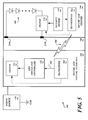
- FIGURE 5 is a block diagram of an exemplary security sensor 110 that includes a first transceiver 502 and a second transceiver 504 that communicate the authorization signal 506 in a wireless format.
- the wireless authorization signal 506 may be a radio frequency (RF) signal, an infrared (IR) signal, an optical signal, or other suitable wireless signal.
- the transceiver 502 is operable as a transmitter.
- the transceiver 502 transmits the authorization signal to the transceiver 504, which is operating as a receiver.
- the transceiver 502 may be a transmitter and/or the transceiver 504 may be a receiver, which are interchangeably referred to herein as a "transceiver" for convenience.
- the transceiver 504 then reformats the received wireless authorization signal 506 into a format that is receivable by the LED driver and controller 112, and communicates the authorization signal to the LED driver and controller 112, via a hardwire connection 508.
- the authorization signal is formatted as a binary signal with a unique identifier that identifies the secure LED fixture 106.
- a plurality of different models of secure LED fixtures 106 may vary based upon the number and/or type of LEDs 108 therein, or may vary based upon other characteristics, such as a particular lens and/or reflector. For example, more LEDs 108 may be used in models that are designed to emit a higher intensity light. Different models may have LEDs that emit different colors, or emit visible and/or infrared light. Different models may have different reflectors and/or lens that condition the emitted light in different ways.
- Such models may have substantially the same fixture structure or form, may have substantially the same type of electrical connectors and/or the location of the electrical connectors, and/or may have substantially the same type and location of the fasteners, to provide a compatible physical coupling to a secure LED fixture mounting 104.
- the intended purpose of the light emitted from the secure LED fixture 106 may be different.
- different models of the secure LED fixture 106 may have different intended light emission characteristics.
- a unique identifier may be part of the authorization signal such that the LED driver and controller 112 may discriminate between different models of secure LED fixtures 106. If the particular application requires a particular model of a secure LED fixture 106, then the LED driver and controller 112 may determine if the correct model of the secure LED fixture 106 has been coupled to its respective secure LED fixture mounting 104.
- the LED driver and controller 112 supplies power to the plurality of LEDs 108.
- the LED driver and controller 112 may generate and communicate an acknowledgement signal indicating that a compliant secure LED fixture 106 has been coupled to the secure LED fixture mounting 104.
- the transceiver 504 may be operable to communicate a wireless acknowledgement signal to the transceiver 502.
- the acknowledgement signal may be communicated via connectors 118, 116 ( FIGUREs 1 and 2 ).
- the acknowledgement signal may be used to confirm that a compliant model of the secure LED fixture 106 has been coupled to the secure LED fixture mounting 104.
- a suitable indication may then be provided based upon the acknowledgement signal.
- an indicator light or the like may be actuated in response to the acknowledgement signal to indicate that a compliant model of the secure LED fixture 106 has been coupled to the secure LED fixture mounting 104.
- Absence of the acknowledgement signal (when the acknowledgement signal is expected), or receipt of an acknowledgement signal that indicates presence of a noncompliant LED fixture may also be used to indicate that the noncompliant LED fixture has been coupled to the secure LED fixture mounting 104.
- a green light indicator may indicate that a compliant secure LED fixture 106 has been coupled to the secure LED fixture mounting 104
- a red light indicator may indicate that a noncompliant LED fixture has been coupled to the secure LED fixture mounting 104.
- a switch 510 may be included in the secure LED fixture 106 to interrupt power flow through the plurality of LEDs 108 if the acknowledgement signal indicates that a noncompliant model of the secure LED fixture 106 has been coupled to the secure LED fixture mounting 104.
- the switch 510 is electrically coupled to the plurality of LEDs 108.
- the switch 510 is communicatively coupled to the security sensor 110 and is configured to interrupt the power if no authorization signal is received from the security sensor.
- the switch 510 is communicatively coupled to the transceiver 502 and is configured to interrupt the power if no acknowledgement signal is received.
- a switch 512 residing in the secure LED fixture interface 102 may be operable to interrupt the power flow to the plurality of LEDs 108.
- the switch 512 may be communicatively coupled to and actuated by the transceiver 504.
- the switch 512 may be communicatively coupled to and actuated by the LED driver and controller 112.
- the switch 512 may be integrated into the LED driver and controller 112.
- the switch 512 may be controlled directly by the authorization signal, such as when the switch 512 is coupled to the connection 118 ( FIGUREs 1 and 2 ).
- the switch 512 may reside in any suitable location.
- the switch 512 may be a component of the power source 120, or may be coupled to an output of the power source 120.
- one or more components of the secure LED fixture interface 102 may be relocated into the secure LED fixture 106.
- the relocated critical component may be used by a security sensor 110 to generate the authorization signal and/or respond to an acknowledgement signal.
- Other embodiments may have the components of the secure LED fixture interface 102 configured in a different manner. Alternatively, or additionally, other components within the secure LED fixture interface 102 may be used to control the plurality of LEDs 108 in the secure LED fixture 106. In some embodiments, discrete groups of different pluralities of LEDs 108 may be separately operated, or operated in combination, such that light having specified characteristics is emitted from the secure LED fixture 106. Further, any suitable type of LED driver and controller 112 may be used to control the plurality of LEDs 108.
- Embodiments of the secure LED power system 100 may discontinue power to a noncompliant LED fixture in any suitable manner using any suitable means.
- the authorization signal may be communicated to the power source 120.
- the LED driver and controller 112 may generate and communicate a signal to the power source 120 to cause the power source 120 to interrupt power delivery to the noncompliant LED fixture.
- the exemplary embodiment of the secure LED power system 100 illustrates a combination of components (the transistor 202, the inductor 204, and the diode 206) residing in the secure LED fixture interface 102 that are configured to supply power to the plurality of LEDs 108.
- the components may be arranged in alternative configurations in other embodiments. Some components may be omitted, and/or other components not illustrated may be added in alternative embodiments. In other embodiments, one or more of the illustrated components may be located external to the secure LED fixture interface 102 as separate components and/or may be integrated into other systems or devices.
- the secure LED fixture mounting 104 was described as a separate component to facilitate physical coupling of the secure LED fixture 106 to an application device.
- the application device include aircraft, automobiles, and signs. Accordingly, the secure LED fixture interface 102 may reside elsewhere in the application device. Alternatively, the secure LED fixture mounting 104 and the secure LED fixture interface 102 may be implemented as a single integrated unit.
Landscapes
- Circuit Arrangement For Electric Light Sources In General (AREA)
Applications Claiming Priority (1)
| Application Number | Priority Date | Filing Date | Title |
|---|---|---|---|
| US12/258,136 US8159149B2 (en) | 2008-10-24 | 2008-10-24 | Systems and methods for security controlled LED lighting fixture |
Publications (3)
| Publication Number | Publication Date |
|---|---|
| EP2180764A2 true EP2180764A2 (de) | 2010-04-28 |
| EP2180764A3 EP2180764A3 (de) | 2014-04-02 |
| EP2180764B1 EP2180764B1 (de) | 2017-05-03 |
Family
ID=41572586
Family Applications (1)
| Application Number | Title | Priority Date | Filing Date |
|---|---|---|---|
| EP09173555.5A Not-in-force EP2180764B1 (de) | 2008-10-24 | 2009-10-20 | Systeme und Verfahren für sicherheitsgesteuerte LED-Leuchte |
Country Status (2)
| Country | Link |
|---|---|
| US (1) | US8159149B2 (de) |
| EP (1) | EP2180764B1 (de) |
Cited By (1)
| Publication number | Priority date | Publication date | Assignee | Title |
|---|---|---|---|---|
| WO2012110559A1 (de) * | 2011-02-17 | 2012-08-23 | Siteco Beleuchtungstechnik Gmbh | Led-leuchte |
Families Citing this family (11)
| Publication number | Priority date | Publication date | Assignee | Title |
|---|---|---|---|---|
| US20100093274A1 (en) * | 2008-10-15 | 2010-04-15 | Jian Xu | Fault-tolerant non-random signal repeating system for building electric control |
| TWI492657B (zh) * | 2008-11-17 | 2015-07-11 | 艾杜雷控股有限公司 | 安裝發光二極體驅動器的方法,發光二極體驅動器,發光二極體組合以及控制發光二極體組合之方法 |
| BRPI1006206A8 (pt) * | 2009-03-24 | 2017-12-19 | Koninl Philips Electronics Nv | Sistema de dispositivo de emissão de luz, acionador para um sistema de dispositovo de emissao de luz e sistema de controle externo |
| US8471731B2 (en) * | 2009-07-07 | 2013-06-25 | Honeywell International Inc. | Near end-of-life indication for light emitting diode (LED) aircraft navigation light |
| WO2012006515A1 (en) * | 2010-07-08 | 2012-01-12 | Lynk Labs, Inc. | Led lamp driver package method and apparatus |
| US8513955B2 (en) * | 2010-09-28 | 2013-08-20 | Tyco Electronics Corporation | SSL budgeting and coding system for lighting assembly |
| US20140035459A1 (en) * | 2012-08-06 | 2014-02-06 | Coast Cutlery Company | Portable illumination device with adjustable dimmer |
| US10039174B2 (en) | 2014-08-11 | 2018-07-31 | RAB Lighting Inc. | Systems and methods for acknowledging broadcast messages in a wireless lighting control network |
| US10531545B2 (en) | 2014-08-11 | 2020-01-07 | RAB Lighting Inc. | Commissioning a configurable user control device for a lighting control system |
| US9883567B2 (en) | 2014-08-11 | 2018-01-30 | RAB Lighting Inc. | Device indication and commissioning for a lighting control system |
| US10085328B2 (en) | 2014-08-11 | 2018-09-25 | RAB Lighting Inc. | Wireless lighting control systems and methods |
Family Cites Families (14)
| Publication number | Priority date | Publication date | Assignee | Title |
|---|---|---|---|---|
| US5748106A (en) * | 1996-03-25 | 1998-05-05 | Delco Electronics Corp. | Method and apparatus for controlling transponder signaling |
| US6777891B2 (en) | 1997-08-26 | 2004-08-17 | Color Kinetics, Incorporated | Methods and apparatus for controlling devices in a networked lighting system |
| US7358929B2 (en) | 2001-09-17 | 2008-04-15 | Philips Solid-State Lighting Solutions, Inc. | Tile lighting methods and systems |
| US6744223B2 (en) * | 2002-10-30 | 2004-06-01 | Quebec, Inc. | Multicolor lamp system |
| FI115948B (fi) * | 2003-06-06 | 2005-08-15 | Teknoware Oy | Valaisimen värilämpötilan säätö |
| US7193502B2 (en) * | 2004-03-06 | 2007-03-20 | Wayne-Dalton Corp. | Operating system and methods for seeding a random serial number for radio frequency control of a barrier operator's accessories |
| TWI245435B (en) | 2004-10-28 | 2005-12-11 | Premier Image Technology Corp | LED control apparatus and method |
| US20060220571A1 (en) * | 2005-03-31 | 2006-10-05 | Super Vision International, Inc. | Light emitting diode current control method and system |
| US7766518B2 (en) * | 2005-05-23 | 2010-08-03 | Philips Solid-State Lighting Solutions, Inc. | LED-based light-generating modules for socket engagement, and methods of assembling, installing and removing same |
| KR101186617B1 (ko) | 2006-02-21 | 2012-09-27 | 엘지이노텍 주식회사 | 엘이디 드라이브의 웨이브 노이즈 방지 장치 |
| US7218056B1 (en) * | 2006-03-13 | 2007-05-15 | Ronald Paul Harwood | Lighting device with multiple power sources and multiple modes of operation |
| PL2087776T3 (pl) | 2006-10-19 | 2015-05-29 | Philips Lighting North America Corp | Pracujące w sieci oprawy oświetleniowe oparte na diodach LED oraz sposoby zasilania i sterowania nimi |
| US7804256B2 (en) * | 2007-03-12 | 2010-09-28 | Cirrus Logic, Inc. | Power control system for current regulated light sources |
| CN102037278B (zh) * | 2008-03-20 | 2015-04-08 | 美国航易明国际有限公司 | 照明设备与装置 |
-
2008
- 2008-10-24 US US12/258,136 patent/US8159149B2/en not_active Expired - Fee Related
-
2009
- 2009-10-20 EP EP09173555.5A patent/EP2180764B1/de not_active Not-in-force
Cited By (2)
| Publication number | Priority date | Publication date | Assignee | Title |
|---|---|---|---|---|
| WO2012110559A1 (de) * | 2011-02-17 | 2012-08-23 | Siteco Beleuchtungstechnik Gmbh | Led-leuchte |
| EP3270663A1 (de) * | 2011-02-17 | 2018-01-17 | Siteco Beleuchtungstechnik GmbH | Austauschbares led-modul mit datenspeicher und led-betriebsgerät dafür |
Also Published As
| Publication number | Publication date |
|---|---|
| EP2180764A3 (de) | 2014-04-02 |
| US20100103665A1 (en) | 2010-04-29 |
| US8159149B2 (en) | 2012-04-17 |
| EP2180764B1 (de) | 2017-05-03 |
Similar Documents
| Publication | Publication Date | Title |
|---|---|---|
| EP2180764B1 (de) | Systeme und Verfahren für sicherheitsgesteuerte LED-Leuchte | |
| US8626318B2 (en) | Lamp device | |
| EP3501240B1 (de) | Beleuchtungsvorrichtung zur speisung aus einer netzstromversorgung und notstromversorgung | |
| US9035786B2 (en) | LED strobe light with peripheral pattern display | |
| US20120043909A1 (en) | LED Luminaires Power Supply | |
| CN104838727A (zh) | 用于固态照明设备的紧急照明系统和方法 | |
| CN111052871A (zh) | 用于嵌入式照明器材的智能装饰件 | |
| WO2007089581A2 (en) | Remote controlled led light bulb | |
| CN102111933A (zh) | Led驱动电路、相控调光器、led照明灯具、led照明设备以及led照明系统 | |
| CN102170723A (zh) | 固态照明系统 | |
| US20120119898A1 (en) | Vehicle light system | |
| US9980334B2 (en) | LED lighting system | |
| JP2018513537A (ja) | 照明システム | |
| CN101896951A (zh) | 用于交通灯的led驱动方法 | |
| EP2096899B1 (de) | Beleuchtungseinrichtung und Beleuchtungssystem für ein Fahrzeug | |
| CN104956772A (zh) | 用于操作led的装置 | |
| EP2531009A1 (de) | Menschliche Sensorvorrichtung, menschliches Sensorsystem und Beleuchtungssteuerungssystem | |
| EP2748900B1 (de) | Steuerschnittstellenmodul | |
| AU2022220212A1 (en) | Testing method and controller for controlling testing method | |
| WO2017129490A1 (en) | System and method for modular control | |
| CN105165125A (zh) | Led的操作装置 | |
| WO2006014069A1 (en) | Rear sensor system of car | |
| KR101465567B1 (ko) | 에스엠피에스 분리형 엘이디 신호등 무정전 시스템 | |
| US9190780B2 (en) | Power outlet capable of providing power in a controlled manner and method for configuring the same | |
| US20120091926A1 (en) | Electronic speed controller apparatus with signal dividing port device and control method thereof |
Legal Events
| Date | Code | Title | Description |
|---|---|---|---|
| PUAI | Public reference made under article 153(3) epc to a published international application that has entered the european phase |
Free format text: ORIGINAL CODE: 0009012 |
|
| 17P | Request for examination filed |
Effective date: 20091020 |
|
| AK | Designated contracting states |
Kind code of ref document: A2 Designated state(s): AT BE BG CH CY CZ DE DK EE ES FI FR GB GR HR HU IE IS IT LI LT LU LV MC MK MT NL NO PL PT RO SE SI SK SM TR |
|
| AX | Request for extension of the european patent |
Extension state: AL BA RS |
|
| PUAL | Search report despatched |
Free format text: ORIGINAL CODE: 0009013 |
|
| AK | Designated contracting states |
Kind code of ref document: A3 Designated state(s): AT BE BG CH CY CZ DE DK EE ES FI FR GB GR HR HU IE IS IT LI LT LU LV MC MK MT NL NO PL PT RO SE SI SK SM TR |
|
| AX | Request for extension of the european patent |
Extension state: AL BA RS |
|
| RIC1 | Information provided on ipc code assigned before grant |
Ipc: H05B 33/08 20060101AFI20140221BHEP |
|
| 17Q | First examination report despatched |
Effective date: 20140326 |
|
| R17C | First examination report despatched (corrected) |
Effective date: 20141007 |
|
| RAP1 | Party data changed (applicant data changed or rights of an application transferred) |
Owner name: HONEYWELL INTERNATIONAL INC. |
|
| GRAP | Despatch of communication of intention to grant a patent |
Free format text: ORIGINAL CODE: EPIDOSNIGR1 |
|
| INTG | Intention to grant announced |
Effective date: 20161222 |
|
| GRAS | Grant fee paid |
Free format text: ORIGINAL CODE: EPIDOSNIGR3 |
|
| GRAA | (expected) grant |
Free format text: ORIGINAL CODE: 0009210 |
|
| AK | Designated contracting states |
Kind code of ref document: B1 Designated state(s): AT BE BG CH CY CZ DE DK EE ES FI FR GB GR HR HU IE IS IT LI LT LU LV MC MK MT NL NO PL PT RO SE SI SK SM TR |
|
| REG | Reference to a national code |
Ref country code: GB Ref legal event code: FG4D |
|
| REG | Reference to a national code |
Ref country code: AT Ref legal event code: REF Ref document number: 891285 Country of ref document: AT Kind code of ref document: T Effective date: 20170515 Ref country code: CH Ref legal event code: EP |
|
| REG | Reference to a national code |
Ref country code: IE Ref legal event code: FG4D |
|
| REG | Reference to a national code |
Ref country code: DE Ref legal event code: R096 Ref document number: 602009045811 Country of ref document: DE |
|
| REG | Reference to a national code |
Ref country code: NL Ref legal event code: MP Effective date: 20170503 |
|
| REG | Reference to a national code |
Ref country code: AT Ref legal event code: MK05 Ref document number: 891285 Country of ref document: AT Kind code of ref document: T Effective date: 20170503 |
|
| REG | Reference to a national code |
Ref country code: LT Ref legal event code: MG4D |
|
| PG25 | Lapsed in a contracting state [announced via postgrant information from national office to epo] |
Ref country code: LT Free format text: LAPSE BECAUSE OF FAILURE TO SUBMIT A TRANSLATION OF THE DESCRIPTION OR TO PAY THE FEE WITHIN THE PRESCRIBED TIME-LIMIT Effective date: 20170503 Ref country code: GR Free format text: LAPSE BECAUSE OF FAILURE TO SUBMIT A TRANSLATION OF THE DESCRIPTION OR TO PAY THE FEE WITHIN THE PRESCRIBED TIME-LIMIT Effective date: 20170804 Ref country code: ES Free format text: LAPSE BECAUSE OF FAILURE TO SUBMIT A TRANSLATION OF THE DESCRIPTION OR TO PAY THE FEE WITHIN THE PRESCRIBED TIME-LIMIT Effective date: 20170503 Ref country code: HR Free format text: LAPSE BECAUSE OF FAILURE TO SUBMIT A TRANSLATION OF THE DESCRIPTION OR TO PAY THE FEE WITHIN THE PRESCRIBED TIME-LIMIT Effective date: 20170503 Ref country code: NO Free format text: LAPSE BECAUSE OF FAILURE TO SUBMIT A TRANSLATION OF THE DESCRIPTION OR TO PAY THE FEE WITHIN THE PRESCRIBED TIME-LIMIT Effective date: 20170803 Ref country code: AT Free format text: LAPSE BECAUSE OF FAILURE TO SUBMIT A TRANSLATION OF THE DESCRIPTION OR TO PAY THE FEE WITHIN THE PRESCRIBED TIME-LIMIT Effective date: 20170503 Ref country code: FI Free format text: LAPSE BECAUSE OF FAILURE TO SUBMIT A TRANSLATION OF THE DESCRIPTION OR TO PAY THE FEE WITHIN THE PRESCRIBED TIME-LIMIT Effective date: 20170503 |
|
| PG25 | Lapsed in a contracting state [announced via postgrant information from national office to epo] |
Ref country code: NL Free format text: LAPSE BECAUSE OF FAILURE TO SUBMIT A TRANSLATION OF THE DESCRIPTION OR TO PAY THE FEE WITHIN THE PRESCRIBED TIME-LIMIT Effective date: 20170503 Ref country code: BG Free format text: LAPSE BECAUSE OF FAILURE TO SUBMIT A TRANSLATION OF THE DESCRIPTION OR TO PAY THE FEE WITHIN THE PRESCRIBED TIME-LIMIT Effective date: 20170803 Ref country code: PL Free format text: LAPSE BECAUSE OF FAILURE TO SUBMIT A TRANSLATION OF THE DESCRIPTION OR TO PAY THE FEE WITHIN THE PRESCRIBED TIME-LIMIT Effective date: 20170503 Ref country code: SE Free format text: LAPSE BECAUSE OF FAILURE TO SUBMIT A TRANSLATION OF THE DESCRIPTION OR TO PAY THE FEE WITHIN THE PRESCRIBED TIME-LIMIT Effective date: 20170503 Ref country code: LV Free format text: LAPSE BECAUSE OF FAILURE TO SUBMIT A TRANSLATION OF THE DESCRIPTION OR TO PAY THE FEE WITHIN THE PRESCRIBED TIME-LIMIT Effective date: 20170503 Ref country code: IS Free format text: LAPSE BECAUSE OF FAILURE TO SUBMIT A TRANSLATION OF THE DESCRIPTION OR TO PAY THE FEE WITHIN THE PRESCRIBED TIME-LIMIT Effective date: 20170903 |
|
| PG25 | Lapsed in a contracting state [announced via postgrant information from national office to epo] |
Ref country code: RO Free format text: LAPSE BECAUSE OF FAILURE TO SUBMIT A TRANSLATION OF THE DESCRIPTION OR TO PAY THE FEE WITHIN THE PRESCRIBED TIME-LIMIT Effective date: 20170503 Ref country code: CZ Free format text: LAPSE BECAUSE OF FAILURE TO SUBMIT A TRANSLATION OF THE DESCRIPTION OR TO PAY THE FEE WITHIN THE PRESCRIBED TIME-LIMIT Effective date: 20170503 Ref country code: SK Free format text: LAPSE BECAUSE OF FAILURE TO SUBMIT A TRANSLATION OF THE DESCRIPTION OR TO PAY THE FEE WITHIN THE PRESCRIBED TIME-LIMIT Effective date: 20170503 Ref country code: EE Free format text: LAPSE BECAUSE OF FAILURE TO SUBMIT A TRANSLATION OF THE DESCRIPTION OR TO PAY THE FEE WITHIN THE PRESCRIBED TIME-LIMIT Effective date: 20170503 Ref country code: DK Free format text: LAPSE BECAUSE OF FAILURE TO SUBMIT A TRANSLATION OF THE DESCRIPTION OR TO PAY THE FEE WITHIN THE PRESCRIBED TIME-LIMIT Effective date: 20170503 |
|
| REG | Reference to a national code |
Ref country code: DE Ref legal event code: R097 Ref document number: 602009045811 Country of ref document: DE |
|
| PG25 | Lapsed in a contracting state [announced via postgrant information from national office to epo] |
Ref country code: IT Free format text: LAPSE BECAUSE OF FAILURE TO SUBMIT A TRANSLATION OF THE DESCRIPTION OR TO PAY THE FEE WITHIN THE PRESCRIBED TIME-LIMIT Effective date: 20170503 Ref country code: SM Free format text: LAPSE BECAUSE OF FAILURE TO SUBMIT A TRANSLATION OF THE DESCRIPTION OR TO PAY THE FEE WITHIN THE PRESCRIBED TIME-LIMIT Effective date: 20170503 |
|
| PLBE | No opposition filed within time limit |
Free format text: ORIGINAL CODE: 0009261 |
|
| STAA | Information on the status of an ep patent application or granted ep patent |
Free format text: STATUS: NO OPPOSITION FILED WITHIN TIME LIMIT |
|
| 26N | No opposition filed |
Effective date: 20180206 |
|
| REG | Reference to a national code |
Ref country code: DE Ref legal event code: R119 Ref document number: 602009045811 Country of ref document: DE |
|
| PG25 | Lapsed in a contracting state [announced via postgrant information from national office to epo] |
Ref country code: SI Free format text: LAPSE BECAUSE OF FAILURE TO SUBMIT A TRANSLATION OF THE DESCRIPTION OR TO PAY THE FEE WITHIN THE PRESCRIBED TIME-LIMIT Effective date: 20170503 Ref country code: MC Free format text: LAPSE BECAUSE OF FAILURE TO SUBMIT A TRANSLATION OF THE DESCRIPTION OR TO PAY THE FEE WITHIN THE PRESCRIBED TIME-LIMIT Effective date: 20170503 |
|
| REG | Reference to a national code |
Ref country code: CH Ref legal event code: PL |
|
| GBPC | Gb: european patent ceased through non-payment of renewal fee |
Effective date: 20171020 |
|
| REG | Reference to a national code |
Ref country code: IE Ref legal event code: MM4A |
|
| REG | Reference to a national code |
Ref country code: FR Ref legal event code: ST Effective date: 20180629 |
|
| PG25 | Lapsed in a contracting state [announced via postgrant information from national office to epo] |
Ref country code: LU Free format text: LAPSE BECAUSE OF NON-PAYMENT OF DUE FEES Effective date: 20171020 Ref country code: LI Free format text: LAPSE BECAUSE OF NON-PAYMENT OF DUE FEES Effective date: 20171031 Ref country code: CH Free format text: LAPSE BECAUSE OF NON-PAYMENT OF DUE FEES Effective date: 20171031 Ref country code: GB Free format text: LAPSE BECAUSE OF NON-PAYMENT OF DUE FEES Effective date: 20171020 Ref country code: DE Free format text: LAPSE BECAUSE OF NON-PAYMENT OF DUE FEES Effective date: 20180501 |
|
| REG | Reference to a national code |
Ref country code: BE Ref legal event code: MM Effective date: 20171031 |
|
| PG25 | Lapsed in a contracting state [announced via postgrant information from national office to epo] |
Ref country code: FR Free format text: LAPSE BECAUSE OF NON-PAYMENT OF DUE FEES Effective date: 20171031 Ref country code: BE Free format text: LAPSE BECAUSE OF NON-PAYMENT OF DUE FEES Effective date: 20171031 |
|
| PG25 | Lapsed in a contracting state [announced via postgrant information from national office to epo] |
Ref country code: MT Free format text: LAPSE BECAUSE OF NON-PAYMENT OF DUE FEES Effective date: 20171020 |
|
| PG25 | Lapsed in a contracting state [announced via postgrant information from national office to epo] |
Ref country code: IE Free format text: LAPSE BECAUSE OF NON-PAYMENT OF DUE FEES Effective date: 20171020 |
|
| PG25 | Lapsed in a contracting state [announced via postgrant information from national office to epo] |
Ref country code: HU Free format text: LAPSE BECAUSE OF FAILURE TO SUBMIT A TRANSLATION OF THE DESCRIPTION OR TO PAY THE FEE WITHIN THE PRESCRIBED TIME-LIMIT; INVALID AB INITIO Effective date: 20091020 |
|
| PG25 | Lapsed in a contracting state [announced via postgrant information from national office to epo] |
Ref country code: CY Free format text: LAPSE BECAUSE OF NON-PAYMENT OF DUE FEES Effective date: 20170503 |
|
| PG25 | Lapsed in a contracting state [announced via postgrant information from national office to epo] |
Ref country code: MK Free format text: LAPSE BECAUSE OF FAILURE TO SUBMIT A TRANSLATION OF THE DESCRIPTION OR TO PAY THE FEE WITHIN THE PRESCRIBED TIME-LIMIT Effective date: 20170503 |
|
| PG25 | Lapsed in a contracting state [announced via postgrant information from national office to epo] |
Ref country code: TR Free format text: LAPSE BECAUSE OF FAILURE TO SUBMIT A TRANSLATION OF THE DESCRIPTION OR TO PAY THE FEE WITHIN THE PRESCRIBED TIME-LIMIT Effective date: 20170503 |
|
| PG25 | Lapsed in a contracting state [announced via postgrant information from national office to epo] |
Ref country code: PT Free format text: LAPSE BECAUSE OF FAILURE TO SUBMIT A TRANSLATION OF THE DESCRIPTION OR TO PAY THE FEE WITHIN THE PRESCRIBED TIME-LIMIT Effective date: 20170503 |