EP2180821B1 - Energiezufuhr für eine flüssigkeitsabgabe-vorrichtung - Google Patents
Energiezufuhr für eine flüssigkeitsabgabe-vorrichtung Download PDFInfo
- Publication number
- EP2180821B1 EP2180821B1 EP08776631.7A EP08776631A EP2180821B1 EP 2180821 B1 EP2180821 B1 EP 2180821B1 EP 08776631 A EP08776631 A EP 08776631A EP 2180821 B1 EP2180821 B1 EP 2180821B1
- Authority
- EP
- European Patent Office
- Prior art keywords
- energy
- air
- source
- housing
- battery
- Prior art date
- Legal status (The legal status is an assumption and is not a legal conclusion. Google has not performed a legal analysis and makes no representation as to the accuracy of the status listed.)
- Active
Links
Images


Classifications
-
- A—HUMAN NECESSITIES
- A61—MEDICAL OR VETERINARY SCIENCE; HYGIENE
- A61M—DEVICES FOR INTRODUCING MEDIA INTO, OR ONTO, THE BODY; DEVICES FOR TRANSDUCING BODY MEDIA OR FOR TAKING MEDIA FROM THE BODY; DEVICES FOR PRODUCING OR ENDING SLEEP OR STUPOR
- A61M5/00—Devices for bringing media into the body in a subcutaneous, intra-vascular or intramuscular way; Accessories therefor, e.g. filling or cleaning devices, arm-rests
- A61M5/14—Infusion devices, e.g. infusing by gravity; Blood infusion; Accessories therefor
- A61M5/168—Means for controlling media flow to the body or for metering media to the body, e.g. drip meters, counters ; Monitoring media flow to the body
- A61M5/16804—Flow controllers
- A61M5/16822—Flow controllers by controlling air intake into infusion reservoir
-
- A—HUMAN NECESSITIES
- A61—MEDICAL OR VETERINARY SCIENCE; HYGIENE
- A61B—DIAGNOSIS; SURGERY; IDENTIFICATION
- A61B5/00—Measuring for diagnostic purposes; Identification of persons
- A61B5/145—Measuring characteristics of blood in vivo, e.g. gas concentration or pH-value ; Measuring characteristics of body fluids or tissues, e.g. interstitial fluid or cerebral tissue
- A61B5/14532—Measuring characteristics of blood in vivo, e.g. gas concentration or pH-value ; Measuring characteristics of body fluids or tissues, e.g. interstitial fluid or cerebral tissue for measuring glucose, e.g. by tissue impedance measurement
-
- A—HUMAN NECESSITIES
- A61—MEDICAL OR VETERINARY SCIENCE; HYGIENE
- A61M—DEVICES FOR INTRODUCING MEDIA INTO, OR ONTO, THE BODY; DEVICES FOR TRANSDUCING BODY MEDIA OR FOR TAKING MEDIA FROM THE BODY; DEVICES FOR PRODUCING OR ENDING SLEEP OR STUPOR
- A61M5/00—Devices for bringing media into the body in a subcutaneous, intra-vascular or intramuscular way; Accessories therefor, e.g. filling or cleaning devices, arm-rests
- A61M5/14—Infusion devices, e.g. infusing by gravity; Blood infusion; Accessories therefor
- A61M5/142—Pressure infusion, e.g. using pumps
- A61M5/14244—Pressure infusion, e.g. using pumps adapted to be carried by the patient, e.g. portable on the body
- A61M5/14248—Pressure infusion, e.g. using pumps adapted to be carried by the patient, e.g. portable on the body of the skin patch type
-
- A—HUMAN NECESSITIES
- A61—MEDICAL OR VETERINARY SCIENCE; HYGIENE
- A61M—DEVICES FOR INTRODUCING MEDIA INTO, OR ONTO, THE BODY; DEVICES FOR TRANSDUCING BODY MEDIA OR FOR TAKING MEDIA FROM THE BODY; DEVICES FOR PRODUCING OR ENDING SLEEP OR STUPOR
- A61M5/00—Devices for bringing media into the body in a subcutaneous, intra-vascular or intramuscular way; Accessories therefor, e.g. filling or cleaning devices, arm-rests
- A61M5/14—Infusion devices, e.g. infusing by gravity; Blood infusion; Accessories therefor
- A61M5/142—Pressure infusion, e.g. using pumps
- A61M5/145—Pressure infusion, e.g. using pumps using pressurised reservoirs, e.g. pressurised by means of pistons
- A61M5/155—Pressure infusion, e.g. using pumps using pressurised reservoirs, e.g. pressurised by means of pistons pressurised by gas introduced into the reservoir
-
- A—HUMAN NECESSITIES
- A61—MEDICAL OR VETERINARY SCIENCE; HYGIENE
- A61B—DIAGNOSIS; SURGERY; IDENTIFICATION
- A61B5/00—Measuring for diagnostic purposes; Identification of persons
- A61B5/145—Measuring characteristics of blood in vivo, e.g. gas concentration or pH-value ; Measuring characteristics of body fluids or tissues, e.g. interstitial fluid or cerebral tissue
- A61B5/1468—Measuring characteristics of blood in vivo, e.g. gas concentration or pH-value ; Measuring characteristics of body fluids or tissues, e.g. interstitial fluid or cerebral tissue using chemical or electrochemical methods, e.g. by polarographic means
- A61B5/1486—Measuring characteristics of blood in vivo, e.g. gas concentration or pH-value ; Measuring characteristics of body fluids or tissues, e.g. interstitial fluid or cerebral tissue using chemical or electrochemical methods, e.g. by polarographic means using enzyme electrodes, e.g. with immobilised oxidase
-
- A—HUMAN NECESSITIES
- A61—MEDICAL OR VETERINARY SCIENCE; HYGIENE
- A61M—DEVICES FOR INTRODUCING MEDIA INTO, OR ONTO, THE BODY; DEVICES FOR TRANSDUCING BODY MEDIA OR FOR TAKING MEDIA FROM THE BODY; DEVICES FOR PRODUCING OR ENDING SLEEP OR STUPOR
- A61M5/00—Devices for bringing media into the body in a subcutaneous, intra-vascular or intramuscular way; Accessories therefor, e.g. filling or cleaning devices, arm-rests
- A61M5/14—Infusion devices, e.g. infusing by gravity; Blood infusion; Accessories therefor
- A61M5/142—Pressure infusion, e.g. using pumps
- A61M2005/14204—Pressure infusion, e.g. using pumps with gas-producing electrochemical cell
-
- A—HUMAN NECESSITIES
- A61—MEDICAL OR VETERINARY SCIENCE; HYGIENE
- A61M—DEVICES FOR INTRODUCING MEDIA INTO, OR ONTO, THE BODY; DEVICES FOR TRANSDUCING BODY MEDIA OR FOR TAKING MEDIA FROM THE BODY; DEVICES FOR PRODUCING OR ENDING SLEEP OR STUPOR
- A61M5/00—Devices for bringing media into the body in a subcutaneous, intra-vascular or intramuscular way; Accessories therefor, e.g. filling or cleaning devices, arm-rests
- A61M5/14—Infusion devices, e.g. infusing by gravity; Blood infusion; Accessories therefor
- A61M5/142—Pressure infusion, e.g. using pumps
- A61M5/14244—Pressure infusion, e.g. using pumps adapted to be carried by the patient, e.g. portable on the body
- A61M2005/14264—Pressure infusion, e.g. using pumps adapted to be carried by the patient, e.g. portable on the body with means for compensating influence from the environment
-
- A—HUMAN NECESSITIES
- A61—MEDICAL OR VETERINARY SCIENCE; HYGIENE
- A61M—DEVICES FOR INTRODUCING MEDIA INTO, OR ONTO, THE BODY; DEVICES FOR TRANSDUCING BODY MEDIA OR FOR TAKING MEDIA FROM THE BODY; DEVICES FOR PRODUCING OR ENDING SLEEP OR STUPOR
- A61M5/00—Devices for bringing media into the body in a subcutaneous, intra-vascular or intramuscular way; Accessories therefor, e.g. filling or cleaning devices, arm-rests
- A61M5/14—Infusion devices, e.g. infusing by gravity; Blood infusion; Accessories therefor
- A61M5/142—Pressure infusion, e.g. using pumps
- A61M5/14244—Pressure infusion, e.g. using pumps adapted to be carried by the patient, e.g. portable on the body
- A61M2005/14268—Pressure infusion, e.g. using pumps adapted to be carried by the patient, e.g. portable on the body with a reusable and a disposable component
-
- A—HUMAN NECESSITIES
- A61—MEDICAL OR VETERINARY SCIENCE; HYGIENE
- A61M—DEVICES FOR INTRODUCING MEDIA INTO, OR ONTO, THE BODY; DEVICES FOR TRANSDUCING BODY MEDIA OR FOR TAKING MEDIA FROM THE BODY; DEVICES FOR PRODUCING OR ENDING SLEEP OR STUPOR
- A61M2205/00—General characteristics of the apparatus
- A61M2205/50—General characteristics of the apparatus with microprocessors or computers
-
- A—HUMAN NECESSITIES
- A61—MEDICAL OR VETERINARY SCIENCE; HYGIENE
- A61M—DEVICES FOR INTRODUCING MEDIA INTO, OR ONTO, THE BODY; DEVICES FOR TRANSDUCING BODY MEDIA OR FOR TAKING MEDIA FROM THE BODY; DEVICES FOR PRODUCING OR ENDING SLEEP OR STUPOR
- A61M2205/00—General characteristics of the apparatus
- A61M2205/58—Means for facilitating use, e.g. by people with impaired vision
- A61M2205/581—Means for facilitating use, e.g. by people with impaired vision by audible feedback
-
- A—HUMAN NECESSITIES
- A61—MEDICAL OR VETERINARY SCIENCE; HYGIENE
- A61M—DEVICES FOR INTRODUCING MEDIA INTO, OR ONTO, THE BODY; DEVICES FOR TRANSDUCING BODY MEDIA OR FOR TAKING MEDIA FROM THE BODY; DEVICES FOR PRODUCING OR ENDING SLEEP OR STUPOR
- A61M2205/00—General characteristics of the apparatus
- A61M2205/58—Means for facilitating use, e.g. by people with impaired vision
- A61M2205/582—Means for facilitating use, e.g. by people with impaired vision by tactile feedback
-
- A—HUMAN NECESSITIES
- A61—MEDICAL OR VETERINARY SCIENCE; HYGIENE
- A61M—DEVICES FOR INTRODUCING MEDIA INTO, OR ONTO, THE BODY; DEVICES FOR TRANSDUCING BODY MEDIA OR FOR TAKING MEDIA FROM THE BODY; DEVICES FOR PRODUCING OR ENDING SLEEP OR STUPOR
- A61M2205/00—General characteristics of the apparatus
- A61M2205/82—Internal energy supply devices
-
- A—HUMAN NECESSITIES
- A61—MEDICAL OR VETERINARY SCIENCE; HYGIENE
- A61M—DEVICES FOR INTRODUCING MEDIA INTO, OR ONTO, THE BODY; DEVICES FOR TRANSDUCING BODY MEDIA OR FOR TAKING MEDIA FROM THE BODY; DEVICES FOR PRODUCING OR ENDING SLEEP OR STUPOR
- A61M2207/00—Methods of manufacture, assembly or production
-
- A—HUMAN NECESSITIES
- A61—MEDICAL OR VETERINARY SCIENCE; HYGIENE
- A61M—DEVICES FOR INTRODUCING MEDIA INTO, OR ONTO, THE BODY; DEVICES FOR TRANSDUCING BODY MEDIA OR FOR TAKING MEDIA FROM THE BODY; DEVICES FOR PRODUCING OR ENDING SLEEP OR STUPOR
- A61M5/00—Devices for bringing media into the body in a subcutaneous, intra-vascular or intramuscular way; Accessories therefor, e.g. filling or cleaning devices, arm-rests
- A61M5/14—Infusion devices, e.g. infusing by gravity; Blood infusion; Accessories therefor
- A61M5/168—Means for controlling media flow to the body or for metering media to the body, e.g. drip meters, counters ; Monitoring media flow to the body
- A61M5/172—Means for controlling media flow to the body or for metering media to the body, e.g. drip meters, counters ; Monitoring media flow to the body electrical or electronic
- A61M5/1723—Means for controlling media flow to the body or for metering media to the body, e.g. drip meters, counters ; Monitoring media flow to the body electrical or electronic using feedback of body parameters, e.g. blood-sugar, pressure
Definitions
- Embodiments of the present disclosure relate generally to a system, a device and a method for sustained medical infusion of fluids and/or continuous monitoring of body analyte. More particularly, the present disclosure is related to a portable infusion patch-like device securable to the skin that, optionally, can also continuously monitor body analytes.
- a multi-component fluid dispensing and/or bodily analytes monitoring device is provided that is powered by a miniature highly efficient energy supply source.
- These drugs may be locally delivered to the subcutaneous tissue surrounding the incision scar to thus avoid systemic side effects of oral or intravenous administered analgesics.
- Other examples for applications of such pumps include using these pumps with cancer patients that require continuous delivery of chemotherapy medications via an open vein access port.
- the new concept included a remote controlled, skin securable (e.g., adherable) device with a housing having a bottom surface adapted for contact with the patient's skin, with a reservoir contained within the housing, and with an injection needle adapted for fluid communication with the reservoir.
- skin securable devices are designed to be replaced every 2-3 days similarly to the currently available pump infusion sets. However, most patients prefer to extend this period until reservoir emptying. This paradigm was described in U.S. Patents Nos.
- One of the reasons for the large size and heavy weight is the size and number of batteries that supply energy for maintaining a communication link between the skin securable device and the remote control unit, in addition to supplying energy to the energy-consuming components of the devices, such as the motor, display device, alarm, etc.
- a skin adherable device is disclosed. A large portion of the entire volume of this device is occupied by the batteries.
- four watch (button) batteries are needed to meet the dispenser energy requirements.
- the plane of the four button batteries is positioned perpendicularly to the longitudinal axis of the device and consequently the device is relatively thick (18mm) and bulky.
- these heavy and bulky batteries last for only three (3) days forcing the user to dispose of the device after three (3) days.
- a watch battery or button cell is a small form-factor battery designed for use in wrist watches, pocket calculators, hearing aids, and similar compact portable electronics products.
- the main advantage of watch batteries is their size, particularly their thickness. Unlike AA or even AAA cylindrical shape batteries, having diameters of at least 10 mm, watch batteries are flat, usually having a thickness of 3-5mm.
- a watch battery typically includes a single cell with nominal voltage between 1.5 and 3 volts. Common anode materials include zinc or lithium, and common cathode materials include manganese dioxide, silver oxide, and carbon monofluoride (or copper oxide). The cylindrical outer casing of these types of batteries forms part of the positive (+) terminal.
- the "C" type 3-V lithium cells and the "S” type 1.5 volt silver oxide cells are the most commonly used watch batteries.
- the dual function patch is composed of reusable and disposable parts, where, for example, the batteries reside within the disposable part. Similar to the single-piece "stand alone" dispensing device, this dual function device is relatively thin (thickness being not more than 15mm) and meets all energy requirements for the entire usage duration, e.g., for more than 3 days.
- a miniature and thin, portable, programmable fluid dispensing device (hereafter a "dispensing patch”) is disclosed that has a minimal space for an energy supply cell which meets the energy requirements of the device for at least a three-day operation period.
- a miniature and thin (e.g., less than 15mm) portable device for continuous monitoring of glucose contains a minimal space for an energy supply cell and meets the energy requirements of the device for at least a three-day operation period.
- the continuous monitoring device can be incorporated within the dispensing device, thus providing it with both sensing and dispensing capabilities.
- the device can dispense insulin according to monitored glucose levels within a closed loop system.
- a simple and inexpensive dispensing patch that is composed of two parts, a disposable part and a reusable part, is provided. After connecting the reusable and disposable parts, the assembled device has a thin profile with a relatively small footprint.
- a dispensing patch composed of two parts, a disposable part and a reusable part, which delivers fluid into the body of a patient is provided.
- An energy supply cell is contained within the disposable part and thus there is no need for any battery replacements. Thus, the user does not have to handle the batteries and needs not worry about battery replacement.
- a dispensing patch composed of two parts, a disposable part and a reusable part, that delivers fluid into the body of a patient.
- the disposable part contains an energy supply cell (e.g., a battery).
- the disposable part containing the energy supply cell can be disposed in any type trash receptacle, including regular home disposal systems, thus avoiding the use and maintenance of cumbersome toxic waste / biohazards containers.
- the present disclosure describes a miniature and thin (e.g., not more than about 20 mm and generally less than 15 mm) portable programmable fluid dispensing patch defining a space of, in some embodiments, less than 3 cm 3 for an energy supply cell. More particularly, the disclosure describes a small, low cost, portable dispensing patch comprising a disposable part and a reusable part.
- the power source is, in some embodiments, contained in the disposable part and includes one or more metal/air batteries.
- the metal/air battery may include a zinc/air button type battery.
- zinc/air batteries are the energy source for the dispensing patch because they are thin and have high specific energy density (i.e., such batteries are configured to store large amounts of charge relative to their weight and/or volume) to meet dispenser requirements.
- batteries When batteries are contained within the disposable part they can be disposed of approximately every three (3) days (e.g., by placing it in a non-biohazard garbage can).
- the production cost of the disposable part is a key issue in product profitability and thus a low cost of the zinc/air batteries is another advantage for their use.
- other battery types providing similar advantages may also be used in the device as described herein in the present disclosure.
- a single zinc/air battery is provided within the disposable part.
- the flat portion of the battery is aligned with the disposable part housing thus enabling a very thin device configuration.
- the electrical connectors are soldered directly to the battery cathode. This soldering avoids inadvertent disconnections from the battery.
- the device includes the following features:
- a high capacity capacitor e.g., at least 100 mF may be provided to meet momentary power/current requirements.
- the present disclosure provides a thin (e.g., the smallest dimension is less than about 15 mm) dispensing patch that contains at least one button (watch) battery, such as a silver oxide battery.
- a thin (e.g., the smallest dimension is less than about 15 mm) dispensing patch that contains at least one button (watch) battery, such as a silver oxide battery.
- a fluid dispensing patch contains a monitor for continuous monitoring of analyte.
- the fluid dispending patch is an insulin dispensing patch.
- the analyte that is monitored by the device is glucose.
- the device contains at least one button battery. In some embodiments, the device can dispense insulin according to monitored glucose levels, thus implementing a closed loop system.
- a thin (e.g., 15 mm) dispensing patch that contains at least one zinc/air battery.
- the disclosure also describes a method to enable oxygen entry into the device housing.
- a dispensing patch composed of two parts, a disposable part and a reusable part.
- a zinc/air battery may be placed within the disposable part (e.g., during manufacturing of the part) and thus battery replacement is not necessary.
- the zinc/air battery may include a seal that can be removed before, or after, parts pairing.
- a portable fluid dispensing device for infusing a fluid into the body of a user and/or for sensing an analyte within the body.
- the device includes at least one housing to retain a source of energy to energize the device, the source of energy comprising at least one electrochemical cell to produce electrical energy upon exposure of the cell to air, and a seal to prevent exposure of the at least one cell to air when the source of energy is not in use and to enable exposure of the at least one cell to air prior to energizing the device with the source of energy.
- the at least one housing includes an opening to provide access to the seal to enable actuation of the seal to control exposure of the at least one cell to air.
- Embodiments of the device may include one or more of the following features.
- the at least one housing of the device may be adapted to provide access to a tab of the seal to enable removal of the seal to cause the exposure of the at least one cell to the air.
- the device may further include a sensor module for sensing a bodily analyte level.
- the device may further include the source of energy held in the at least one housing.
- the seal may be secured to at least one surface of the source of energy through which air comes in contact with air-reactive parts of the source of energy.
- the seal may include a removable tab such that upon removal of the tab, the at least one cell of the source of energy is exposed to air.
- the at least one cell may includes at least one Zinc-Air cell.
- the source of energy may be configured as a button battery.
- the at least one housing may further include at least one air vent opening to enable air to be delivered to the source of energy, and a semi-permeable membrane placed in the at least one air vent opening, the semi-permeable membrane configured to enable entry of air into the at least one housing and to substantially prevent entry of at least some other materials into the at least one housing.
- the at least some other materials may include at least one of, for example, water and/or other liquids.
- the device may further include a second seal to prevent entry of air into the at least one housing through the at least one air vent opening when the device is not in operation.
- the second seal may cover the semi-permeable membrane to prevent entry of air into the at least one housing through the at least one air vent opening.
- the at least one housing may include a dedicated energy source cover to retain at least the energy source, and at least one second housing, the at least one second housing configured to receive and retain the dedicated energy source cover.
- the at least one housing may include a reusable part housing including a driving mechanism and a processor, and a disposable part housing including a reservoir to hold a therapeutic fluid and the source of energy.
- the source of energy may provide energy to the driving mechanism and/or processor.
- the disposable part may include a housing manufactured in a manner such that a portion of the housing retaining the source of energy is integrally formed around the source of energy source such that the source of energy cannot be removed.
- the source of energy may have a volume of less than about 3 cm 3 .
- the at least one housing may have a thickness of less than about 15 mm.
- a portable fluid dispensing device for infusing a fluid into the body of a user.
- the device includes at least one housing to retain at least a source of energy to energize the device, a pump to deliver a therapeutic fluid to the user, a driving mechanism to activate the pump, a processor to control the pump and/or driving mechanisms operations, and a capacitor to temporary store charge from the source of energy during a first time interval and discharge the stored charge to activate the driving mechanism during a second time interval.
- the first time interval is longer than the second time interval.
- Embodiments of the device may include any of the features of the first device described above, as well as any one of the following features.
- the first time interval may be at least 20 times longer than the second time interval.
- the first time interval may be about 50 times longer than the second time interval.
- the first time interval may overlap, at least in part, the second time interval.
- the device may further include the source of energy.
- the source of energy may comprise at least one electrochemical cell to produce electrical energy upon exposure of the cell to air.
- the at least one cell may include at least one Zinc-air cell.
- the source of energy may be configured as a button battery.
- a portable fluid dispensing device for infusing a fluid into the body of a user and/or for sensing an analyte within the body.
- the device includes a source of energy to energize the device, the source of energy comprising at least one electrochemical cell to produce electrical energy upon exposure of the cell to air.
- the device also includes at least one housing to retain the source of energy, and a seal to prevent exposure of the at least one cell to air when the source of energy is not in use and to enable exposure of the at least one cell to air prior to energizing the device with the said source of energy.
- the at least one housing is manufactured in a manner such that a portion of the at least one housing retaining the source oaf energy is integrally formed around the energy source such that the energy source cannot be removed.
- Embodiments of the device may include any of the features of any of the devices described herein, as well as any one of the following features.
- the at least one housing may include an opening to provide access to the seal to enable actuation of the seal to control exposure of the at least one cell to air.
- the seal may include a removable tab such that upon removal of the tab, the at least one cell of the source of energy is exposed to air.
- the tab may be positioned so that it is accessible through an opening in the at least one housing to enable removal of the tab through the opening.
- the seal may be secured to at least one surface of the source of energy through which air comes in contact with air-reactive parts of the source of energy.
- the at least one housing may include a reusable part housing including a driving mechanism and a processor, and a disposable part housing including a reservoir to hold a therapeutic fluid and the source of energy, the source of energy provides energy to the driving mechanism and/or processor.
- the device includes at least one housing to retain a source of energy to energize the device, the source of energy comprising at least one electrochemical cell to produce electrical energy upon exposure of the cell to air, and a seal to prevent exposure of the at least one cell to air when the source of energy is not in use and to enable exposure of the at least one cell to air prior to energizing the device with the said source of energy.
- the at least one housing includes an opening to provide access to the seal to enable actuation of the seal to control exposure of the at least one cell to air.
- a portable fluid dispensing device includes a source of energy to energize the device, the source of energy comprising at least one electrochemical cell to produce electrical energy upon exposure of the cell to air, at least one housing to retain the source of energy, and a seal to prevent exposure of the at least one cell to air when the source of energy is not in use and to enable exposure of the at least one cell to air prior to energizing the device with the said source of energy.
- the at least one housing is manufactured in a manner such that a portion of the at least one housing retaining the source of energy is integrally formed around the energy source such that the energy source cannot be removed.
- FIG. 1a a schematic diagram of an exemplary fluid delivery device, also referred to as an infusion pump, is shown.
- the infusion pump of FIG. 1a comprises a dispensing patch unit 10 which is securable (e.g., adherable) to a patient's body, and a remote control unit 40, which communicates with the patch unit 10.
- the patch unit 10 may be composed of a single part (as shown, for example, in FIG. 1b ) or of two parts (as shown, for example, in FIG. 1c ) that include a reusable part 100 and a disposable part 200.
- the patch unit 10 (also referred to as a dispensing unit) may employ different dispensing mechanisms, such as a syringe-type reservoir with a propelling plunger, a peristaltic positive displacement pump, etc.
- FIG 2a a schematic diagram of an exemplary fluid delivery device comprising a single-part patch unit 10, a cradle unit 20 and a remote control unit 40 is shown.
- the patch unit 10 is connected to the cradle unit 20 after the cradle unit 20 is secured (e.g., through some adhesive mechanisms) to a patient's skin 5.
- the patch unit 10 may be disconnected from, or reconnected to, the cradle unit 20 at the patient's discretion.
- a needle unit that includes a cannula and a penetrating member may be inserted through the cradle unit into the body of the patient.
- Fluid delivery can be programmed by a remote control unit 40 or programmed or controlled manually through at least one button 15 provided on the patch unit 10.
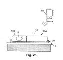
- FIG 2b a schematic diagram of an exemplary fluid delivery device comprising a two-part dispensing unit 10 with a reusable part 100 and a disposable part 200, a cradle unit 20 and a remote control unit 40 is shown.
- One or more manual buttons 15 may be located on the housing of the reusable part 100 of the patch unit 10.
- the configurations of the fluid delivery device comprising a patch unit, a cradle unit and a needle unit as detailed herein are described, for example, in co-owned Israeli Patent Application No. IL. 171813 , U.S. Publication No. 2007/0106218 , U.S. Application No. 11/706,606 and U.S. Provisional Patent Application Nos. 60/833,110 , 60/842,869 and 60/848,511 .
- One of the advantages of these configurations is that the relatively expensive components of a fluid delivery device may be deployed within the reusable part of the device while the relatively less expensive components, including, for example, a power source, may be accommodated within the disposable part.
- a dispensing unit i.e., patch unit
- a dispensing unit conforming to such configurations and arrangements (i.e., arrangement having a reusable and disposable parts) may render use of a therapeutic fluid dispensing device more economical for the manufacturer, for the device provider and/or for the patient.
- an inexpensive power source e.g., battery
- Such device arrangements also make it unnecessary to carry replacement batteries in addition to the infusion pump.
- replacement procedures to replace the power source are simplified in that replacement of the power source is reduced to replacing the entire disposable part, with the batteries contained therein, of the dispensing device (as shown, for example, in FIGS. 3 to 5 ) thus avoiding the need to utilize specialized tools, parts or skills to replace the actual power source.
- replacement of a battery may be performed separately and/or independently from the replacement of the disposable part.
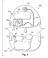
- FIG. 3 a schematic diagram of an exemplary peristaltic infusion pump with a disposable part 200 and a reusable part 100 is shown.
- the disposable part 200 and the reusable part 100 are depicted in FIG. 3 in a pre-attachment configuration (i.e., prior to attachment of the parts to each other).
- the disposable part comprises:
- the reusable part 100 may comprise:
- Each part may also have a coupling mechanism 211 to pair to the other part.
- a mechanism may include a magnet or any other known mechanical connector device such as clips, a clamp, a rail, a cog, etc.
- the electrical connectors can be combined with the coupling mechanism such that when mechanically attaching the two parts (e.g., the disposable part and the reusable part) together, the electrical components concomitantly electrically couple to the battery (e.g., via the various electrical connectors).
- Such connections are also available from Tyco Electronics Corporation.
- FIG. 4 a schematic diagram of an exemplary peristaltic infusion pump 10 with disposable part 200 and the reusable part 100 attached to each other is shown.
- the infusion pump 10 also includes a sensor 120 to monitor a body analyte (e.g., glucose). Fluid delivery can be adjusted based on the monitored body analyte to thus implement a semi, or fully, closed-loop system.
- a body analyte e.g., glucose
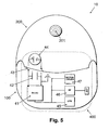
- FIG. 5 a schematic diagram of an exemplary two-part infusion pump, including a block diagram depicting the electrical arrangement housed in the reusable part, is shown.
- an electrical circuit 400 is closed by electrically connecting the power source 44, to the other components of the electrical circuit.
- the power source may include one or more button batteries such as, for example, zinc/air batteries.
- the electrical circuit includes a motor driver 47 and a CPU 45 to control and monitor the activity of the pump.
- the CPU 45 may be placed on a Printed-Circuit Board (PCB), as shown, for example, in Figures 3 and 4 as the element marked as reference numeral 116.
- PCB Printed-Circuit Board
- Also connected to the electrical circuit are a receiver 46 and a DC-DC step up converter 41.
- the connectors that include housings and tabs (respectively marked, in Figures 3 and 4 , as reference numeral 112 and 213) that may implement the functionality of the switches 43 (shown in FIG. 5 ) which switch on the electrical components of the infusion pump upon mechanical connection of the disposable and the reusable parts.
- the outlet port 201 to deliver the therapeutic fluid.
- the electrical arrangement of the circuit 400 implemented in the reusable part includes a capacitor 42, such as a high capacity capacitor of more than 100mF capacity.
- the capacitor has a capacity of at least 180 mF capacitor.
- the capacitor is configured to accumulate sufficient charge so that a higher current than what can be generated by the battery by itself may be provided to power components requiring that higher current level. The capacitor is charged by the battery for a particular period of time and then releases the charge over a relatively short period of time.
- the relation between the time during which the capacitor is charged with current supplied by the power source (e.g., the battery) and the time during which the capacitor is discharged may be controlled, for example, by the CPU 45 and/or by a suitable electrical circuit arrangement to control the charge and discharge periods (e.g., selecting resistance and capacitance values introduced into the arrangement to affect the charge and discharge periods of the capacitor).
- the time duration during which the capacitor is loaded may be 490 milliseconds, and the time duration during which the capacitor is discharged may be 20 milliseconds. Under these circumstances, if the battery's output current is 10mA, the capacitor discharge output is about 500mA, the discharge time would therefore be approximately 50 shorter than the charging time to charge the capacitor.
- the time interval for charging the capacitor may be at least twenty (20) times longer than the time interval to discharge the capacitor.
- the time interval to charge the capacitor may overlap, at least in part, the time interval to discharge the capacitor.
- fuel cells e.g., zinc air batteries
- zinc/air batteries enables manufacturing of relatively small dimensioned patch units.
- the smallest dimension of standard AAA battery is 10.5 mm (the battery's diameter)
- the smallest dimension of standard zinc/air battery e.g., DA10 or DA312 made by DURACELLTM
- the larger battery dimensions of standard AA and/or AAA batteries result in heavier and larger infusion patches and/or insulin pumps (because larger housings would be required to accommodate such batteries), and also increase the costs of these devices.
- Typical insulin pump devices weigh about 85 g and have a height of about 15mm.
- some embodiments of infusion pumps in described herein weigh about 20g and are less than 15mm in height and in some embodiments the smallest dimension is less than 15mm.
- Zinc-air batteries also called “zinc-air fuel cells” are non-rechargeable, electrochemical batteries powered by the oxidation of zinc with oxygen from the air. These batteries have very high energy densities and are relatively inexpensive to produce. They are mainly used in hearing aids as described, for example, in U.S. Patents Nos. 5,591,541 , 5,607,796 , 5,662,717 , 5,733,676 and 5,804,327 .
- Zinc-air cells generally work like conventional batteries, i.e., the batteries generate electrical power from chemical reactions. However, instead of packing the necessary materials (ingredients) inside the cell, zinc-air batteries get one of their main reactants, namely, oxygen, from the outside air.
- zinc-air cells contain no toxic compounds and are neither overly reactive nor flammable. Thus, zinc-air batteries can be recycled and safely disposed of.
- Other advantages of zinc air batteries includes:
- FIGS. 6a and 6b cross-sectional schematic diagrams of an exemplary zinc/air battery 50 are shown.
- FIG. 6a shows the battery in active mode, without a seal, thus enabling the chemical reaction that consumes O 2(g) , found in the ambient air, to occur.
- FIG. 6b shows the battery 50 as it is provided by the manufacturer with its cathode chamber sealed with a sealing mechanism 61 (e.g., a peelable seal).
- a sealing mechanism 61 e.g., a peelable seal
- the battery 50 includes a cell having a zinc anode chamber 51 in which zinc is oxidized upon the introduction of air, which includes oxygen, into the air cathode chamber 57 in which reduction of oxygen to water takes place, thus creating an electrical potential difference.
- Oxygen can enter the air cathode chamber through at least one air access opening 55 provided in a wall of the air cathode chamber. The opening is required because the reduction reaction requires a constant supply of oxygen.
- the battery is provided by the manufacturer with its air cathode sealed, thus preventing the activation of the battery while it being shipped and stored.
- the seal 61 (or some other type of sealing mechanism) that controls the entry of oxygen into the cathode chamber of the cell may be actuated to cause air to enter the cell.
- the seal 61 includes a removable tab that covering the opening 55, the seal is removed by pulling its tab 63 before the battery can be used to supply energy.
- the two chambers are separated by a barrier 56 and each of the chambers is enclosed in a separate housing (i.e., a shell or a can): an anode can 54 and a cathode can 53.
- a separate housing i.e., a shell or a can
- the cans are isolated from each other by a gasket 52 to prevent discharge
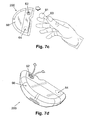
- FIGS. 7a to 7d views depicting operation of exemplary sealing mechanisms that control air entry into energy sources (e.g., batteries) are shown.
- energy sources e.g., batteries
- the figures show the removal of a battery's seal 61 by pulling the seal's tab 63.
- the seal isolates the cathode can from ingress of oxygen, thus preventing the unnecessary (i.e., premature) oxidation of the zinc in the battery prior to commencing use of the battery to power, for example, a dispensing device. Therefore, the battery 50 remains inactive as long as it is sealed. While the battery is inactive, its shelf life is significantly prolonged, thus also extending the shelf life of the disposable part.
- FIG. 7a shows a sealing mechanism that includes a peelable seal (for example, a circular cover that covers substantially the entire surface area of the cathode or of the opening through which air would enter the battery) attached to a pull tab.
- the battery's seal is attached directly to the battery, and may be placed onto the battery by the manufacturer of the battery. This configuration requires only that the battery be connected to the infusion pump with no further processing.
- the battery may be placed in the infusion pump during the manufacturing (e.g., assembly) process to produce the pump such that the infusion pump already includes the scaled battery in condition for immediate use upon removal of the seal.
- the power (energy) source is integrally connected to the infusion pump (e.g., to the disposable part of a two-part infusion pumps) such that it cannot easily, or at all, be removed or replaced.
- the sealed power source may be connected to the infusion pump by soldering.
- an opening for the seal's tab (numeral 65 in FIG. 12b ) may be left in the housing (cover 66) of the disposable part.
- the opening would thus provide access to the sealing mechanism of the energy source that controls the entry of air to the battery, and would enable actuation of the sealing mechanism, prior to commencing operation of the patch unit, to enable entry of air to the battery.
- the tab 63 is placed outside the cover while the battery 50 is placed within the disposable part in a dedicated cover 64 (also referred as battery's housing).
- the opening would enable the removal of the seal 61 by pulling the tab.
- ingress of oxygen into the battery is enabled and the battery is activated (as shown, for example, in Figs. 7c and 7d ).
- a selective membrane 62 may be placed in an opening to enable ingress of oxygen to the battery. Further details regarding the use of such a selective membrane is provided, for example, in the commonly-owned provisional application No. 60/961,382 , entitled “Vented Dispensing Device and Method” and the non-provisional application entitled “Vented Dispensing Device and Method", being filed on the same day as the current application, the contents of both of which are hereby incorporated by reference in their entireties.
- the selective membrane also referred to as breathable membrane
- the membrane may be made from waterproof materials and/or waterproof fabrics such as, for example, waterproof/breathable fabrics that provide gas diffusion through the membrane but repel water.
- waterproof materials and/or waterproof fabrics such as, for example, waterproof/breathable fabrics that provide gas diffusion through the membrane but repel water.
- An example of such a suitable fabric is GORE-TEXTM, described, for example, in U.S. Patent No. 4,194,041 .
- the membrane is covered with a seal that is removed just before use of the battery begins.
- the seal is made of impermeable material, which prevents oxygen ingress and thus gives the battery prolonged shelf life.
- FIG. 7b a view of another exemplary embodiment of an infusion pump with a sealing mechanism is depicted.
- a seal is placed on the external side of the selective membrane (e.g., at the exterior of the infusion pump).
- the cover should be air tight to prevent energy depletion of the battery.
- the infusion pump can be packaged in a substantially air tight enclosure to enable the sealing of the battery.
- FIGS. 7c and 7d show the disposable part of the device after the removal of the seal.
- the seal's tab has been pulled by the user and thus oxygen is free to move from the exterior of the infusion pump to the battery 50 through the membrane 62 (as shown in FIG. 7d ).
- FIG. 8 a view illustrating an exemplary battery insertion approach is shown.
- the batteries are provided separately, i.e., not as an integral component of the cradle (as shown, for example, in FIG. 11 ) or in the disposable part of the device (as shown, for example, in FIGS. 3 to 5 and 7a to 7d ). Therefore, in the illustrated embodiment of FIG. 8 , the batteries are inserted into the pump and electrically connected thereto manually.
- FIG. 8 shows a single battery 50 without a seal or other type of scaling mechanism, being positioned in a dedicated pocket 72 (or housing) that is attachable to the external cover of the reusable part.
- the pocket can be detached from the cover 71 of the reusable part 100, when replacing the battery.
- the wheel 73 of the peristaltic mechanism shown also in FIGS. 3 and 4 where it is indicated by reference numeral 114).
- the infusion pump 900 is implemented as a semi-closed loop and/or closed-loop system to sense analytes level (e.g., senses glucose) and dispense therapeutic fluid (e.g., insulin).
- the system includes one or more energy sources (e.g., button batteries) that are used to supply the energy needs of the closed loop system.
- energy sources e.g., button batteries
- the system 900 includes two parts: a reusable part 950 containing the relatively more expensive components of the system, such as the CPU and other electrical components 92, a motor and, a driving mechanism (as shown, for example, in FIG. 4 ).
- the power for the electrical components, including one or more sensors 93, is supplied by one or more button batteries 99, such as zinc/air button batteries.
- the batteries may be placed in the disposable part 960 and are electrically connected to the electrical components by a set of wires 94.
- Plugs 95 are used to connect the reusable part to the disposable part. The plugs connect the main electric components of the system to the power source and also connect the probes 97 to the one or more sensors 93.
- the sensor 93 receives signals related to the bodily analyte (e.g., glucose) concentrations from one or more probes 97 and processes the signals to provide data regarding the bodily analyte concentrations.
- the sensor 93 may in integrate with the CPU and /or other electrical components 92.
- the sensor can be connected to the plugs by any standard mechanism, including wires and/or optical fiber 96.
- the one or more probes 97 are coupled to a cannula which provides a passage to the user's body (as shown, for example, in FIG. 11 ).
- the system for sensing analyte and dispensing therapeutic fluid is attached to the user's skin by a cradle 20.
- the cradle may be attached to the user's skin 5 by adhesive 91.
- the energy requirements of a combined sensing and dispensing device are met by button batteries.
- the energy requirements of a device with only sensing capacity are also met by button batteries.
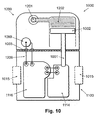
- FIG. 10 a schematic diagram of an exemplary embodiment of a two-part infusion pump 1000 is shown.
- the infusion pump 1000 delivers therapeutic fluid by a propelling plunger mechanism, similar to the mechanism disclosed, for example, in PCT patent application No. PCT/IL08/000641 , entitled “A positive displacement pump", filed May 11, 2008.
- the infusion pump 1000 comprises two parts: a reusable part 1100 and a disposable part 1200.
- the infusion pump includes:
- connection 1003 can be implemented by simple metal (or other conducting material) plates that are pressed together when the two parts of the infusion pump are assembled together. Further details about electrically connecting the reusable and disposable parts are also provided, for example, with respect to FIGS. 3 and 4 .
- FIG. 11 a schematic diagram of a peristaltic-type two-part infusion pump is shown. At least one button battery is used as a power source 1099 for the infusion pump 10. In some embodiments, some or all of the batteries are placed in a cradle 20 that is secured to the user's skin 5. The power source is electrically connected to the electrical components 116 and to the motor and driving mechanism 115 of the reusable part 100 using a plug and socket connections 1103. FIG. 11 also shows a cannula 1104 that is used for delivering a therapeutic fluid to the user's body.
- FIGS. 12a to 12d schematic diagrams of exemplary configurations for connecting a battery to infusion pumps are shown.
- FIG 12d depicts a battery and the wiring 209 that electrically connect the battery to the electrical circuitry of the infusion pump(s).
- FIGS. 12a and 12b depict a dedicated cover (housing) 60 for a button battery 50 (as was previously described herein).
- the battery is connected to the electrical components of the device via connectors, namely, cathode connectors 203 and an anode connector 205.
- the connectors are located, in some embodiments, on the principal flat surfaces (e.g., upper and/or lower flat surfaces) of the button battery and thus provide large contact areas.
- the dedicated cover 64 also includes a selective membrane 62 (also referred to as "semi permeable membrane,” or breathable membrane”). The dedicated cover 64 isolates and protects the battery, and possibly other components of the infusion pump, from the environment.
- the insulation cover may be made an integral part of these components as shown, for example, in FIGS. 7a to 7d .
- the selective membrane 62 has a selective permeability. It thus protects the battery from the entrance of harmful materials such as water and other liquids, but enables oxygen transfer to the battery. Oxygen transfer to the battery's cathode prior to activating the infusion pump is prevented by a sealing mechanism, e.g., a seal 61.
- the seal can be placed on the selective membrane as shown in FIG. 12a , or it may be left directly on the battery as provided by the manufacturer as shown in FIG. 12b .
- an opening 65 to enable access to the sealing mechanism is left in the cover so that the seal's tab, for example, can be pulled to lift the seal.
- the battery 50 can be soldered, or otherwise attached, during the pump manufacturing process to the electrical circuit through a set of wires 209 to avoid inadvertent disconnections.
- the battery may be connected to the electrical circuit using a high contact area connector. For example, when a connection area between the battery's cathode and the connector, is more than 10 mm 2 , e.g., between 18 mm 2 and 25 mm 2 , the service life of the battery is significantly increased.
- the connection area may be increased by applying multiple standard connections, a grid of wires, a perforated plate or any other mechanism to electrically connect the battery without adversely affecting air ingress.
- FIG. 12c shows a single connection 203 to the battery cathode 53.
- FIG. 12d shows more than one connection, for example three (3) connections 203, which can substantially increase the battery's service life.
- the connection can be to the same wire (not shown), or each connection can be associated with a separated wire 209. There may be fewer connections in circumstances where the contact area is sufficiently large, e.g., greater than 15 mm 2 . It will be appreciated that for the purpose of connecting the battery to activate the electrical components of the infusion pump, the anode side 54 of the battery also has to be electrically connected.
- FIG. 12e a schematic diagram, including the electrical arrangement, of an exemplary embodiment of a disposable 200 and reusable 100 parts of an infusion device 10 attached to each other is shown.
- the electrical circuit 400 is electrically closed once the battery 50 is connected to the other components of the electrical circuit.
- the battery may be soldered to wires 209 as shown, for example, in FIG. 12d .
- the battery may be pressed against connectors to enable electrical coupling with other electronics of the infusion device.
Landscapes
- Health & Medical Sciences (AREA)
- Life Sciences & Earth Sciences (AREA)
- Heart & Thoracic Surgery (AREA)
- Engineering & Computer Science (AREA)
- Biomedical Technology (AREA)
- General Health & Medical Sciences (AREA)
- Veterinary Medicine (AREA)
- Public Health (AREA)
- Animal Behavior & Ethology (AREA)
- Anesthesiology (AREA)
- Vascular Medicine (AREA)
- Hematology (AREA)
- Physics & Mathematics (AREA)
- Dermatology (AREA)
- Pathology (AREA)
- Surgery (AREA)
- Molecular Biology (AREA)
- Medical Informatics (AREA)
- Biophysics (AREA)
- Optics & Photonics (AREA)
- Emergency Medicine (AREA)
- Infusion, Injection, And Reservoir Apparatuses (AREA)
- Sampling And Sample Adjustment (AREA)
- Hybrid Cells (AREA)
Claims (14)
- Vorrichtung (10) zum Ausgeben eines therapeutischen Fluids zum Infundieren eines Fluids in den Körper eines Benutzers und optional zum Erfassen eines Analyts in dem Körper, wobei die Vorrichtung Folgendes umfasst:wenigstens ein Gehäuse zur Aufnahme einer Energiequelle zum Bestromen der Vorrichtung, wobei das wenigstens eine Gehäuse Folgendes umfasst:einen wiederverwendbaren Gehäuseteil, der einen Prozessor (116) umfasst; undeinen wegwerfbaren Gehäuseteil, der Folgendes beinhaltet:ein Reservoir (202) zum Aufnehmen eines therapeutischen Fluids;wobei die Energiequelle wenigstens eine elektrochemische Zelle (50) zum Erzeugen von elektrischer Energie bei Kontakt der Zelle mit Luft umfasst;eine Dichtung (61) zum Verhindern von Luftkontakt der wenigstens einen Zelle (50), wenn die Energiequelle nicht im Gebrauch ist, und zum Ermöglichen von Luftkontakt der wenigstens einen Zelle (50) vor dem Bestromen der Vorrichtung mit der Energiequelle; undeine Öffnung zum Bereitstellen von Zugang zu der Dichtung (61), um eine Betätigung der Dichtung zum Regulieren des Luftkontakts der wenigstens einen Zelle zu ermöglichen,dadurch gekennzeichnet, dass der wiederverwendbare Gehäuseteil ferner einen Antriebsmechanismus (115) umfasst, und dass das wenigstens eine Gehäuse ferner Folgendes umfasst:wenigstens eine Lüftungsöffnung, um Luftzufuhr zu der Energiequelle zu ermöglichen; undeine teildurchlässige Membran (62), die in der wenigstens einen Lüftungsöffnung platziert ist, wobei die teildurchlässige Membran so konfiguriert ist, dass sie den Eintritt von Luft in das wenigstens eine Gehäuse zulässt und den Eintritt wenigstens einiger anderer Materialien in das wenigstens eine Gehäuse im Wesentlichen verhindert.
- Vorrichtung (10) nach Anspruch 1, wobei die Öffnung in dem wegwerfbaren Gehäuseteil Zugang zu einer mit der Dichtung (61) assoziierten Zunge (63) bietet, wobei die Zunge (63) so konfiguriert ist, dass sie die Dichtung (61) entfernt, so dass die wenigstens eine Zelle (50) mit Luft in Kontakt kommt.
- Vorrichtung (10) nach Anspruch 1, wobei die Dichtung (61) an wenigstens einer Fläche der Energiequelle befestigt ist, durch die Luft mit mit Luft reagierenden Teilen der Energiequelle in Kontakt kommt.
- Fluidausgabevorrichtung (10) nach Anspruch 1, wobei die wenigstens eine Zelle (50) wenigstens eine Zink-Luft-Zelle beinhaltet.
- Vorrichtung (10) nach Anspruch 1, wobei die wenigstens einigen anderen Materialien Wasser und/oder andere Flüssigkeiten beinhalten.
- Vorrichtung (10) nach Anspruch 1, die ferner eine zweite Dichtung umfasst, wobei die zweite Dichtung die teildurchlässige Membran (62) bedeckt, um das Eintreten von Luft in das wenigstens eine Gehäuse durch die wenigstens eine Lüftungsöffnung zu verhindern, wenn die Vorrichtung nicht im Betrieb ist.
- Vorrichtung (10) nach Anspruch 1, wobei der wegwerfbare Gehäuseteil Folgendes umfasst:eine dedizierte Energiequellenabdeckung, um wenigstens die Energiequelle aufzunehmen; undwenigstens ein zweites Gehäuse, wobei das wenigstens eine zweite Gehäuse zum Aufnehmen und Halten der dedizierten Energiequellenabdeckung konfiguriert ist.
- Vorrichtung (10) nach Anspruch 1, wobei ein Teil des die Energiequelle aufnehmenden wegwerfbaren Gehäuseteils einstückig um die Energiequelle herum ausgebildet ist, so dass die Energiequelle nicht entfernt werden kann.
- Vorrichtung (10) nach Anspruch 1, wobei das wenigstens eine Gehäuse eine Dicke von weniger als etwa 15 mm hat.
- Vorrichtung (10) nach Anspruch 1, wobei der wiederverwendbare Gehäuseteil ferner einen Kondensator (42) zum vorübergehenden Speichern einer Ladung von der Energiequelle während eines ersten Zeitintervalls und zum Entladen der gespeicherten Energie zum Aktivieren des Antriebsmechanismus (115) während eines zweiten Zeitintervalls umfasst, und wobei das erste Zeitintervall länger ist als das zweite Zeitintervall.
- Vorrichtung (10) nach Anspruch 10, wobei das erste Zeitintervall wenigstens 20 Mal länger ist als das zweite Zeitintervall.
- Vorrichtung (10) nach Anspruch 10, wobei das erste Zeitintervall wenigstens teilweise mit dem zweiten Zeitintervall überlappt.
- Vorrichtung (10) nach Anspruch 4, wobei die die Zink-Luft-Zelle umfassende Energiequelle recyclierbar ist und/oder gefahrlos in einem Behälter für nicht biogefährliche Abfälle entsorgt werden kann.
- Vorrichtung (10) nach Anspruch 4, wobei die die Zink-Luft-Zelle umfassende Energiequelle wenigstens eines der folgenden beinhaltet: nichttoxische Materialien, nicht zu sehr reaktive Materialien und nicht flammbare Materialien.
Applications Claiming Priority (4)
| Application Number | Priority Date | Filing Date | Title |
|---|---|---|---|
| US96152807P | 2007-07-20 | 2007-07-20 | |
| US96148407P | 2007-07-20 | 2007-07-20 | |
| US96138207P | 2007-07-20 | 2007-07-20 | |
| PCT/IL2008/000999 WO2009013734A2 (en) | 2007-07-20 | 2008-07-20 | Energy supply for fluid dispensing device |
Publications (2)
| Publication Number | Publication Date |
|---|---|
| EP2180821A2 EP2180821A2 (de) | 2010-05-05 |
| EP2180821B1 true EP2180821B1 (de) | 2014-05-07 |
Family
ID=40029020
Family Applications (3)
| Application Number | Title | Priority Date | Filing Date |
|---|---|---|---|
| EP08776632.5A Active EP2178583B1 (de) | 2007-07-20 | 2008-07-20 | Belüftete Spendevorrichtung |
| EP08776630A Withdrawn EP2180910A2 (de) | 2007-07-20 | 2008-07-20 | Kollabierbarer behälter zur verwendung mit einer abgabevorrichtung |
| EP08776631.7A Active EP2180821B1 (de) | 2007-07-20 | 2008-07-20 | Energiezufuhr für eine flüssigkeitsabgabe-vorrichtung |
Family Applications Before (2)
| Application Number | Title | Priority Date | Filing Date |
|---|---|---|---|
| EP08776632.5A Active EP2178583B1 (de) | 2007-07-20 | 2008-07-20 | Belüftete Spendevorrichtung |
| EP08776630A Withdrawn EP2180910A2 (de) | 2007-07-20 | 2008-07-20 | Kollabierbarer behälter zur verwendung mit einer abgabevorrichtung |
Country Status (7)
| Country | Link |
|---|---|
| US (7) | US8491529B2 (de) |
| EP (3) | EP2178583B1 (de) |
| JP (1) | JP2010534084A (de) |
| CN (1) | CN101815464A (de) |
| AU (1) | AU2008278638A1 (de) |
| DK (2) | DK2180821T3 (de) |
| WO (3) | WO2009013733A2 (de) |
Families Citing this family (105)
| Publication number | Priority date | Publication date | Assignee | Title |
|---|---|---|---|---|
| US6850788B2 (en) | 2002-03-25 | 2005-02-01 | Masimo Corporation | Physiological measurement communications adapter |
| EP1617888B1 (de) | 2003-04-23 | 2019-06-12 | Valeritas, Inc. | Hydraulisch aktivierte pumpe für langzeitabgabe von medikamenten |
| WO2006014425A1 (en) | 2004-07-02 | 2006-02-09 | Biovalve Technologies, Inc. | Methods and devices for delivering glp-1 and uses thereof |
| US7905868B2 (en) * | 2006-08-23 | 2011-03-15 | Medtronic Minimed, Inc. | Infusion medium delivery device and method with drive device for driving plunger in reservoir |
| CN103239773B (zh) | 2006-03-30 | 2015-08-26 | 瓦莱里塔斯公司 | 多筒式流体递送器械 |
| US8303275B2 (en) * | 2006-12-07 | 2012-11-06 | Seiko Epson Corporation | Micropump, tube unit, and control unit |
| WO2008136845A2 (en) | 2007-04-30 | 2008-11-13 | Medtronic Minimed, Inc. | Reservoir filling, bubble management, and infusion medium delivery systems and methods with same |
| US7963954B2 (en) | 2007-04-30 | 2011-06-21 | Medtronic Minimed, Inc. | Automated filling systems and methods |
| EP2178583B1 (de) * | 2007-07-20 | 2014-02-12 | Medingo Ltd. | Belüftete Spendevorrichtung |
| US8500692B2 (en) | 2007-12-21 | 2013-08-06 | Medingo Ltd. | Devices and methods for powering a medical device |
| US8986253B2 (en) | 2008-01-25 | 2015-03-24 | Tandem Diabetes Care, Inc. | Two chamber pumps and related methods |
| DK3260145T3 (da) | 2008-04-09 | 2020-02-17 | Hoffmann La Roche | Fluidniveausensor til et modulopbygget, hudklæbbart system til medicinsk fluidlevering |
| JP5298699B2 (ja) | 2008-08-20 | 2013-09-25 | セイコーエプソン株式会社 | 制御ユニット、チューブユニット、マイクロポンプ |
| DK2385851T3 (en) | 2008-09-05 | 2015-03-23 | Hoffmann La Roche | Infusion pump for adhering ON SKIN INCLUDING AN RESONANS SUMMER |
| US8408421B2 (en) | 2008-09-16 | 2013-04-02 | Tandem Diabetes Care, Inc. | Flow regulating stopcocks and related methods |
| AU2009293019A1 (en) | 2008-09-19 | 2010-03-25 | Tandem Diabetes Care Inc. | Solute concentration measurement device and related methods |
| JP5282508B2 (ja) | 2008-09-29 | 2013-09-04 | セイコーエプソン株式会社 | 制御ユニット、チューブユニット、マイクロポンプ |
| JP5195368B2 (ja) | 2008-12-05 | 2013-05-08 | セイコーエプソン株式会社 | チューブユニット、制御ユニット、マイクロポンプ |
| EP3284494A1 (de) | 2009-07-30 | 2018-02-21 | Tandem Diabetes Care, Inc. | Tragbares infusionspumpensystem |
| WO2011083055A1 (en) | 2010-01-05 | 2011-07-14 | Novo Nordisk A/S | Method for forming collapsible reservoir |
| JP5569014B2 (ja) * | 2010-02-03 | 2014-08-13 | セイコーエプソン株式会社 | 流体輸送装置 |
| DK3622883T3 (da) | 2010-03-24 | 2021-07-19 | Abbott Diabetes Care Inc | Indførerer til medicinsk indretning og fremgangsmåder til at indføre og anvende medicinske indretninger |
| US20110319861A1 (en) * | 2010-06-29 | 2011-12-29 | Robert Wilk | Medical device mechanical pump |
| EP2422693B1 (de) * | 2010-08-27 | 2018-11-28 | Roche Diabetes Care GmbH | Vorrichtung und Verfahren zur Durchführung mindestens einer medizinischen Funktion |
| JP5740950B2 (ja) * | 2010-12-09 | 2015-07-01 | セイコーエプソン株式会社 | 流体輸送装置、流体輸送方法 |
| WO2012110119A1 (en) * | 2011-02-15 | 2012-08-23 | Zimmer Surgical Sa | Battery housing for powered surgical tool |
| US9808577B2 (en) | 2011-05-10 | 2017-11-07 | Insuline Medical Ltd. | Device, system and method for facilitating syringe based drug delivery and management thereof |
| WO2013049180A1 (en) | 2011-09-27 | 2013-04-04 | Animas Corporation | Water resistant drug infusion housing with pressure differential sensor |
| ES2675035T3 (es) | 2011-10-14 | 2018-07-05 | Amgen, Inc | Inyector y método de ensamblaje |
| EP2628494A1 (de) * | 2012-02-17 | 2013-08-21 | Sensile Pat AG | Flüssigkeitsspeicherungs- und -lieferungssystem |
| EP3569270B1 (de) * | 2012-04-05 | 2026-01-28 | mylife Diabetes Care AG | Vorrichtung zur verabreichung eines fluidprodukts |
| US9180242B2 (en) | 2012-05-17 | 2015-11-10 | Tandem Diabetes Care, Inc. | Methods and devices for multiple fluid transfer |
| US20130310738A1 (en) * | 2012-05-21 | 2013-11-21 | Lifemedix, Llc | Portable intravenous fluid delivery device with a user interface |
| US9555186B2 (en) | 2012-06-05 | 2017-01-31 | Tandem Diabetes Care, Inc. | Infusion pump system with disposable cartridge having pressure venting and pressure feedback |
| DK2674177T3 (da) * | 2012-06-14 | 2021-08-30 | Stevanato Group Spa | Medikamentinfusionsindretning |
| US20130338576A1 (en) * | 2012-06-15 | 2013-12-19 | Wayne C. Jaeschke, Jr. | Portable infusion pump with pressure and temperature compensation |
| WO2014058770A1 (en) | 2012-10-12 | 2014-04-17 | Smiths Medical Asd, Inc. | Drug or fluid delivery devices |
| US20140276536A1 (en) * | 2013-03-14 | 2014-09-18 | Asante Solutions, Inc. | Infusion Pump System and Methods |
| US9173998B2 (en) | 2013-03-14 | 2015-11-03 | Tandem Diabetes Care, Inc. | System and method for detecting occlusions in an infusion pump |
| US9603995B2 (en) | 2013-03-15 | 2017-03-28 | Tandem Diabetes Care. Inc. | Device and method for setting therapeutic parameters for an infusion device |
| US9242043B2 (en) | 2013-03-15 | 2016-01-26 | Tandem Diabetes Care, Inc. | Field update of an ambulatory infusion pump system |
| IL292270B2 (en) | 2013-03-22 | 2024-04-01 | Amgen Inc | Injector and method of assembly |
| US9446187B2 (en) | 2013-06-03 | 2016-09-20 | Bigfoot Biomedical, Inc. | Infusion pump system and method |
| US9457141B2 (en) | 2013-06-03 | 2016-10-04 | Bigfoot Biomedical, Inc. | Infusion pump system and method |
| US9867953B2 (en) | 2013-06-21 | 2018-01-16 | Tandem Diabetes Care, Inc. | System and method for infusion set dislodgement detection |
| MX373358B (es) | 2013-10-24 | 2020-07-06 | Amgen Inc | Inyector y método de montaje. |
| US9463889B2 (en) * | 2013-10-25 | 2016-10-11 | Medtronic, Inc. | Prefilled reservoir apparatus for ambulatory infusion device |
| EP3082901B1 (de) * | 2013-12-20 | 2019-05-15 | Sanofi-Aventis Deutschland GmbH | Arzneimittelabgabevorrichtung mit einwegmagazin und einweginjektor |
| CN104784777B (zh) | 2014-01-20 | 2019-01-25 | 上海移宇科技股份有限公司 | 无导管药物流体输注器件 |
| CN104888288A (zh) * | 2014-03-07 | 2015-09-09 | 精工爱普生株式会社 | 液体输送装置 |
| JP2015167709A (ja) * | 2014-03-07 | 2015-09-28 | セイコーエプソン株式会社 | 液体輸送装置及びポンプユニット |
| US10034976B2 (en) | 2014-03-24 | 2018-07-31 | Medtronic Minimed, Inc. | Fluid infusion patch pump device with automatic fluid system priming feature |
| US10350349B2 (en) | 2014-05-20 | 2019-07-16 | Cequr Sa | Medicine delivery device with restricted access filling port |
| US10100824B2 (en) | 2014-11-04 | 2018-10-16 | Micrel Medical Devices S.A. | Pulseless rotary peristaltic pump |
| EP3050585B1 (de) * | 2015-01-27 | 2019-04-10 | Idorsia Pharmaceuticals Ltd | Dosiergerät zur Abgabe eines Fluids unter aseptischen Bedingungen |
| JP2018511355A (ja) | 2015-01-28 | 2018-04-26 | クロノ セラピューティクス インコーポレイテッドChrono Therapeutics Inc. | 薬剤送達方法及びシステム |
| CN107635527B (zh) | 2015-03-10 | 2021-04-23 | 里珍纳龙药品有限公司 | 无菌刺穿系统和方法 |
| CN107666923B (zh) * | 2015-05-29 | 2021-03-12 | 诺和诺德股份有限公司 | 功率高效的电子设备 |
| USD772821S1 (en) | 2015-06-11 | 2016-11-29 | Oculus Vr, Llc | Remote control unit |
| US9801295B2 (en) | 2015-11-05 | 2017-10-24 | Oculus Vr, Llc | Remote control unit with lanyard attachment mechanism |
| US9763348B2 (en) | 2015-11-06 | 2017-09-12 | Oculus Vr, Llc | Remote control unit with battery retention mechanism |
| US9722235B2 (en) * | 2015-12-11 | 2017-08-01 | Oculus Vr, Llc | Remote control unit with battery isolation tab |
| EP3400197A4 (de) * | 2016-01-09 | 2019-06-26 | Dishman Carbogen Amcis Limited | Verbessertes verfahren zur herstellung von isosulfanblau |
| USD830537S1 (en) | 2016-01-21 | 2018-10-09 | Becton, Dickinson And Company | Wearable drug delivery device with adhesive and liner |
| USD857191S1 (en) | 2016-01-21 | 2019-08-20 | Becton, Dickinson And Company | Wearable drug delivery device |
| USD806232S1 (en) | 2016-01-21 | 2017-12-26 | Becton, Dickinson And Company | Drug delivery device with insertion mechanism |
| USD830547S1 (en) | 2016-01-21 | 2018-10-09 | Becton, Dickinson And Company | Adhesive liner for wearable drug delivery device |
| USD829889S1 (en) | 2016-01-21 | 2018-10-02 | Becton, Dickinson And Company | Wearable drug delivery device with adhesive |
| USD805631S1 (en) | 2016-01-21 | 2017-12-19 | Becton, Dickinson And Company | Drug delivery device with insertion mechanism button safety |
| USD829894S1 (en) | 2016-01-21 | 2018-10-02 | Becton, Dickinson And Company | Wearable drug delivery device baseplate |
| US9775946B2 (en) * | 2016-02-11 | 2017-10-03 | Bioq Pharma Inc. | Unified drug mixer and dispenser |
| CN109069734B (zh) * | 2016-02-16 | 2021-08-20 | 德卡产品有限公司 | 输液器和插入器组件 |
| US10950910B2 (en) | 2016-09-20 | 2021-03-16 | Maxell Holdings, Ltd. | Air cell and patch |
| EP3565617A1 (de) | 2017-01-06 | 2019-11-13 | Chrono Therapeutics Inc. | Vorrichtungen und verfahren zur transdermalen wirkstofffreisetzung |
| US20180214631A1 (en) * | 2017-02-02 | 2018-08-02 | Picolife Technologies, Llc | Smart cartridge system for containing and releasing medicament with pumping mechanism and compressible reservoir |
| KR102540409B1 (ko) | 2017-05-05 | 2023-06-09 | 리제너론 파아마슈티컬스, 인크. | 자동 주사기 |
| EP3443996A1 (de) * | 2017-08-18 | 2019-02-20 | TecPharma Licensing AG | Patch-pumpe |
| JP7017354B2 (ja) * | 2017-09-28 | 2022-02-08 | マクセル株式会社 | シート状空気電池およびパッチ |
| JP6454824B1 (ja) * | 2017-09-28 | 2019-01-16 | マクセルホールディングス株式会社 | シート状空気電池およびパッチ |
| EP3531501A4 (de) * | 2017-09-28 | 2019-12-04 | Maxell Holdings, Ltd. | Blattförmige luftbatterie, herstellungsverfahren dafür sowie pflaster |
| JP6905443B2 (ja) * | 2017-09-29 | 2021-07-21 | マクセルホールディングス株式会社 | デバイス |
| JP7017360B2 (ja) * | 2017-09-29 | 2022-02-08 | マクセル株式会社 | 空気電池、および、デバイス |
| JP7610924B2 (ja) * | 2017-09-29 | 2025-01-09 | マクセル株式会社 | 防水デバイス |
| US20190143031A1 (en) * | 2017-11-15 | 2019-05-16 | Richard F. ADMANI | Wearable insulin pump in a compact and reusable form factor |
| JP7335228B2 (ja) * | 2018-03-28 | 2023-08-29 | ニプロ株式会社 | 生体用電極パッドと生体信号処理装置との組合せ |
| EP3801732A4 (de) | 2018-05-29 | 2022-04-27 | Morningside Venture Investments Limited | Verfahren und systeme zur wirkstofffreisetzung |
| US12397141B2 (en) | 2018-11-16 | 2025-08-26 | Morningside Venture Investments Limited | Thermally regulated transdermal drug delivery system |
| GB201820927D0 (en) * | 2018-12-21 | 2019-02-06 | Smith & Nephew | Wound therapy systems and methods with supercapacitors |
| CH715757A2 (de) | 2019-01-17 | 2020-07-31 | Tecpharma Licensing Ag | Modulares Verabreichungsgerät für fluide Medikamentenformulierung. |
| EP3725216A1 (de) * | 2019-04-19 | 2020-10-21 | Koninklijke Philips N.V. | Wearable-sensor |
| US11793930B2 (en) | 2019-06-06 | 2023-10-24 | Medtronic Minimed, Inc. | Fluid infusion systems |
| USD1002852S1 (en) | 2019-06-06 | 2023-10-24 | Abbott Diabetes Care Inc. | Analyte sensor device |
| CN113939325A (zh) * | 2019-06-13 | 2022-01-14 | 赛诺菲 | 药物递送装置 |
| US12233177B2 (en) | 2019-09-16 | 2025-02-25 | Amgen Inc. | Method for external sterilization of drug delivery device |
| JP7548718B2 (ja) * | 2020-03-27 | 2024-09-10 | 日本光電工業株式会社 | バイタルセンサ |
| US20230390488A1 (en) * | 2020-10-30 | 2023-12-07 | Medtrum Technologies Inc. | Patch-type drug infusion device |
| US20240050649A1 (en) * | 2021-01-05 | 2024-02-15 | Medtrum Technologies Inc. | Skin patch drug infusion device |
| US20240115799A1 (en) * | 2021-01-05 | 2024-04-11 | Medtrum Technologies Inc. | Skin patch drug infusion device |
| USD1007676S1 (en) | 2021-11-16 | 2023-12-12 | Regeneron Pharmaceuticals, Inc. | Wearable autoinjector |
| WO2023122930A1 (en) * | 2021-12-28 | 2023-07-06 | Medtrum Technologies Inc. | Highly integrated drug infusion device and the artificial pancreas thereof |
| US20250229018A1 (en) * | 2021-12-28 | 2025-07-17 | Medtrum Technologies Inc. | Drug infusion device with integrated power supply and artificial pancreas |
| US11707581B1 (en) * | 2022-03-15 | 2023-07-25 | Quality In Flow Ltd | Infusion device |
| US20250256024A1 (en) * | 2022-04-14 | 2025-08-14 | Pharmasens Ag | Patch-like medical device |
| JPWO2024171479A1 (de) * | 2023-02-15 | 2024-08-22 | ||
| WO2025096263A1 (en) * | 2023-10-31 | 2025-05-08 | Insulet Corporation | Co-location cradle for automated medicament delivery systems and analyte sensors and deployment thereof |
Citations (1)
| Publication number | Priority date | Publication date | Assignee | Title |
|---|---|---|---|---|
| US5938640A (en) * | 1997-06-04 | 1999-08-17 | M&R Consulting Services | Two-part fluid dispenser |
Family Cites Families (87)
| Publication number | Priority date | Publication date | Assignee | Title |
|---|---|---|---|---|
| US2631847A (en) | 1949-04-19 | 1953-03-17 | Armstrong Cork Co | Web accumulator |
| US3631847A (en) * | 1966-03-04 | 1972-01-04 | James C Hobbs | Method and apparatus for injecting fluid into the vascular system |
| US3770607A (en) | 1970-04-07 | 1973-11-06 | Secretary | Glucose determination apparatus |
| SE392582B (sv) * | 1970-05-21 | 1977-04-04 | Gore & Ass | Forfarande vid framstellning av ett porost material, genom expandering och streckning av en tetrafluoretenpolymer framstelld i ett pastabildande strengsprutningsforfarande |
| US3771694A (en) * | 1972-07-07 | 1973-11-13 | A Kaminski | Infusion pump |
| US4030495A (en) | 1975-11-07 | 1977-06-21 | Baxter Travenol Laboratories, Inc. | Twin check valve pump system having fail-safe characteristic |
| US4194041A (en) | 1978-06-29 | 1980-03-18 | W. L. Gore & Associates, Inc. | Waterproof laminate |
| US4429000A (en) | 1979-12-11 | 1984-01-31 | Toray Industries, Inc. | Moisture-permeable waterproof coated fabric and method of making the same |
| US4313439A (en) * | 1980-03-24 | 1982-02-02 | Biotek, Inc. | Automated, spring-powered medicament infusion system |
| US4560611A (en) | 1981-07-24 | 1985-12-24 | Toray Industries, Incorporated | Moisture-permeable waterproof coated fabric |
| US4498843A (en) | 1982-08-02 | 1985-02-12 | Schneider Philip H | Insulin infusion pump |
| US4679562A (en) | 1983-02-16 | 1987-07-14 | Cardiac Pacemakers, Inc. | Glucose sensor |
| US4544369A (en) | 1983-11-22 | 1985-10-01 | C. R. Bard, Inc. | Battery operated miniature syringe infusion pump |
| US4657486A (en) | 1984-01-13 | 1987-04-14 | Stempfle Julius E | Portable infusion device |
| US4846797A (en) * | 1985-05-14 | 1989-07-11 | Intelligent Medicine, Inc. | Syringe positioning device for enhancing fluid flow control |
| US4902278A (en) * | 1987-02-18 | 1990-02-20 | Ivac Corporation | Fluid delivery micropump |
| US4734092A (en) * | 1987-02-18 | 1988-03-29 | Ivac Corporation | Ambulatory drug delivery device |
| US5688864A (en) | 1990-04-03 | 1997-11-18 | Ppg Industries, Inc. | Autophobic water repellent surface treatment |
| US5055203A (en) * | 1990-05-22 | 1991-10-08 | Eastman Kodak Company | Blood collection device with reduced serum dispensing volume and integral needle |
| US5260360A (en) | 1991-10-18 | 1993-11-09 | Minnesota Mining And Manufacturing Company | Oil, water and sweat repellent microporous membrane materials |
| US6251098B1 (en) * | 1992-01-24 | 2001-06-26 | I-Flow, Corp. | Fluid container for use with platen pump |
| US5460603A (en) * | 1993-04-08 | 1995-10-24 | Massachusetts Institute Of Technology | Method and apparatus for preventing back flow in gastroenterological feeding system |
| US5390671A (en) | 1994-03-15 | 1995-02-21 | Minimed Inc. | Transcutaneous sensor insertion set |
| US5733676A (en) | 1995-05-05 | 1998-03-31 | Rayovac Corporation | Metal-air cathode can and electrochemical cell made therewith |
| US5662717A (en) | 1995-05-05 | 1997-09-02 | Rayovac Corporation | Metal-air cathode can having reduced corner radius and electrochemical cells made therewith |
| US5591541A (en) | 1995-05-05 | 1997-01-07 | Rayovac Corporation | High steel content thin walled anode can |
| US5607796A (en) * | 1996-06-24 | 1997-03-04 | Rayovac Corporation | Rechargeable alkaline electrochemical cell |
| FR2757871B1 (fr) | 1996-12-27 | 1999-03-26 | Aerospatiale | Composition hydrofuge comprenant un agent hydrophobe et un solvant, application a l'elimination de l'eau de surface notamment de pare-brise de vehicules ou d'aeronefs |
| JP3394262B2 (ja) | 1997-02-06 | 2003-04-07 | セラセンス、インク. | 小体積インビトロ被検体センサー |
| US5928194A (en) * | 1997-04-07 | 1999-07-27 | Maget; Henri J. R. | Self-contained liquid microdispenser |
| US5985475A (en) | 1997-06-17 | 1999-11-16 | Aer Energy Resources, Inc. | Membrane for selective transport of oxygen over water vapor and metal-air electrochemical cell including said membrane |
| US5984912A (en) * | 1997-07-25 | 1999-11-16 | Brocco Diagnostics, Inc. | Collapsible medical bag for the containment and delivery of diagnostic contrast media and parenteral drug formulations |
| US5957895A (en) | 1998-02-20 | 1999-09-28 | Becton Dickinson And Company | Low-profile automatic injection device with self-emptying reservoir |
| US6337049B1 (en) * | 1998-08-28 | 2002-01-08 | Yehuda Tamari | Soft shell venous reservoir |
| US7621893B2 (en) * | 1998-10-29 | 2009-11-24 | Medtronic Minimed, Inc. | Methods and apparatuses for detecting occlusions in an ambulatory infusion pump |
| EP1002512A3 (de) * | 1998-11-19 | 2001-01-24 | Bracco International B.V. | Flexibler Behälter zur Aufbewahrung und Verabreichung von Flüssigkeiten |
| US6676993B2 (en) | 1999-02-12 | 2004-01-13 | Bha Technologies, Inc. | Porous membrane structure and method |
| US7083849B1 (en) | 1999-06-04 | 2006-08-01 | 3M Innovative Properties Company | Breathable polymer foams |
| US6485471B1 (en) * | 2000-03-03 | 2002-11-26 | Roche Diagnostics Corporation | Bellowed fluid delivery apparatus |
| US6638610B1 (en) | 2000-03-06 | 2003-10-28 | Porex Technologies Corp. | Water and oil repellent porous materials and processes for making the same |
| US6485461B1 (en) | 2000-04-04 | 2002-11-26 | Insulet, Inc. | Disposable infusion device |
| US6589229B1 (en) | 2000-07-31 | 2003-07-08 | Becton, Dickinson And Company | Wearable, self-contained drug infusion device |
| JP2004521667A (ja) * | 2000-09-08 | 2004-07-22 | インシュレット コーポレイション | 患者の輸液のための装置、システム及び方法 |
| US6743516B2 (en) * | 2000-09-29 | 2004-06-01 | Guardian Industries Corporation | Highly durable hydrophobic coatings and methods |
| CA2434731C (en) | 2001-02-22 | 2010-01-26 | Insulet Corporation | Modular infusion device and method |
| US6974447B2 (en) * | 2001-04-17 | 2005-12-13 | Baxter International Inc. | High gas barrier receptacle and closure assembly |
| US7033338B2 (en) * | 2002-02-28 | 2006-04-25 | Smiths Medical Md, Inc. | Cartridge and rod for axially loading medication pump |
| US7052251B2 (en) * | 2002-04-22 | 2006-05-30 | Medtronic Minimed, Inc. | Shape memory alloy wire driven positive displacement micropump with pulsatile output |
| US6723072B2 (en) * | 2002-06-06 | 2004-04-20 | Insulet Corporation | Plunger assembly for patient infusion device |
| CA2498722A1 (en) * | 2002-09-12 | 2004-03-25 | Children's Hospital Medical Center | Method and device for painless injection of medication |
| US7144384B2 (en) | 2002-09-30 | 2006-12-05 | Insulet Corporation | Dispenser components and methods for patient infusion device |
| US20040068224A1 (en) * | 2002-10-02 | 2004-04-08 | Couvillon Lucien Alfred | Electroactive polymer actuated medication infusion pumps |
| US6811884B2 (en) * | 2002-12-24 | 2004-11-02 | Ppg Industries Ohio, Inc. | Water repellant surface treatment and treated articles |
| EP1496085A1 (de) | 2003-07-07 | 2005-01-12 | Total Petrochemicals Research Feluy | Peelfähige und heisssiegelbare Folien aus Polyolefinen |
| US7591801B2 (en) | 2004-02-26 | 2009-09-22 | Dexcom, Inc. | Integrated delivery device for continuous glucose sensor |
| DE602004022075D1 (de) * | 2003-10-21 | 2009-08-27 | Novo Nordisk As | Reservoirvorrichtung mit integriertem befestigungsmittel |
| ATE435639T1 (de) * | 2003-10-21 | 2009-07-15 | Novo Nordisk As | Reservoirvorrichtung mit geneigter nadel |
| US20050177108A1 (en) * | 2004-02-10 | 2005-08-11 | Animas Corporation | External infusion device having a casing with multiple cross-vented hermetically-sealed housings |
| US20080102119A1 (en) * | 2006-11-01 | 2008-05-01 | Medtronic, Inc. | Osmotic pump apparatus and associated methods |
| US7220245B2 (en) * | 2004-05-26 | 2007-05-22 | Kriesel Marshall S | Infusion apparatus |
| GB2418144A (en) * | 2004-09-17 | 2006-03-22 | Psimedica Ltd | Medical device for delivery of beneficial substance |
| WO2006087708A2 (en) * | 2005-02-17 | 2006-08-24 | Medingo Ltd. | Method and apparatus for monitoring bodily analytes |
| US8298172B2 (en) * | 2005-04-13 | 2012-10-30 | Novo Nordisk A/S | Medical skin mountable device and system |
| US20080097291A1 (en) * | 2006-08-23 | 2008-04-24 | Hanson Ian B | Infusion pumps and methods and delivery devices and methods with same |
| WO2006122180A2 (en) * | 2005-05-10 | 2006-11-16 | Par Technologies Llc | Disposable fluid container with integrated pump motive assembly |
| US8603034B2 (en) | 2005-07-12 | 2013-12-10 | Applied Diabetes Research, Inc. | One piece sealing reservoir for an insulin infusion pump |
| ES2619597T3 (es) * | 2005-09-23 | 2017-06-26 | Saab Ab | Sistema de guiado de misil |
| EP1933901B1 (de) * | 2005-09-26 | 2014-12-31 | Asante Solutions, Inc. | Tragbare infusionspumpe mit flexibler schubstange mit angelenkten abschnitten |
| US7713237B2 (en) * | 2005-09-28 | 2010-05-11 | Alcon, Inc. | Surgical cassette for intraocular pressure control |
| WO2007045644A1 (en) | 2005-10-17 | 2007-04-26 | Novo Nordisk A/S | Vented drug reservoir unit |
| US20070088271A1 (en) * | 2005-10-18 | 2007-04-19 | Richards Cynthia C | Medication device |
| US7935104B2 (en) | 2005-11-07 | 2011-05-03 | Medingo, Ltd. | Systems and methods for sustained medical infusion and devices related thereto |
| JP2009522032A (ja) * | 2006-01-06 | 2009-06-11 | ノボ・ノルデイスク・エー/エス | 圧潰可能なリザーバを利用する薬物送達装置 |
| CN2919644Y (zh) | 2006-01-26 | 2007-07-04 | 北京长力联合能源技术有限公司 | 大功率启动电源 |
| EP1993637A2 (de) * | 2006-02-15 | 2008-11-26 | Medingo Ltd. | Systeme und verfahren zur messung von analyten und abgabe einer therapeutischen flüssigkeit |
| US8435211B2 (en) | 2006-07-24 | 2013-05-07 | Medingo Ltd. | Systems, devices and methods for fluid/drug delivery |
| EP2063762A1 (de) * | 2006-09-06 | 2009-06-03 | Medingo Ltd. | Flüssigkeitsabgabesystem mit optischer messung der analytenkonzentrationsspiegel |
| US7632247B2 (en) * | 2006-09-06 | 2009-12-15 | Calibra Medical, Inc. | Disposable infusion device with air trapping collapsible reservoir |
| EP2083673B1 (de) | 2006-09-29 | 2012-07-04 | Medingo Ltd. | Flüssigkeitsabgabesystem mit elektrochemischer messung der analytenkonzentrationen |
| US7704227B2 (en) * | 2006-11-29 | 2010-04-27 | Medtronic Minimed, Inc. | Methods and apparatuses for detecting medical device acceleration, temperature, and humidity conditions |
| FI3632488T3 (fi) | 2006-12-22 | 2023-05-25 | Roche Diabetes Care Gmbh | Laite terapeuttisen nesteen pitkäaikaiseen jakeluun |
| JP2011516097A (ja) | 2007-04-10 | 2011-05-26 | メディンゴ・リミテッド | 液体ポンプ輸送装置及び方法 |
| US9173993B2 (en) | 2007-05-11 | 2015-11-03 | Roche Diabetes Care, Inc. | Fluid delivery device |
| US7981102B2 (en) * | 2007-05-21 | 2011-07-19 | Asante Solutions, Inc. | Removable controller for an infusion pump |
| EP2178583B1 (de) | 2007-07-20 | 2014-02-12 | Medingo Ltd. | Belüftete Spendevorrichtung |
| DK3260145T3 (da) | 2008-04-09 | 2020-02-17 | Hoffmann La Roche | Fluidniveausensor til et modulopbygget, hudklæbbart system til medicinsk fluidlevering |
| WO2024033778A1 (en) | 2022-08-07 | 2024-02-15 | Technology Innovation Institute – Sole Proprietorship LLC | Lightweight nanoparticle composition for a protective apparatus and method of making |
-
2008
- 2008-07-20 EP EP08776632.5A patent/EP2178583B1/de active Active
- 2008-07-20 WO PCT/IL2008/000998 patent/WO2009013733A2/en not_active Ceased
- 2008-07-20 JP JP2010516653A patent/JP2010534084A/ja active Pending
- 2008-07-20 EP EP08776630A patent/EP2180910A2/de not_active Withdrawn
- 2008-07-20 US US12/452,764 patent/US8491529B2/en active Active
- 2008-07-20 DK DK08776631.7T patent/DK2180821T3/da active
- 2008-07-20 WO PCT/IL2008/000999 patent/WO2009013734A2/en not_active Ceased
- 2008-07-20 EP EP08776631.7A patent/EP2180821B1/de active Active
- 2008-07-20 US US12/452,762 patent/US8337486B2/en active Active
- 2008-07-20 CN CN200880107871A patent/CN101815464A/zh active Pending
- 2008-07-20 WO PCT/IL2008/001000 patent/WO2009013735A1/en not_active Ceased
- 2008-07-20 DK DK08776632.5T patent/DK2178583T3/en active
- 2008-07-20 US US12/452,693 patent/US8491565B2/en not_active Expired - Fee Related
- 2008-07-20 AU AU2008278638A patent/AU2008278638A1/en not_active Abandoned
-
2013
- 2013-07-22 US US13/947,859 patent/US9254359B2/en active Active
- 2013-07-22 US US13/947,825 patent/US9162025B2/en not_active Expired - Fee Related
-
2015
- 2015-12-22 US US14/977,921 patent/US9999726B2/en active Active
-
2018
- 2018-05-21 US US15/985,131 patent/US11090430B2/en active Active
Patent Citations (1)
| Publication number | Priority date | Publication date | Assignee | Title |
|---|---|---|---|---|
| US5938640A (en) * | 1997-06-04 | 1999-08-17 | M&R Consulting Services | Two-part fluid dispenser |
Also Published As
| Publication number | Publication date |
|---|---|
| JP2010534084A (ja) | 2010-11-04 |
| US9999726B2 (en) | 2018-06-19 |
| DK2178583T3 (en) | 2014-02-24 |
| US8491529B2 (en) | 2013-07-23 |
| AU2008278638A1 (en) | 2009-01-29 |
| US20100198187A1 (en) | 2010-08-05 |
| EP2180910A2 (de) | 2010-05-05 |
| US8337486B2 (en) | 2012-12-25 |
| WO2009013734A2 (en) | 2009-01-29 |
| WO2009013735A1 (en) | 2009-01-29 |
| US9254359B2 (en) | 2016-02-09 |
| CN101815464A (zh) | 2010-08-25 |
| US20160106914A1 (en) | 2016-04-21 |
| WO2009013734A3 (en) | 2009-06-25 |
| US20130310800A1 (en) | 2013-11-21 |
| EP2180821A2 (de) | 2010-05-05 |
| WO2009013733A2 (en) | 2009-01-29 |
| US11090430B2 (en) | 2021-08-17 |
| US20100121306A1 (en) | 2010-05-13 |
| DK2180821T3 (da) | 2014-05-26 |
| US8491565B2 (en) | 2013-07-23 |
| US20130304018A1 (en) | 2013-11-14 |
| US20180264192A1 (en) | 2018-09-20 |
| US9162025B2 (en) | 2015-10-20 |
| US20100191078A1 (en) | 2010-07-29 |
| WO2009013733A9 (en) | 2009-05-22 |
| EP2178583A1 (de) | 2010-04-28 |
| EP2178583B1 (de) | 2014-02-12 |
| WO2009013733A3 (en) | 2009-03-26 |
Similar Documents
| Publication | Publication Date | Title |
|---|---|---|
| EP2180821B1 (de) | Energiezufuhr für eine flüssigkeitsabgabe-vorrichtung | |
| EP3375470B1 (de) | Vorrichtung und verfahren zum pumpen von fluid | |
| US9259529B2 (en) | Infusion pump systems and methods | |
| EP2185219B1 (de) | Tragbare infusionsvorrichtung mit mitteln zur überwachung und kontrolle der flüssigkeitsabgabe | |
| US8888744B2 (en) | Infusion and sensing device with battery charging and data transferring mechanisms | |
| US8568361B2 (en) | Modular skin-adherable system for medical fluid delivery | |
| US7879026B2 (en) | Controlled adjustment of medicine dispensation from an infusion pump device | |
| EP1611834B1 (de) | Medizinisches Gerät zur Fernbedienung und Verfahren | |
| JP5264715B2 (ja) | 携帯型電子装置にバックアップ電力を提供するための方法および装置 | |
| EP2605819A1 (de) | Insulininjektionsstift mit integriertem blutzuckermonitor und automatischer notfallbenachrichtigung | |
| EP2099356A1 (de) | Analyten-messgerät zur verwendung in krankenhäusern | |
| HUP0600030A2 (en) | Medical infusion system with integrated power supply and pump therefor |
Legal Events
| Date | Code | Title | Description |
|---|---|---|---|
| PUAI | Public reference made under article 153(3) epc to a published international application that has entered the european phase |
Free format text: ORIGINAL CODE: 0009012 |
|
| 17P | Request for examination filed |
Effective date: 20100215 |
|
| AK | Designated contracting states |
Kind code of ref document: A2 Designated state(s): AT BE BG CH CY CZ DE DK EE ES FI FR GB GR HR HU IE IS IT LI LT LU LV MC MT NL NO PL PT RO SE SI SK TR |
|
| DAX | Request for extension of the european patent (deleted) | ||
| 17Q | First examination report despatched |
Effective date: 20120920 |
|
| GRAP | Despatch of communication of intention to grant a patent |
Free format text: ORIGINAL CODE: EPIDOSNIGR1 |
|
| INTG | Intention to grant announced |
Effective date: 20131206 |
|
| RAP1 | Party data changed (applicant data changed or rights of an application transferred) |
Owner name: ROCHE DIAGNOSTICS GMBH Owner name: F.HOFFMANN-LA ROCHE AG |
|
| GRAS | Grant fee paid |
Free format text: ORIGINAL CODE: EPIDOSNIGR3 |
|
| GRAA | (expected) grant |
Free format text: ORIGINAL CODE: 0009210 |
|
| AK | Designated contracting states |
Kind code of ref document: B1 Designated state(s): AT BE BG CH CY CZ DE DK EE ES FI FR GB GR HR HU IE IS IT LI LT LU LV MC MT NL NO PL PT RO SE SI SK TR |
|
| REG | Reference to a national code |
Ref country code: GB Ref legal event code: FG4D |
|
| REG | Reference to a national code |
Ref country code: AT Ref legal event code: REF Ref document number: 665947 Country of ref document: AT Kind code of ref document: T Effective date: 20140515 |
|
| REG | Reference to a national code |
Ref country code: NL Ref legal event code: T3 |
|
| REG | Reference to a national code |
Ref country code: DK Ref legal event code: T3 Effective date: 20140520 |
|
| REG | Reference to a national code |
Ref country code: IE Ref legal event code: FG4D |
|
| REG | Reference to a national code |
Ref country code: DE Ref legal event code: R096 Ref document number: 602008032109 Country of ref document: DE Effective date: 20140618 |
|
| REG | Reference to a national code |
Ref country code: AT Ref legal event code: MK05 Ref document number: 665947 Country of ref document: AT Kind code of ref document: T Effective date: 20140507 |
|
| REG | Reference to a national code |
Ref country code: LT Ref legal event code: MG4D |
|
| PG25 | Lapsed in a contracting state [announced via postgrant information from national office to epo] |
Ref country code: FI Free format text: LAPSE BECAUSE OF FAILURE TO SUBMIT A TRANSLATION OF THE DESCRIPTION OR TO PAY THE FEE WITHIN THE PRESCRIBED TIME-LIMIT Effective date: 20140507 Ref country code: GR Free format text: LAPSE BECAUSE OF FAILURE TO SUBMIT A TRANSLATION OF THE DESCRIPTION OR TO PAY THE FEE WITHIN THE PRESCRIBED TIME-LIMIT Effective date: 20140808 Ref country code: LT Free format text: LAPSE BECAUSE OF FAILURE TO SUBMIT A TRANSLATION OF THE DESCRIPTION OR TO PAY THE FEE WITHIN THE PRESCRIBED TIME-LIMIT Effective date: 20140507 Ref country code: IS Free format text: LAPSE BECAUSE OF FAILURE TO SUBMIT A TRANSLATION OF THE DESCRIPTION OR TO PAY THE FEE WITHIN THE PRESCRIBED TIME-LIMIT Effective date: 20140907 Ref country code: NO Free format text: LAPSE BECAUSE OF FAILURE TO SUBMIT A TRANSLATION OF THE DESCRIPTION OR TO PAY THE FEE WITHIN THE PRESCRIBED TIME-LIMIT Effective date: 20140807 Ref country code: CY Free format text: LAPSE BECAUSE OF FAILURE TO SUBMIT A TRANSLATION OF THE DESCRIPTION OR TO PAY THE FEE WITHIN THE PRESCRIBED TIME-LIMIT Effective date: 20140507 |
|
| PG25 | Lapsed in a contracting state [announced via postgrant information from national office to epo] |
Ref country code: PL Free format text: LAPSE BECAUSE OF FAILURE TO SUBMIT A TRANSLATION OF THE DESCRIPTION OR TO PAY THE FEE WITHIN THE PRESCRIBED TIME-LIMIT Effective date: 20140507 Ref country code: HR Free format text: LAPSE BECAUSE OF FAILURE TO SUBMIT A TRANSLATION OF THE DESCRIPTION OR TO PAY THE FEE WITHIN THE PRESCRIBED TIME-LIMIT Effective date: 20140507 Ref country code: SE Free format text: LAPSE BECAUSE OF FAILURE TO SUBMIT A TRANSLATION OF THE DESCRIPTION OR TO PAY THE FEE WITHIN THE PRESCRIBED TIME-LIMIT Effective date: 20140507 Ref country code: LV Free format text: LAPSE BECAUSE OF FAILURE TO SUBMIT A TRANSLATION OF THE DESCRIPTION OR TO PAY THE FEE WITHIN THE PRESCRIBED TIME-LIMIT Effective date: 20140507 Ref country code: AT Free format text: LAPSE BECAUSE OF FAILURE TO SUBMIT A TRANSLATION OF THE DESCRIPTION OR TO PAY THE FEE WITHIN THE PRESCRIBED TIME-LIMIT Effective date: 20140507 Ref country code: ES Free format text: LAPSE BECAUSE OF FAILURE TO SUBMIT A TRANSLATION OF THE DESCRIPTION OR TO PAY THE FEE WITHIN THE PRESCRIBED TIME-LIMIT Effective date: 20140507 |
|
| PG25 | Lapsed in a contracting state [announced via postgrant information from national office to epo] |
Ref country code: PT Free format text: LAPSE BECAUSE OF FAILURE TO SUBMIT A TRANSLATION OF THE DESCRIPTION OR TO PAY THE FEE WITHIN THE PRESCRIBED TIME-LIMIT Effective date: 20140908 |
|
| PG25 | Lapsed in a contracting state [announced via postgrant information from national office to epo] |
Ref country code: CZ Free format text: LAPSE BECAUSE OF FAILURE TO SUBMIT A TRANSLATION OF THE DESCRIPTION OR TO PAY THE FEE WITHIN THE PRESCRIBED TIME-LIMIT Effective date: 20140507 Ref country code: EE Free format text: LAPSE BECAUSE OF FAILURE TO SUBMIT A TRANSLATION OF THE DESCRIPTION OR TO PAY THE FEE WITHIN THE PRESCRIBED TIME-LIMIT Effective date: 20140507 Ref country code: BE Free format text: LAPSE BECAUSE OF FAILURE TO SUBMIT A TRANSLATION OF THE DESCRIPTION OR TO PAY THE FEE WITHIN THE PRESCRIBED TIME-LIMIT Effective date: 20140507 Ref country code: RO Free format text: LAPSE BECAUSE OF FAILURE TO SUBMIT A TRANSLATION OF THE DESCRIPTION OR TO PAY THE FEE WITHIN THE PRESCRIBED TIME-LIMIT Effective date: 20140507 Ref country code: SK Free format text: LAPSE BECAUSE OF FAILURE TO SUBMIT A TRANSLATION OF THE DESCRIPTION OR TO PAY THE FEE WITHIN THE PRESCRIBED TIME-LIMIT Effective date: 20140507 |
|
| REG | Reference to a national code |
Ref country code: DE Ref legal event code: R097 Ref document number: 602008032109 Country of ref document: DE |
|
| PG25 | Lapsed in a contracting state [announced via postgrant information from national office to epo] |
Ref country code: LU Free format text: LAPSE BECAUSE OF FAILURE TO SUBMIT A TRANSLATION OF THE DESCRIPTION OR TO PAY THE FEE WITHIN THE PRESCRIBED TIME-LIMIT Effective date: 20140720 |
|
| PLBE | No opposition filed within time limit |
Free format text: ORIGINAL CODE: 0009261 |
|
| STAA | Information on the status of an ep patent application or granted ep patent |
Free format text: STATUS: NO OPPOSITION FILED WITHIN TIME LIMIT |
|
| 26N | No opposition filed |
Effective date: 20150210 |
|
| REG | Reference to a national code |
Ref country code: IE Ref legal event code: MM4A |
|
| PG25 | Lapsed in a contracting state [announced via postgrant information from national office to epo] |
Ref country code: IT Free format text: LAPSE BECAUSE OF FAILURE TO SUBMIT A TRANSLATION OF THE DESCRIPTION OR TO PAY THE FEE WITHIN THE PRESCRIBED TIME-LIMIT Effective date: 20140507 |
|
| REG | Reference to a national code |
Ref country code: DE Ref legal event code: R097 Ref document number: 602008032109 Country of ref document: DE Effective date: 20150210 |
|
| PG25 | Lapsed in a contracting state [announced via postgrant information from national office to epo] |
Ref country code: SI Free format text: LAPSE BECAUSE OF FAILURE TO SUBMIT A TRANSLATION OF THE DESCRIPTION OR TO PAY THE FEE WITHIN THE PRESCRIBED TIME-LIMIT Effective date: 20140507 |
|
| PG25 | Lapsed in a contracting state [announced via postgrant information from national office to epo] |
Ref country code: IE Free format text: LAPSE BECAUSE OF NON-PAYMENT OF DUE FEES Effective date: 20140720 |
|
| REG | Reference to a national code |
Ref country code: DE Ref legal event code: R081 Ref document number: 602008032109 Country of ref document: DE Owner name: ROCHE DIABETES CARE GMBH, DE Free format text: FORMER OWNER: ROCHE DIAGNOSTICS GMBH, 68305 MANNHEIM, DE |
|
| PG25 | Lapsed in a contracting state [announced via postgrant information from national office to epo] |
Ref country code: MC Free format text: LAPSE BECAUSE OF FAILURE TO SUBMIT A TRANSLATION OF THE DESCRIPTION OR TO PAY THE FEE WITHIN THE PRESCRIBED TIME-LIMIT Effective date: 20140507 |
|
| PG25 | Lapsed in a contracting state [announced via postgrant information from national office to epo] |
Ref country code: BG Free format text: LAPSE BECAUSE OF FAILURE TO SUBMIT A TRANSLATION OF THE DESCRIPTION OR TO PAY THE FEE WITHIN THE PRESCRIBED TIME-LIMIT Effective date: 20140507 |
|
| REG | Reference to a national code |
Ref country code: FR Ref legal event code: PLFP Year of fee payment: 9 |
|
| PG25 | Lapsed in a contracting state [announced via postgrant information from national office to epo] |
Ref country code: MT Free format text: LAPSE BECAUSE OF FAILURE TO SUBMIT A TRANSLATION OF THE DESCRIPTION OR TO PAY THE FEE WITHIN THE PRESCRIBED TIME-LIMIT Effective date: 20140507 |
|
| PG25 | Lapsed in a contracting state [announced via postgrant information from national office to epo] |
Ref country code: TR Free format text: LAPSE BECAUSE OF FAILURE TO SUBMIT A TRANSLATION OF THE DESCRIPTION OR TO PAY THE FEE WITHIN THE PRESCRIBED TIME-LIMIT Effective date: 20140507 Ref country code: HU Free format text: LAPSE BECAUSE OF FAILURE TO SUBMIT A TRANSLATION OF THE DESCRIPTION OR TO PAY THE FEE WITHIN THE PRESCRIBED TIME-LIMIT; INVALID AB INITIO Effective date: 20080720 |
|
| REG | Reference to a national code |
Ref country code: FR Ref legal event code: PLFP Year of fee payment: 10 |
|
| REG | Reference to a national code |
Ref country code: FR Ref legal event code: PLFP Year of fee payment: 11 |
|
| PGFP | Annual fee paid to national office [announced via postgrant information from national office to epo] |
Ref country code: GB Payment date: 20250619 Year of fee payment: 18 Ref country code: DK Payment date: 20250619 Year of fee payment: 18 |
|
| PGFP | Annual fee paid to national office [announced via postgrant information from national office to epo] |
Ref country code: NL Payment date: 20250620 Year of fee payment: 18 |
|
| PGFP | Annual fee paid to national office [announced via postgrant information from national office to epo] |
Ref country code: FR Payment date: 20250620 Year of fee payment: 18 |
|
| PGFP | Annual fee paid to national office [announced via postgrant information from national office to epo] |
Ref country code: DE Payment date: 20250620 Year of fee payment: 18 |
|
| PGFP | Annual fee paid to national office [announced via postgrant information from national office to epo] |
Ref country code: CH Payment date: 20250801 Year of fee payment: 18 |