EP2180835B1 - Stumpfe sicherheits-nadel - Google Patents
Stumpfe sicherheits-nadel Download PDFInfo
- Publication number
- EP2180835B1 EP2180835B1 EP08776430.4A EP08776430A EP2180835B1 EP 2180835 B1 EP2180835 B1 EP 2180835B1 EP 08776430 A EP08776430 A EP 08776430A EP 2180835 B1 EP2180835 B1 EP 2180835B1
- Authority
- EP
- European Patent Office
- Prior art keywords
- needle
- stylus
- hub
- distal end
- safety
- Prior art date
- Legal status (The legal status is an assumption and is not a legal conclusion. Google has not performed a legal analysis and makes no representation as to the accuracy of the status listed.)
- Not-in-force
Links
Images


Classifications
-
- A—HUMAN NECESSITIES
- A61—MEDICAL OR VETERINARY SCIENCE; HYGIENE
- A61B—DIAGNOSIS; SURGERY; IDENTIFICATION
- A61B17/00—Surgical instruments, devices or methods
- A61B17/04—Surgical instruments, devices or methods for suturing wounds; Holders or packages for needles or suture materials
- A61B17/0401—Suture anchors, buttons or pledgets, i.e. means for attaching sutures to bone, cartilage or soft tissue; Instruments for applying or removing suture anchors
-
- A—HUMAN NECESSITIES
- A61—MEDICAL OR VETERINARY SCIENCE; HYGIENE
- A61B—DIAGNOSIS; SURGERY; IDENTIFICATION
- A61B17/00—Surgical instruments, devices or methods
- A61B17/34—Trocars; Puncturing needles
- A61B17/3494—Trocars; Puncturing needles with safety means for protection against accidental cutting or pricking, e.g. limiting insertion depth, pressure sensors
- A61B17/3496—Protecting sleeves or inner probes; Retractable tips
-
- A—HUMAN NECESSITIES
- A61—MEDICAL OR VETERINARY SCIENCE; HYGIENE
- A61M—DEVICES FOR INTRODUCING MEDIA INTO, OR ONTO, THE BODY; DEVICES FOR TRANSDUCING BODY MEDIA OR FOR TAKING MEDIA FROM THE BODY; DEVICES FOR PRODUCING OR ENDING SLEEP OR STUPOR
- A61M5/00—Devices for bringing media into the body in a subcutaneous, intra-vascular or intramuscular way; Accessories therefor, e.g. filling or cleaning devices, arm-rests
- A61M5/178—Syringes
- A61M5/31—Details
- A61M5/32—Needles; Details of needles pertaining to their connection with syringe or hub; Accessories for bringing the needle into, or holding the needle on, the body; Devices for protection of needles
-
- A—HUMAN NECESSITIES
- A61—MEDICAL OR VETERINARY SCIENCE; HYGIENE
- A61B—DIAGNOSIS; SURGERY; IDENTIFICATION
- A61B17/00—Surgical instruments, devices or methods
- A61B2017/00477—Coupling
-
- A—HUMAN NECESSITIES
- A61—MEDICAL OR VETERINARY SCIENCE; HYGIENE
- A61B—DIAGNOSIS; SURGERY; IDENTIFICATION
- A61B17/00—Surgical instruments, devices or methods
- A61B17/04—Surgical instruments, devices or methods for suturing wounds; Holders or packages for needles or suture materials
- A61B17/0401—Suture anchors, buttons or pledgets, i.e. means for attaching sutures to bone, cartilage or soft tissue; Instruments for applying or removing suture anchors
- A61B2017/0409—Instruments for applying suture anchors
-
- A—HUMAN NECESSITIES
- A61—MEDICAL OR VETERINARY SCIENCE; HYGIENE
- A61B—DIAGNOSIS; SURGERY; IDENTIFICATION
- A61B17/00—Surgical instruments, devices or methods
- A61B17/04—Surgical instruments, devices or methods for suturing wounds; Holders or packages for needles or suture materials
- A61B17/0401—Suture anchors, buttons or pledgets, i.e. means for attaching sutures to bone, cartilage or soft tissue; Instruments for applying or removing suture anchors
- A61B2017/0417—T-fasteners
-
- A—HUMAN NECESSITIES
- A61—MEDICAL OR VETERINARY SCIENCE; HYGIENE
- A61B—DIAGNOSIS; SURGERY; IDENTIFICATION
- A61B90/00—Instruments, implements or accessories specially adapted for surgery or diagnosis and not covered by any of the groups A61B1/00 - A61B50/00, e.g. for luxation treatment or for protecting wound edges
- A61B90/03—Automatic limiting or abutting means, e.g. for safety
- A61B2090/033—Abutting means, stops, e.g. abutting on tissue or skin
- A61B2090/034—Abutting means, stops, e.g. abutting on tissue or skin abutting on parts of the device itself
-
- A—HUMAN NECESSITIES
- A61—MEDICAL OR VETERINARY SCIENCE; HYGIENE
- A61B—DIAGNOSIS; SURGERY; IDENTIFICATION
- A61B90/00—Instruments, implements or accessories specially adapted for surgery or diagnosis and not covered by any of the groups A61B1/00 - A61B50/00, e.g. for luxation treatment or for protecting wound edges
- A61B90/03—Automatic limiting or abutting means, e.g. for safety
- A61B2090/037—Automatic limiting or abutting means, e.g. for safety with a frangible part, e.g. by reduced diameter
-
- A—HUMAN NECESSITIES
- A61—MEDICAL OR VETERINARY SCIENCE; HYGIENE
- A61B—DIAGNOSIS; SURGERY; IDENTIFICATION
- A61B90/00—Instruments, implements or accessories specially adapted for surgery or diagnosis and not covered by any of the groups A61B1/00 - A61B50/00, e.g. for luxation treatment or for protecting wound edges
- A61B90/08—Accessories or related features not otherwise provided for
- A61B2090/0801—Prevention of accidental cutting or pricking
-
- A—HUMAN NECESSITIES
- A61—MEDICAL OR VETERINARY SCIENCE; HYGIENE
- A61M—DEVICES FOR INTRODUCING MEDIA INTO, OR ONTO, THE BODY; DEVICES FOR TRANSDUCING BODY MEDIA OR FOR TAKING MEDIA FROM THE BODY; DEVICES FOR PRODUCING OR ENDING SLEEP OR STUPOR
- A61M5/00—Devices for bringing media into the body in a subcutaneous, intra-vascular or intramuscular way; Accessories therefor, e.g. filling or cleaning devices, arm-rests
- A61M5/178—Syringes
- A61M5/31—Details
- A61M5/32—Needles; Details of needles pertaining to their connection with syringe or hub; Accessories for bringing the needle into, or holding the needle on, the body; Devices for protection of needles
- A61M5/3205—Apparatus for removing or disposing of used needles or syringes, e.g. containers; Means for protection against accidental injuries from used needles
- A61M5/321—Means for protection against accidental injuries by used needles
- A61M2005/3212—Blunting means for the sharp end of the needle
Definitions
- This invention relates to a hollow needle for use in the percutaneous fixation of a hollow organ, blood vessel, and so forth, in a mammal body, which has an apparatus for rendering it blunted.
- Health care providers are at risk of exposure to blood-borne pathogens, including, for example, hepatitis B, hepatitis C, HIV, and the like.
- a sharp object such as a needle
- gastropexy in which a needle is used to pierce a patient's abdominal wall to place one or more fasteners in a patient's stomach.
- a fastener such as a "T-bar" fastener, carried at or near the tip of the needle, is desirably deployed by the needle and positioned against an inner wall of the stomach.
- a tensioning suture is connected to the fastener and, at an opposite end of the suture on the outer surface of the patient's body, the suture is desirably also connected to a suture holder which permits adjustment of the tension on the suture.
- the stomach wall is more closely positioned to the outer surface of the patient's body, and stabilized in this position.
- Such a procedure is used to isolate a portion of a patient's stomach, so that a tissue opening or stoma may be created to permit placement of a feeding tube, and so forth.
- the needle After the fastener has been deployed by the needle, the needle still remains as a sharp hazard, in its position inside of the patient's stomach, as well as when it is removed therefrom. Therefore, there is a need to provide an apparatus which permits blunting of the needle after the fastener is positioned by the needle.
- the needle may be blunted while it is in a position in the patient's stomach. Further, it is desirable that a health care provider easily detect whether the needle has been blunted once a safety apparatus has been activated. Once activated, the blunting safety apparatus desirably may not be deactivated, such that the needle is rendered a sharp hazard again.
- blunting safety apparatus is desirably activated by a single-handed technique, i.e., the hand holding a proximal end of the needle, thereby allowing the health care provider's hands to remain away from a sharp distal end of the needle during such activation of a safety blunting apparatus.
- EP 1110576 discloses a self-blunting safety catheter.
- the term "stylus” refers to a solid or hollow rod which has a blunted, non-sharp distal end, which is sized to fit and move within and extend through at least a sharp end of a hollow needle.
- the stylus is desirably, but not by way of limitation, made from the same material as the sharp end of the needle. However, the stylus may be made from any material(s) so long as it operates as shown and/or described herein.
- the terms “comprise” ,”comprises”, “comprising” and other derivatives from the root term “comprise” are intended to be open-ended terms that specify the presence of any stated features, elements, integers, steps, or components, but do not preclude the presence or addition of one or more other features, elements, integers, steps, components, or groups thereof.
- the terms “include”, “includes”, “has” and/or “have”, and derivatives thereof are intended to be interpreted as the word “comprise”, and are intended to be open-ended terms that specify the presence of any stated features, elements, integers, steps, or components, but do not preclude the presence or addition of one or more other features, elements, integers, steps, components, or groups thereof.
- the terms "resilient”, “resilience” and/or “resiliency” and any derivatives thereof refers to the physical property of an object and/or a material that can return to its original form, shape and/or position after deformation such as being bent, compressed, or stretched that does not exceed its elastic limit.
- Couple includes, but is not limited to, joining, connecting, fastening, linking, or associating two things integrally or interstitially together.
- the term “configure” or “configuration”, and derivatives thereof means to design, arrange, set up, or shape with a view to specific applications or uses. For example: a military vehicle that was configured for rough terrain; configured the computer by setting the system's parameters.
- the terms “substantial” or “substantially” refer to something which is done to a great extent or degree; a significant or great amount; for example, as used herein "substantially” as applied to “substantially” covered means that a thing is at least 70% covered.
- alignment refers to the spatial property possessed by an arrangement or position of things in a straight line or in parallel lines.
- orientation or “position” used interchangeably herein refer to the spatial property of a place where or way in which something is situated; for example, “the position of the hands on the clock.”
- the term "about” refers to an amount that is plus or minus 10 percent of a stated number or a stated or implied range.
- the present invention provides a safety needle assembly in accordance with claim 1.
- the safety needle assembly comprises a needle including a shaft having a sharp open distal end and an open proximal end.
- the proximal end has a needle hub.
- the needle hub has an opening which is continuous with an opening provided through the shaft of the needle.
- the hub includes one and another recess.
- the safety needle assembly also includes a stylus.
- the stylus has a shaft including a blunt distal end and a proximal end having a stylus hub.
- the hub includes a retainer. The stylus is held in a first position when the stylus is positioned inside of the needle, and the blunt distal end of the stylus extends a distance toward the open distal end of the needle but is retained within the shaft of the needle by a portion of the retainer held in one recess in the needle hub.
- the stylus When the hub of the stylus is pushed to move the blunt distal end of the stylus within the shaft of the needle, the stylus moves within the shaft until the blunt distal end extends beyond the sharp distal end of the needle and the portion of the retainer is positioned in another recess in the needle hub. This position renders the safety needle assembly in a blunted condition.
- the stylus is configured to non-releasably couple to the needle to provide an unmovable position of the stylus with respect to the needle to maintain the blunted condition.
- a safety needle assembly comprises a needle including a shaft having a sharp open distal end and an open proximal end.
- the proximal end has a needle hub.
- the needle hub has an opening which is continuous with an opening provided through the shaft of the needle.
- the needle hub includes at least one movable stop positioned thereon and at least one recess therein.
- the safety needle assembly also includes a stylus.
- the stylus has a shaft including a blunt distal end and a proximal end having a stylus hub.
- the hub has an edge and a retainer.
- the stylus is held in a first position when the stylus is positioned inside of the needle, the blunt distal end of the stylus extends a distance toward the open distal end of the needle but is retained within the shaft of the needle by a portion of the retainer held in one recess in the needle hub and by a position of the movable stop against the edge of the stylus hub.
- the blunt distal end of the stylus is movable to extend through and beyond the sharp open distal end of the needle and the portion of the retainer is positioned in another recess in the needle hub, thereby rendering the safety needle assembly in a blunted condition.
- the stylus is configured to non-releasably couple to the needle to provide an unmovable position of the stylus with respect to the needle to maintain the blunted condition.
- a safety needle assembly is rendered safe by positioning a blunt stylus therethrough, which results in blunting of the assembly.
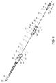
- the safety needle assembly 10 includes a metal needle 12 having an opening 14 extending through a metal shaft 15, which defines an inner surface 16 ( Figure 4 ).
- a tapered sharp tip 17 is positioned at a distal end 18 of the needle 12.
- a needle hub 20 is coupled at or near a proximal end 22 of the needle 12.
- a slot 23 may be formed desirably, but not by way of limitation, at a lower edge 24 of the tapered distal tip 16 of the needle 12.
- a distal end 26 of the needle hub 20 is coupled about a portion of the proximal end 22 of the needle 12.
- the needle hub 20 includes an opening 28 that is continuous with the opening 14 that extends through the hollow shaft 15 of the needle 12 and through the distal tip 16 thereof.
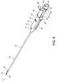
- the needle hub also desirably includes opposing spaced-apart edges 29 at the proximal end 22 thereof.
- the needle hub 20 desirably has a pair of upper apertures or upper recesses 30, one upper recess 30 positioned on each of the relatively flat sides 32, 34 on an outer surface 36 of the hub 20 near a proximal end 40 thereof.
- the apertures or recesses 30, 31 extend from the outer surface 36 to the opening 28 in the needle hub 20. The purpose for the apertures or recesses 30, 31 will be discussed in detail below.
- An inner surface 37 ( Figure 4 ) is provided and is defined by opening 28 formed through the needle hub 20.
- the inner surface 37 is sized to receive a blunted stylus therethrough.
- the hub 20 includes a pair of relatively short sides 38 as well, which are spaced-apart from each other, but are adjacent to the flat sides 32, 36.
- Each short side 38 has a plurality of grooves 39 formed therein to facilitate gripping the hub 20.
- the needle hub 20 also includes, at the proximal end 40, a handle 42 which is desirably positioned to extend away from the proximal end 40.
- the handle 42 may desirably include a handle shaft 44 generally axially aligned with the needle hub 20 and which is desirably integrally formed with the proximal end 40 of the needle hub 20.
- the handle 42 also desirably includes a handle portion 46 which extends at an angle, desirably at about a 90 degree angle, transversely away from the handle shaft 44.
- a pair of wedges 47 are positioned in a spaced-apart orientation on either side of a junction of the shaft 44 and the handle portion 46. The wedges 47 are positioned to function as stops, as will be described in further detail below.
- the needle hub 20 may also include a "C"-clip (not shown) to hold a suture which may be positioned at least partially in the needle 12..
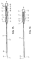
- the blunted safety needle assembly 10 also includes a stylus 50, as illustrated in Figures 5-7 , having a solid or hollow shaft 52 sized to have an outer surface 54 which cooperates to substantially fill a diameter of the inner surface 28 of the needle 12.
- the stylus 50 includes a blunted, non-sharp, distal end 56 and a proximal end 58 which is coupled to a stylus hub 60.
- the distal end 56 is sized and configured to position against and move a fastener positioned near the distal end 18 in the shaft 15 of the needle 12.
- the stylus hub 60 includes, at one end, a cylindrical upper hub 62 which desirably includes a standard luer lock. At an opposite end of the upper hub 62 is a narrower-diameter lower hub 64 which desirably couples about at least a portion of the proximal end 58 of the stylus 50.
- a protruding rim or ridge 63 may extends about a circumference of the junction of the upper hub 62 and the lower hub 64.
- a pair of flanges 68 extend from the lower hub 64 and include free ends 72 which extend away from the upper hub 62 and toward the distal end 56 of the stylus 50, but are in a substantial axial alignment therewith. The flanges 68 flare slightly away from the stylus shaft 52.
- Generally triangularly-shaped (in a side elevational view) clips 74 extend outward on an outer surface 76 of each flange 68 at each free end 72 of the flange 68.
- the flanges 68 and clips 74 thereon provide a retainer. It will be understood that at least a portion of the stylus hub 60, that is, at least the flanges 68, is sized to extend into and contact the inner surface 37 of the needle hub 20 ( Figures 15 and 16 ).
- the stylus 50 may include an opening 78 through hubs 60, 64 and the shaft 52 of the stylus 50.
- a protective sheath 80 may be provided, to isolate the sharp tip 17 of the distal end 18 of the needle 12 and protect the health care provider, until such time as the safety needle assembly 10 is removed from the sheath 80 for use.
- the sheath 80 is sized to hold the needle 12 with the stylus 50 positioned therewith.
- the sheath 80 has an outer surface 82 and an inner surface 84, and is shaped generally like a funnel having a closed end.
- the blunted safety needle assembly 10 is desirably positioned in the sheath 80, with the sharp tip 17 of the distal end 18 of the needle 12 positioned adjacent a closed end 86 of the sheath 80, and the needle hub 20 and stylus hub 50 accessible through an opening 88 in an open end 90 of the sheath 80.
- Slots 92 are positioned adjacent the opening 88 in an opposing, spaced-apart position. Each slot 92 is flanked by a pair of protuberances 94 formed along an edge 96 forming each slot.
- the needle assembly 10 is releasably held in the sheath 80 until a health care provider removes the needle assembly 10 from the sheath 80.
- a health care provider removes the needle assembly 10 from the sheath 80.
- the sheath 80 is formed from a material having resilient qualities, which permits the sheath to operate as shown and/or described herein.
- the stylus 50 is inserted into the hollow needle 12 by introducing the blunted distal end 56 of the stylus 50 into the opening 28 at the proximal end 40 of the needle hub 20.
- the shaft 52 of the stylus 50 is positioned through the opening 28 of the needle hub 20 and through the opening 14 of the shaft 15 of the needle, such that the outer surface 54 of the stylus contacts the inner surface 16 of the needle 12 and a portion of the outer surface 54 of the stylus hub 60 contacts the inner surface 38 of the needle hub 20.
- the stylus hub 60 is desirably aligned with the needle hub 20 during this process, so that the retainer, that is, the flanges 68 of the stylus hub 50 and the clips 74 thereon are oriented to align with and move into the upper apertures or upper recesses 30 in the needle hub 20, thereby holding the stylus 50 to the needle hub 20 and preventing the stylus 50 from falling out of the needle 12 and/or hub 20.
- the rim or ridge 63 on the outer circumference of the upper hub 62 contacts the wedges 47 on the shaft 44 of the handle 42.
- the wedges 47 act as stops, to prevent the movement of the stylus hub 60 and stylus 50 toward the distal end 18 of the needle 12.
- a substance such as, for example only, a radio-opaque substance may be loaded into the shaft 15 of the needle 12 prior to, or after, the introduction of the stylus 50 therein.
- a medical device such as, for example, but not by way of limitation, a fastener 95, such as a T- bar and suture (often referred to as a "T-bar" fastener) often used for a gastropexy procedure, may be positioned in the shaft 15 of the needle 12 prior to, or after, the introduction of the stylus 50 therein. In this circumstance, the T-bar fastener 95 is introduced into the metal shaft 15 of the needle 12 via its distal end 18.
- a suture 96 coupled to the T-bar fastener desirably extends through the slot 23 in the distal tip 17 and end 16 of the needle 12.
- the suture 96 may extend proximally, toward the needle hub 20 and may be releasably held by the hub 20 by passing the suture 96 through a "C"- clip 49 (not shown) on the hub 20.
- the suture 96 desirably, but not by way of limitation, includes a suture holder at an opposite end thereof (not shown).
- the needle assembly 10 is desirably removed from the sheath 80, and a health care provider may introduce the needle 12 of the assembly 10 through a patient's skin and abdominal wall into a patient's stomach (not shown).
- the stylus 50 after the safety needle assembly 10 has been inserted into a target hollow organ or blood vessel, desirably acts to position a substance and/or a device, such as the T-bar fastener 95 and suture 96, in the patient.
- the stylus 50 is desirably activated by a health care provider.
- the provider moves the handle 42 and wedges 47 away from the needle hub 20 by pushing the handle portion 46 downward, thereby positioning the handle 42 in a transverse orientation relative to the needle assembly 10.
- the handle 42 may desirably, but not by way of limitation, be snapped off and removed from the needle hub 20.
- the stylus hub 60 is then pushed so that it moves toward the distal end 18 of the needle 12.
- Moving the stylus 50 within the needle 12 not only moves one or more devices or substances out of the needle 12, but it also acts to position the needle assembly 10 in a blunted position.
- the blunted distal end 56 of the stylus 50 extends a distance beyond the sharp tip17 at the distal end 18 of the needle 12, when the upper hub 62 of the stylus 50 is moved downward in the needle.
- the retainer namely, the clips 76 on the flanges 68, move out of the upper apertures or upper recesses 30 in the needle hub 20 and continue in a movement toward the distal end of the needle hub 20 such that the clips 74 move into the lower apertures or lower recesses 31 of the needle hub 20.
- the retainer via the clips 74 act to lock the stylus 50 into a non-releaseable locked position relative to the needle 12. Therefore, the safety needle assembly 10 is placed in a stable, blunted position which cannot be altered; the clips 74 cannot be removed from the lower apertures 31 once they are positioned in them. In this blunted position, the safety needle assembly 10 is positioned in a permanently blunted position, and the safety needle assembly 10 is not useable again, and must be disposed of.
- the needle 12 is desirably constructed from stainless steel, and may be a 1.22mm (18 gauge) thin wall needle.
- the needle hub 20 is desirably constructed from plastic, and more desirably is a medical grade polycarbonate, medical grade macrolon, or the like.
- the needle tip may desirably be a non-coring needle tip, and may have a double bevel with reverse grind at the tip.
- the stylus 50 is desirably also constructed from stainless steel, and may be a 0.90mm (20 gauge) thin wall hypodermic tube having a blunted, smooth distal end.
- the stylus hub 60 is desirably constructed from plastic, and more desirably is a medical grade polycarbonate, medical grade macrolon, or the like. It will be understood, however, that that any portion of the safety needle assembly 10, including the sheath 80, may be constructed from any material or combination of materials, in any gauge or thickness, with any variations, so long as the safety needle assembly 10 operates as shown and/or described herein.
Landscapes
- Health & Medical Sciences (AREA)
- Life Sciences & Earth Sciences (AREA)
- Surgery (AREA)
- Animal Behavior & Ethology (AREA)
- General Health & Medical Sciences (AREA)
- Engineering & Computer Science (AREA)
- Biomedical Technology (AREA)
- Heart & Thoracic Surgery (AREA)
- Veterinary Medicine (AREA)
- Public Health (AREA)
- Medical Informatics (AREA)
- Molecular Biology (AREA)
- Nuclear Medicine, Radiotherapy & Molecular Imaging (AREA)
- Rheumatology (AREA)
- Pathology (AREA)
- Vascular Medicine (AREA)
- Anesthesiology (AREA)
- Hematology (AREA)
- Infusion, Injection, And Reservoir Apparatuses (AREA)
- Surgical Instruments (AREA)
Claims (12)
- Sicherheitskanülenanordnung (10), welche umfasst:eine Kanüle (12), welche einen Schaft (15) beinhaltet, welcher ein scharfes offenes distales Ende und ein offenes proximales Ende aufweist, wobei das proximale Ende einen Kanülenansatz (20) darauf aufweist, wobei der Kanülenansatz (20) eine Öffnung (28) dahindurch aufweist, welche kontinuierlich ist mit einer Öffnung (14), welche durch den Schaft der Kanüle bereitgestellt wird; und wobei der Kanülenansatz des Weiteren eine Aussparung (30) und eine andere Aussparung (31) darin aufweist; undeinen Stift (50), wobei der Stift einen Schaft (52) aufweist, welcher ein stumpfes distales Ende (56) und ein proximales Ende beinhaltet, welches einen Stiftansatz (60) darauf aufweist, wobei der Stiftansatz (60) eine Halterung (74) beinhaltet;wobei der Stift in einer ersten Position gehalten wird, wenn der Stift in der Kanüle angeordnet ist, wobei das stumpfe distale Ende (46) des Stifts sich um einen Abstand in Richtung des offenen distalen Endes der Kanüle erstreckt aber in dem Schaft der Kanüle durch einen Teil der Halterung gehalten wird, gehalten in der einen Aussparung (30) in dem Kanülenansatz, und wobei der Ansatz des Stifts geschoben wird, um das stumpfe distale Ende des Stifts in den Schaft der Kanüle zu bewegen, wobei sich der Stift (50) in dem Schaft bewegt bis das stumpfe distale Ende (56) sich über das scharfe distale Ende der Kanüle erstreckt und der Teil der Halterung (68, 74) in der anderen Aussparung (31) in dem Kanülenansatz angeordnet ist, wodurch die Sicherheitskanülenanordnung in einen stumpfen Zustand gebracht wird, wobei der Stift eingerichtet ist, sich nicht lösbar mit der Kanüle zu verbinden, um eine nicht bewegbare Position des Stifts in Bezug auf die Kanüle bereitzustellen, um den stumpfen Zustand beizubehalten.
- Sicherheitskanülenanordnung gemäß Anspruch 1,
wobei der Kanülenansatz mindestens einen beweglichen Stopp beinhaltet, welcher darauf angeordnet ist, und wobei der Stiftansatz einen Rand aufweist,
wobei in der ersten Position des Stifts das stumpfe distale Ende des Stifts in dem Schaft der Kanüle durch den Teil der Halterung in der Aussparung in dem Kanülenansatz gehalten wird und durch eine Position des beweglichen Stopps (47) gegen den Rand (63), und
wobei, wenn der bewegliche Stopp (47) weg von dem Rand bewegt wird, das stumpfe distale Ende (46) des Stifts beweglich ist, um sich durch und über das scharfe offene distale Ende der Kanüle zu erstrecken. - Sicherheitskanülenanordnung gemäß Anspruch 2, wobei der Kanülenansatz einen Griff (42) beinhaltet, welcher den Stopp darauf angeordnet aufweist.
- Sicherheitskanülenanordnung gemäß Anspruch 3, wobei der Griff (42) beweglich ist, um den Stopp Weg von dem Stiftansatz zu bewegen, so dass der Stift in Richtung des distalen Endes der Kanüle beweglich ist.
- Sicherheitskanülenanordnung gemäß Anspruch 3, wobei der Griff (42) von dem Kanülenansatz abbricht.
- Sicherheitskanülenanordnung gemäß Anspruch 1, wobei die Halterung (74) einen Clip beinhaltet.
- Sicherheitskanülenanordnung gemäß Anspruch 2, wobei die Halterung einen Clip beinhaltet, und wobei der Clip der Halterung in der einen Aussparung (30) des Kanülenansatzes angeordnet ist, um den Stopp beim Halten des Stifts in einer nicht eingesetzten Position zu unterstützen.
- Sicherheitskanülenanordnung gemäß Anspruch 7, wobei, wenn der bewegliche Stopp (74) von dem Teil des Stifts weg bewegt wird, das stumpfe distale Ende des Stifts beweglich ist, um sich durch und über das scharfe offene distale Ende der Kanüle zu erstrecken, und wobei die Halterung (68, 74) bewegt wird, so dass der Clip der Halterung in einer anderen Aussparung des Kanülenansatzes angeordnet wird, und wobei der Stift sich durch und über das distale Ende der Kanüle in einer eingesetzten Position erstreckt und den Stift in eine nicht bewegliche Position bringt, so dass die Kanülenanordnung in einem sicheren stumpfen Zustand gehalten wird.
- Sicherheitskanülenanordnung gemäß Anspruch 1, wobei der Kanülenansatz einen Griff beinhaltet, welcher einen beweglichen Stopp (47) darauf angeordnet aufweist.
- Sicherheitskanülenanordnung gemäß Anspruch 9, wobei der Stift einen Rand (63) beinhaltet.
- Sicherheitskanülenanordnung gemäß Anspruch 10, wobei, wenn der Stopp auf dem Griff (42) gegen den Rand des Stifts angeordnet wird, der Stift in einer Position gehalten wird, welche eine Bewegung in Richtung des distalen Endes der Kanüle verhindert.
- Sicherheitskanülenanordnung gemäß Anspruch 11, wobei, wenn der Griff (42) bewegt wird, so dass der Stopp weg von dem Rand des Stifts bewegt wird, das stumpfe distale Ende des Stifts beweglich ist, um sich durch und über das scharfe offene distale Ende der Kanüle zu erstrecken, wodurch die Sicherheitskanülenanordnung in einen stumpfen Zustand gebracht wird.
Applications Claiming Priority (2)
| Application Number | Priority Date | Filing Date | Title |
|---|---|---|---|
| US11/848,523 US20090062742A1 (en) | 2007-08-31 | 2007-08-31 | Blunted Safety Needle |
| PCT/IB2008/052421 WO2009027858A1 (en) | 2007-08-31 | 2008-06-19 | Blunted safety needle |
Publications (2)
| Publication Number | Publication Date |
|---|---|
| EP2180835A1 EP2180835A1 (de) | 2010-05-05 |
| EP2180835B1 true EP2180835B1 (de) | 2014-09-24 |
Family
ID=39951508
Family Applications (1)
| Application Number | Title | Priority Date | Filing Date |
|---|---|---|---|
| EP08776430.4A Not-in-force EP2180835B1 (de) | 2007-08-31 | 2008-06-19 | Stumpfe sicherheits-nadel |
Country Status (9)
| Country | Link |
|---|---|
| US (2) | US20090062742A1 (de) |
| EP (1) | EP2180835B1 (de) |
| JP (1) | JP5357157B2 (de) |
| AU (1) | AU2008291775B2 (de) |
| BR (1) | BRPI0815451A2 (de) |
| CA (1) | CA2697641C (de) |
| ES (1) | ES2524785T3 (de) |
| MX (1) | MX2010002232A (de) |
| WO (1) | WO2009027858A1 (de) |
Families Citing this family (7)
| Publication number | Priority date | Publication date | Assignee | Title |
|---|---|---|---|---|
| US8157816B2 (en) | 2007-08-31 | 2012-04-17 | Kimberly-Clark Worldwide, Inc. | Gastropexy kit |
| US9592044B2 (en) | 2011-02-09 | 2017-03-14 | C. R. Bard, Inc. | T-fastener suture delivery system |
| US9833255B2 (en) * | 2013-12-26 | 2017-12-05 | Tenjin, Llc | Percussive surgical devices, systems, and methods of use thereof |
| US10098628B2 (en) | 2014-07-22 | 2018-10-16 | Cook Medical Technologies Llc | Anchor deployment system, device, and method of treatment |
| CN105664352B (zh) * | 2015-11-18 | 2019-11-05 | 珠海和佳医疗设备股份有限公司 | 一种用于介入手术的电磁定位导航粒子植入套针 |
| JP7785538B2 (ja) * | 2018-12-18 | 2025-12-15 | コンメッド コーポレーション | 自穿孔式アンカーインサータ |
| US12433582B2 (en) * | 2020-03-16 | 2025-10-07 | Smith & Nephew, Inc. | Depth penetration limiter for a tissue repair device |
Family Cites Families (108)
| Publication number | Priority date | Publication date | Assignee | Title |
|---|---|---|---|---|
| US2075508A (en) * | 1934-07-18 | 1937-03-30 | Edward W Davidson | Suture retainer |
| US3438373A (en) * | 1966-03-21 | 1969-04-15 | Voys Inc Le | Catheter placement unit with unidirectional locking means to prevent catheter retraction |
| US3664345A (en) * | 1970-07-06 | 1972-05-23 | Clyde Harwell Dabbs | Surgical buttons |
| DE2853289C2 (de) * | 1978-12-09 | 1980-12-18 | B. Braun Melsungen Ag, 3508 Melsungen | Knopf für chirurgische Zwecke |
| US4249535A (en) * | 1979-02-02 | 1981-02-10 | Hargest Thomas S Iii | Gastric feeding device |
| US4393873A (en) * | 1980-03-10 | 1983-07-19 | Nawash Michael S | Gastrostomy and other percutaneous transport tubes |
| US4315513A (en) * | 1980-03-10 | 1982-02-16 | Nawash Michael S | Gastrostomy and other percutaneous transport tubes |
| US4823794A (en) * | 1982-07-12 | 1989-04-25 | Pierce William S | Surgical pledget |
| US4666433A (en) * | 1984-11-05 | 1987-05-19 | Medical Innovations Corporation | Gastrostomy feeding device |
| US4701163A (en) * | 1984-11-05 | 1987-10-20 | Medical Innovations Corporation | Gastrostomy feeding device |
| US4685901A (en) * | 1984-11-05 | 1987-08-11 | Medical Innovations Corporation | Gastro-jejunal feeding device |
| US4798592A (en) * | 1984-11-05 | 1989-01-17 | Medical Innovations Corporation | Gastrostomy feeding device |
| US4669473A (en) * | 1985-09-06 | 1987-06-02 | Acufex Microsurgical, Inc. | Surgical fastener |
| USRE34021E (en) * | 1985-11-18 | 1992-08-04 | Abbott Laboratories | Percutaneous fixation of hollow organs |
| US4705040A (en) * | 1985-11-18 | 1987-11-10 | Medi-Tech, Incorporated | Percutaneous fixation of hollow organs |
| US4627841A (en) | 1986-02-18 | 1986-12-09 | Dorr Robert T | Infusion needle |
| US5123914A (en) * | 1986-05-19 | 1992-06-23 | Cook Incorporated | Visceral anchor for visceral wall mobilization |
| USRE34866E (en) * | 1987-02-17 | 1995-02-21 | Kensey Nash Corporation | Device for sealing percutaneous puncture in a vessel |
| US4852568A (en) * | 1987-02-17 | 1989-08-01 | Kensey Nash Corporation | Method and apparatus for sealing an opening in tissue of a living being |
| US4890612A (en) * | 1987-02-17 | 1990-01-02 | Kensey Nash Corporation | Device for sealing percutaneous puncture in a vessel |
| US5226912A (en) * | 1987-08-26 | 1993-07-13 | United States Surgical Corporation | Combined surgical needle-braided suture device |
| US5222978A (en) | 1987-08-26 | 1993-06-29 | United States Surgical Corporation | Packaged synthetic absorbable surgical elements |
| US5366081A (en) | 1987-08-26 | 1994-11-22 | United States Surgical Corporation | Packaged synthetic absorbable surgical elements |
| US5462162A (en) * | 1987-08-26 | 1995-10-31 | United States Surgical Corporation | Packaged synthetic absorbable surgical elements |
| US6260699B1 (en) * | 1987-08-26 | 2001-07-17 | United States Surgical Corporation | Packaged synthetic absorbable surgical elements |
| US5123912A (en) * | 1987-08-26 | 1992-06-23 | United States Surgical Corporation | Absorbable coating composition, coated sutures and method of preparation |
| US5037429A (en) * | 1987-08-26 | 1991-08-06 | United States Surgical Corporation | Method for improving the storage stability of a polymeric braided suture susceptible to hydrolytic degradation and resulting article |
| US5019093A (en) * | 1989-04-28 | 1991-05-28 | United States Surgical Corporation | Braided suture |
| US5051272A (en) * | 1988-07-19 | 1991-09-24 | United States Surgical Corporation | Method for improving the storage stability of a polymeric article susceptible to hydrolytic degradation and resulting article |
| US5261886A (en) * | 1987-08-26 | 1993-11-16 | United States Surgical Corporation | Cabled core and braided suture made therefrom |
| US5306289A (en) * | 1987-08-26 | 1994-04-26 | United States Surgical Corporation | Braided suture of improved characteristics |
| US5447966A (en) * | 1988-07-19 | 1995-09-05 | United States Surgical Corporation | Treating bioabsorbable surgical articles by coating with glycerine, polalkyleneoxide block copolymer and gelatin |
| US5053047A (en) * | 1989-05-16 | 1991-10-01 | Inbae Yoon | Suture devices particularly useful in endoscopic surgery and methods of suturing |
| US5222976A (en) * | 1989-05-16 | 1993-06-29 | Inbae Yoon | Suture devices particularly useful in endoscopic surgery |
| US5129511A (en) * | 1989-08-01 | 1992-07-14 | United States Surgical Corporation | Package for a combined surgical suture-needle device |
| US5154283A (en) * | 1990-08-13 | 1992-10-13 | United States Surgical Corporation | Molded suture retainer |
| US5425445A (en) * | 1989-08-01 | 1995-06-20 | United States Surgical Corporation | Retainer for a combined surgical suture-needle device |
| US5359831A (en) | 1989-08-01 | 1994-11-01 | United States Surgical Corporation | Molded suture retainer |
| US5246104A (en) * | 1989-08-01 | 1993-09-21 | United States Surgical Corporation | Molded suture retainer |
| US5049138A (en) * | 1989-11-13 | 1991-09-17 | Boston Scientific Corporation | Catheter with dissolvable tip |
| WO1993007813A1 (en) * | 1989-12-04 | 1993-04-29 | Kensey Nash Corporation | Plug device for sealing openings and method of use |
| US5061274A (en) * | 1989-12-04 | 1991-10-29 | Kensey Nash Corporation | Plug device for sealing openings and method of use |
| US5037479A (en) | 1990-04-20 | 1991-08-06 | Rmt, Inc. | Method for reduction of heavy metal leaching from hazardous waste under acidic and nonacidic conditions |
| US5121836A (en) * | 1990-05-25 | 1992-06-16 | United States Surgical Corporation | Retainer for combined surgical suture-needle device |
| US5269809A (en) | 1990-07-02 | 1993-12-14 | American Cyanamid Company | Locking mechanism for use with a slotted suture anchor |
| US5041129A (en) * | 1990-07-02 | 1991-08-20 | Acufex Microsurgical, Inc. | Slotted suture anchor and method of anchoring a suture |
| US5261210A (en) * | 1990-08-13 | 1993-11-16 | United States Surgical Corporation | Molded suture retainer |
| US5074846A (en) | 1990-09-13 | 1991-12-24 | Abbott Laboratories | Stoma creator gastrostomy device and method for placement of a feeding tube |
| US5167627A (en) | 1990-09-13 | 1992-12-01 | Abbott Laboratories | Stoma creator gastrostomy device and method for placement of a feeding tube |
| US5112310A (en) * | 1991-02-06 | 1992-05-12 | Grobe James L | Apparatus and methods for percutaneous endoscopic gastrostomy |
| US5186985A (en) * | 1991-04-04 | 1993-02-16 | E. I. Du Pont De Nemours And Company | Liquid crystal displays of high tilt bias angles |
| US5258015A (en) * | 1991-05-03 | 1993-11-02 | American Cyanamid Company | Locking filament caps |
| US5316013A (en) * | 1991-08-26 | 1994-05-31 | Hart Enterprises, Inc. | Oriented biopsy needle assembly |
| DE69210757T2 (de) * | 1991-09-27 | 1996-10-02 | Dlp Inc | Biopsienadel mit Abstandshalter |
| US5312345A (en) * | 1992-03-11 | 1994-05-17 | Cole Richard D | Anti-needle stick protective inner blunt tubular stylet for intravenous therapy |
| US5318543A (en) * | 1992-10-08 | 1994-06-07 | Abbott Laboratories | Laparoscopic jejunostomy instrumentation kit |
| US5273529A (en) | 1992-12-04 | 1993-12-28 | Olajire Idowu | Gastrostomy tube with expandable insertion tip |
| US5307924A (en) * | 1993-03-26 | 1994-05-03 | Abbott Laboratories | Packaging for T-shaped tension devices |
| US5312435A (en) * | 1993-05-17 | 1994-05-17 | Kensey Nash Corporation | Fail predictable, reinforced anchor for hemostatic puncture closure |
| DE4325766C1 (de) | 1993-07-31 | 1995-05-11 | Deknatel Med Prod | Verfahren zur Behandlung von synthetischem resorbierbaren Nahtmaterial |
| US5451212A (en) * | 1994-01-21 | 1995-09-19 | Corpak, Inc. | Bumper retention device |
| US5391159A (en) * | 1994-02-04 | 1995-02-21 | Hirsch; William H. | Gastrostomy tube with improved internal retaining member |
| US5531759A (en) * | 1994-04-29 | 1996-07-02 | Kensey Nash Corporation | System for closing a percutaneous puncture formed by a trocar to prevent tissue at the puncture from herniating |
| US5545178A (en) * | 1994-04-29 | 1996-08-13 | Kensey Nash Corporation | System for closing a percutaneous puncture formed by a trocar to prevent tissue at the puncture from herniating |
| US5531699A (en) * | 1994-09-19 | 1996-07-02 | Abbott Laboratories | Spring-loaded reciprocable stylet holder |
| JP3580903B2 (ja) | 1994-09-26 | 2004-10-27 | オリンパス株式会社 | 吊り上げ具 |
| US5851195A (en) * | 1995-05-17 | 1998-12-22 | Gill; Inderbir S. | Direct percutaneous endoscopic jejunostomy method and apparatus |
| US5626614A (en) | 1995-12-22 | 1997-05-06 | Applied Medical Resources Corporation | T-anchor suturing device and method for using same |
| US5743882A (en) * | 1996-03-08 | 1998-04-28 | Luther Medical Products, Inc. | Needle blunting assembly for use with intravascular introducers |
| US5817060A (en) * | 1996-03-08 | 1998-10-06 | Luther Medical Products, Inc. | Unidirectional blunting apparatus for hypodermic needles |
| SE513823C2 (sv) * | 1996-05-31 | 2000-11-13 | Wiklund Ernst S G F | Spetsskydd för punktionsnålar |
| US5951520A (en) * | 1996-12-19 | 1999-09-14 | Bio-Plexus, Inc. | Self-blunting needle medical devices and methods of manufacture thereof |
| ATE286754T1 (de) * | 1997-03-26 | 2005-01-15 | Bio Plexus Inc | Vorrichtung zum überleiten einer parenteralen flüssigkeit |
| US6063106A (en) * | 1997-09-19 | 2000-05-16 | Gibson; William Frits Stewart | Surgical spacer |
| US6077250A (en) * | 1997-10-01 | 2000-06-20 | Boston Scientific Corporation | Apparatus and method for percutaneously placing gastrostomy tubes |
| US6186985B1 (en) | 1997-10-03 | 2001-02-13 | Boston Scientific Corporation | Gastro-intestinal tube with dissolvable support bolster |
| US6030364A (en) * | 1997-10-03 | 2000-02-29 | Boston Scientific Corporation | Apparatus and method for percutaneous placement of gastro-intestinal tubes |
| US6626919B1 (en) * | 1997-12-29 | 2003-09-30 | Lee L. Swanstrom | Method and apparatus for attaching or locking an implant to an anatomic vessel or hollow organ wall |
| US6332877B1 (en) | 1998-05-12 | 2001-12-25 | Novartis Ag | Ostomy tube placement tip |
| US6039714A (en) * | 1998-05-12 | 2000-03-21 | Novartis Nutrition Ag | Collapsible retention bolster for gastrostomy and other ostomy tubes |
| US6669707B1 (en) | 1998-07-21 | 2003-12-30 | Lee L. Swanstrom | Method and apparatus for attaching or locking an implant to an anatomic vessel or hollow organ wall |
| US6270480B1 (en) * | 1998-10-05 | 2001-08-07 | Cancer Technologies, Inc. | Catheter apparatus and method |
| US6544239B2 (en) * | 1998-10-16 | 2003-04-08 | Bio-Plexus Delaware, Inc. | Releasable locking needle assembly with optional release accessory therefor |
| US6110183A (en) * | 1998-12-22 | 2000-08-29 | Cook Incorporated | Suture anchor device |
| ATE324072T1 (de) * | 1998-12-30 | 2006-05-15 | Ethicon Inc | Fadensicherungsgerät |
| US6315789B1 (en) | 1999-02-08 | 2001-11-13 | Andrew H. Cragg | Medical device anchoring system and method |
| US6450937B1 (en) * | 1999-12-17 | 2002-09-17 | C. R. Bard, Inc. | Needle for implanting brachytherapy seeds |
| US6475189B1 (en) | 1999-12-21 | 2002-11-05 | Ethicon, Inc. | Apparatus and method for a self-blunting safety catheter |
| US6328720B1 (en) * | 2000-02-18 | 2001-12-11 | Zevex, Inc. | Low-profile enterostomy device |
| DE10027186C2 (de) | 2000-05-31 | 2002-06-27 | Aesculap Ag & Co Kg | Vorrichtung zum Verschliessen einer Öffnung in einer Gewebeschicht |
| US6582443B2 (en) * | 2000-12-27 | 2003-06-24 | Ams Research Corporation | Apparatus and methods for enhancing the functional longevity and for facilitating the implantation of medical devices |
| US6811545B2 (en) * | 2001-01-31 | 2004-11-02 | Vincent L. Vaillancourt | Safety needle |
| US6997931B2 (en) * | 2001-02-02 | 2006-02-14 | Lsi Solutions, Inc. | System for endoscopic suturing |
| US8313496B2 (en) * | 2001-02-02 | 2012-11-20 | Lsi Solutions, Inc. | System for endoscopic suturing |
| WO2002066108A1 (en) | 2001-02-15 | 2002-08-29 | Sherwood Services, Ag | Securing device for a low profile gastrostomy tube |
| US6673058B2 (en) * | 2001-06-20 | 2004-01-06 | Scimed Life Systems, Inc. | Temporary dilating tip for gastro-intestinal tubes |
| US7001361B2 (en) * | 2001-08-24 | 2006-02-21 | Medical Engenuity Llc | Blunting device for a hollow medical needle |
| US6896665B2 (en) * | 2001-12-10 | 2005-05-24 | Applied Medical Research | Gastrostomy device package and method of assembly |
| US6699263B2 (en) * | 2002-04-05 | 2004-03-02 | Cook Incorporated | Sliding suture anchor |
| US6837872B2 (en) * | 2002-05-02 | 2005-01-04 | Becton, Dickinson And Company | Needle holder for use with safety needle assembly |
| US6773440B2 (en) * | 2002-07-02 | 2004-08-10 | Satiety, Inc. | Method and device for use in tissue approximation and fixation |
| US6966916B2 (en) | 2002-09-26 | 2005-11-22 | Kumar Sarbjeet S | Device and method for surgical repair of abdominal wall hernias |
| US7300451B2 (en) * | 2003-12-22 | 2007-11-27 | Ethicon, Inc. | Suture anchoring device |
| US7686830B2 (en) * | 2003-12-22 | 2010-03-30 | Ethicon, Inc. | Suture anchoring device |
| US7066944B2 (en) * | 2004-03-11 | 2006-06-27 | Laufer Michael D | Surgical fastening system |
| JP4669315B2 (ja) | 2005-04-21 | 2011-04-13 | 日本シャーウッド株式会社 | 臓器固定具および臓器固定具セット |
| US7520869B2 (en) * | 2004-10-29 | 2009-04-21 | Merit Medical Systems, Inc. | Self-suturing anchor device for a catheter |
| EP1749481A1 (de) | 2005-08-02 | 2007-02-07 | Marco Gandini | Nähvorrichtung |
-
2007
- 2007-08-31 US US11/848,523 patent/US20090062742A1/en not_active Abandoned
-
2008
- 2008-06-19 ES ES08776430.4T patent/ES2524785T3/es active Active
- 2008-06-19 CA CA2697641A patent/CA2697641C/en active Active
- 2008-06-19 BR BRPI0815451-1A2A patent/BRPI0815451A2/pt not_active Application Discontinuation
- 2008-06-19 WO PCT/IB2008/052421 patent/WO2009027858A1/en not_active Ceased
- 2008-06-19 EP EP08776430.4A patent/EP2180835B1/de not_active Not-in-force
- 2008-06-19 MX MX2010002232A patent/MX2010002232A/es active IP Right Grant
- 2008-06-19 JP JP2010522476A patent/JP5357157B2/ja not_active Expired - Fee Related
- 2008-06-19 AU AU2008291775A patent/AU2008291775B2/en not_active Ceased
-
2016
- 2016-01-19 US US15/000,625 patent/US9968350B2/en active Active
Also Published As
| Publication number | Publication date |
|---|---|
| CA2697641C (en) | 2015-09-08 |
| BRPI0815451A2 (pt) | 2015-02-18 |
| ES2524785T3 (es) | 2014-12-12 |
| JP2010537690A (ja) | 2010-12-09 |
| WO2009027858A1 (en) | 2009-03-05 |
| JP5357157B2 (ja) | 2013-12-04 |
| US20090062742A1 (en) | 2009-03-05 |
| AU2008291775B2 (en) | 2013-05-02 |
| US20160128686A1 (en) | 2016-05-12 |
| MX2010002232A (es) | 2010-03-25 |
| EP2180835A1 (de) | 2010-05-05 |
| AU2008291775A1 (en) | 2009-03-05 |
| US9968350B2 (en) | 2018-05-15 |
| CA2697641A1 (en) | 2009-03-05 |
Similar Documents
| Publication | Publication Date | Title |
|---|---|---|
| US9968350B2 (en) | Blunted safety needle | |
| EP2194883B1 (de) | Gastropexie-kit | |
| CA2037052C (en) | A method and system for inserting spinal catheters | |
| EP1453561B1 (de) | Vorrichtung zur entfernung eines nadel-verschlusssystems | |
| US8313469B2 (en) | I.V. catheter assembly and needle safety device | |
| US8834422B2 (en) | Vascular access assembly and safety device | |
| WO2018089385A1 (en) | Needle cover apparatus | |
| US5817060A (en) | Unidirectional blunting apparatus for hypodermic needles | |
| CA1326194C (en) | Method and system for inserting spinal catheters |
Legal Events
| Date | Code | Title | Description |
|---|---|---|---|
| PUAI | Public reference made under article 153(3) epc to a published international application that has entered the european phase |
Free format text: ORIGINAL CODE: 0009012 |
|
| 17P | Request for examination filed |
Effective date: 20100217 |
|
| AK | Designated contracting states |
Kind code of ref document: A1 Designated state(s): AT BE BG CH CY CZ DE DK EE ES FI FR GB GR HR HU IE IS IT LI LT LU LV MC MT NL NO PL PT RO SE SI SK TR |
|
| AX | Request for extension of the european patent |
Extension state: AL BA MK RS |
|
| DAX | Request for extension of the european patent (deleted) | ||
| 17Q | First examination report despatched |
Effective date: 20130603 |
|
| GRAP | Despatch of communication of intention to grant a patent |
Free format text: ORIGINAL CODE: EPIDOSNIGR1 |
|
| INTG | Intention to grant announced |
Effective date: 20140422 |
|
| GRAS | Grant fee paid |
Free format text: ORIGINAL CODE: EPIDOSNIGR3 |
|
| GRAA | (expected) grant |
Free format text: ORIGINAL CODE: 0009210 |
|
| AK | Designated contracting states |
Kind code of ref document: B1 Designated state(s): AT BE BG CH CY CZ DE DK EE ES FI FR GB GR HR HU IE IS IT LI LT LU LV MC MT NL NO PL PT RO SE SI SK TR |
|
| REG | Reference to a national code |
Ref country code: GB Ref legal event code: FG4D |
|
| REG | Reference to a national code |
Ref country code: CH Ref legal event code: EP |
|
| REG | Reference to a national code |
Ref country code: AT Ref legal event code: REF Ref document number: 688232 Country of ref document: AT Kind code of ref document: T Effective date: 20141015 |
|
| REG | Reference to a national code |
Ref country code: IE Ref legal event code: FG4D |
|
| REG | Reference to a national code |
Ref country code: DE Ref legal event code: R096 Ref document number: 602008034577 Country of ref document: DE Effective date: 20141106 |
|
| REG | Reference to a national code |
Ref country code: ES Ref legal event code: FG2A Ref document number: 2524785 Country of ref document: ES Kind code of ref document: T3 Effective date: 20141212 |
|
| REG | Reference to a national code |
Ref country code: NL Ref legal event code: T3 |
|
| PG25 | Lapsed in a contracting state [announced via postgrant information from national office to epo] |
Ref country code: LT Free format text: LAPSE BECAUSE OF FAILURE TO SUBMIT A TRANSLATION OF THE DESCRIPTION OR TO PAY THE FEE WITHIN THE PRESCRIBED TIME-LIMIT Effective date: 20140924 Ref country code: NO Free format text: LAPSE BECAUSE OF FAILURE TO SUBMIT A TRANSLATION OF THE DESCRIPTION OR TO PAY THE FEE WITHIN THE PRESCRIBED TIME-LIMIT Effective date: 20141224 Ref country code: GR Free format text: LAPSE BECAUSE OF FAILURE TO SUBMIT A TRANSLATION OF THE DESCRIPTION OR TO PAY THE FEE WITHIN THE PRESCRIBED TIME-LIMIT Effective date: 20141225 Ref country code: FI Free format text: LAPSE BECAUSE OF FAILURE TO SUBMIT A TRANSLATION OF THE DESCRIPTION OR TO PAY THE FEE WITHIN THE PRESCRIBED TIME-LIMIT Effective date: 20140924 Ref country code: SE Free format text: LAPSE BECAUSE OF FAILURE TO SUBMIT A TRANSLATION OF THE DESCRIPTION OR TO PAY THE FEE WITHIN THE PRESCRIBED TIME-LIMIT Effective date: 20140924 |
|
| REG | Reference to a national code |
Ref country code: DE Ref legal event code: R082 Ref document number: 602008034577 Country of ref document: DE Representative=s name: ZIMMERMANN & PARTNER, DE |
|
| REG | Reference to a national code |
Ref country code: LT Ref legal event code: MG4D |
|
| PG25 | Lapsed in a contracting state [announced via postgrant information from national office to epo] |
Ref country code: LV Free format text: LAPSE BECAUSE OF FAILURE TO SUBMIT A TRANSLATION OF THE DESCRIPTION OR TO PAY THE FEE WITHIN THE PRESCRIBED TIME-LIMIT Effective date: 20140924 Ref country code: CY Free format text: LAPSE BECAUSE OF FAILURE TO SUBMIT A TRANSLATION OF THE DESCRIPTION OR TO PAY THE FEE WITHIN THE PRESCRIBED TIME-LIMIT Effective date: 20140924 Ref country code: HR Free format text: LAPSE BECAUSE OF FAILURE TO SUBMIT A TRANSLATION OF THE DESCRIPTION OR TO PAY THE FEE WITHIN THE PRESCRIBED TIME-LIMIT Effective date: 20140924 |
|
| REG | Reference to a national code |
Ref country code: DE Ref legal event code: R081 Ref document number: 602008034577 Country of ref document: DE Owner name: AVENT, INC., ALPHARETTA, US Free format text: FORMER OWNER: KIMBERLY-CLARK WORLDWIDE, INC., NEENAH, WIS., US Effective date: 20150130 Ref country code: DE Ref legal event code: R082 Ref document number: 602008034577 Country of ref document: DE Representative=s name: ZIMMERMANN & PARTNER, DE Effective date: 20150130 Ref country code: DE Ref legal event code: R082 Ref document number: 602008034577 Country of ref document: DE Representative=s name: ZIMMERMANN & PARTNER PATENTANWAELTE MBB, DE Effective date: 20150130 |
|
| REG | Reference to a national code |
Ref country code: AT Ref legal event code: MK05 Ref document number: 688232 Country of ref document: AT Kind code of ref document: T Effective date: 20140924 |
|
| REG | Reference to a national code |
Ref country code: GB Ref legal event code: 732E Free format text: REGISTERED BETWEEN 20150402 AND 20150408 |
|
| PG25 | Lapsed in a contracting state [announced via postgrant information from national office to epo] |
Ref country code: RO Free format text: LAPSE BECAUSE OF FAILURE TO SUBMIT A TRANSLATION OF THE DESCRIPTION OR TO PAY THE FEE WITHIN THE PRESCRIBED TIME-LIMIT Effective date: 20140924 Ref country code: SK Free format text: LAPSE BECAUSE OF FAILURE TO SUBMIT A TRANSLATION OF THE DESCRIPTION OR TO PAY THE FEE WITHIN THE PRESCRIBED TIME-LIMIT Effective date: 20140924 Ref country code: PT Free format text: LAPSE BECAUSE OF FAILURE TO SUBMIT A TRANSLATION OF THE DESCRIPTION OR TO PAY THE FEE WITHIN THE PRESCRIBED TIME-LIMIT Effective date: 20150126 Ref country code: CZ Free format text: LAPSE BECAUSE OF FAILURE TO SUBMIT A TRANSLATION OF THE DESCRIPTION OR TO PAY THE FEE WITHIN THE PRESCRIBED TIME-LIMIT Effective date: 20140924 Ref country code: IS Free format text: LAPSE BECAUSE OF FAILURE TO SUBMIT A TRANSLATION OF THE DESCRIPTION OR TO PAY THE FEE WITHIN THE PRESCRIBED TIME-LIMIT Effective date: 20150124 Ref country code: EE Free format text: LAPSE BECAUSE OF FAILURE TO SUBMIT A TRANSLATION OF THE DESCRIPTION OR TO PAY THE FEE WITHIN THE PRESCRIBED TIME-LIMIT Effective date: 20140924 |
|
| REG | Reference to a national code |
Ref country code: FR Ref legal event code: PLFP Year of fee payment: 8 |
|
| PG25 | Lapsed in a contracting state [announced via postgrant information from national office to epo] |
Ref country code: AT Free format text: LAPSE BECAUSE OF FAILURE TO SUBMIT A TRANSLATION OF THE DESCRIPTION OR TO PAY THE FEE WITHIN THE PRESCRIBED TIME-LIMIT Effective date: 20140924 Ref country code: PL Free format text: LAPSE BECAUSE OF FAILURE TO SUBMIT A TRANSLATION OF THE DESCRIPTION OR TO PAY THE FEE WITHIN THE PRESCRIBED TIME-LIMIT Effective date: 20140924 |
|
| REG | Reference to a national code |
Ref country code: DE Ref legal event code: R097 Ref document number: 602008034577 Country of ref document: DE |
|
| PG25 | Lapsed in a contracting state [announced via postgrant information from national office to epo] |
Ref country code: DK Free format text: LAPSE BECAUSE OF FAILURE TO SUBMIT A TRANSLATION OF THE DESCRIPTION OR TO PAY THE FEE WITHIN THE PRESCRIBED TIME-LIMIT Effective date: 20140924 |
|
| PLBE | No opposition filed within time limit |
Free format text: ORIGINAL CODE: 0009261 |
|
| STAA | Information on the status of an ep patent application or granted ep patent |
Free format text: STATUS: NO OPPOSITION FILED WITHIN TIME LIMIT |
|
| 26N | No opposition filed |
Effective date: 20150625 |
|
| PG25 | Lapsed in a contracting state [announced via postgrant information from national office to epo] |
Ref country code: MC Free format text: LAPSE BECAUSE OF FAILURE TO SUBMIT A TRANSLATION OF THE DESCRIPTION OR TO PAY THE FEE WITHIN THE PRESCRIBED TIME-LIMIT Effective date: 20140924 Ref country code: IT Free format text: LAPSE BECAUSE OF NON-PAYMENT OF DUE FEES Effective date: 20150619 |
|
| REG | Reference to a national code |
Ref country code: CH Ref legal event code: PL |
|
| PG25 | Lapsed in a contracting state [announced via postgrant information from national office to epo] |
Ref country code: SI Free format text: LAPSE BECAUSE OF FAILURE TO SUBMIT A TRANSLATION OF THE DESCRIPTION OR TO PAY THE FEE WITHIN THE PRESCRIBED TIME-LIMIT Effective date: 20140924 Ref country code: LU Free format text: LAPSE BECAUSE OF FAILURE TO SUBMIT A TRANSLATION OF THE DESCRIPTION OR TO PAY THE FEE WITHIN THE PRESCRIBED TIME-LIMIT Effective date: 20150619 |
|
| REG | Reference to a national code |
Ref country code: IE Ref legal event code: MM4A |
|
| REG | Reference to a national code |
Ref country code: ES Ref legal event code: PC2A Owner name: AVENT, INC. Effective date: 20160421 |
|
| PG25 | Lapsed in a contracting state [announced via postgrant information from national office to epo] |
Ref country code: CH Free format text: LAPSE BECAUSE OF NON-PAYMENT OF DUE FEES Effective date: 20150630 Ref country code: IE Free format text: LAPSE BECAUSE OF NON-PAYMENT OF DUE FEES Effective date: 20150619 Ref country code: LI Free format text: LAPSE BECAUSE OF NON-PAYMENT OF DUE FEES Effective date: 20150630 |
|
| PGRI | Patent reinstated in contracting state [announced from national office to epo] |
Ref country code: IT Effective date: 20160412 |
|
| REG | Reference to a national code |
Ref country code: FR Ref legal event code: TP Owner name: AVENT, INC., US Effective date: 20160420 |
|
| REG | Reference to a national code |
Ref country code: FR Ref legal event code: PLFP Year of fee payment: 9 |
|
| REG | Reference to a national code |
Ref country code: NL Ref legal event code: PD Owner name: AVENT INC; US Free format text: DETAILS ASSIGNMENT: VERANDERING VAN EIGENAAR(S), OVERDRACHT; FORMER OWNER NAME: KIMBERLY-CLARK WORLDWIDE, INC. Effective date: 20160401 |
|
| PG25 | Lapsed in a contracting state [announced via postgrant information from national office to epo] |
Ref country code: MT Free format text: LAPSE BECAUSE OF FAILURE TO SUBMIT A TRANSLATION OF THE DESCRIPTION OR TO PAY THE FEE WITHIN THE PRESCRIBED TIME-LIMIT Effective date: 20140924 |
|
| REG | Reference to a national code |
Ref country code: FR Ref legal event code: PLFP Year of fee payment: 10 |
|
| PG25 | Lapsed in a contracting state [announced via postgrant information from national office to epo] |
Ref country code: BG Free format text: LAPSE BECAUSE OF FAILURE TO SUBMIT A TRANSLATION OF THE DESCRIPTION OR TO PAY THE FEE WITHIN THE PRESCRIBED TIME-LIMIT Effective date: 20140924 Ref country code: HU Free format text: LAPSE BECAUSE OF FAILURE TO SUBMIT A TRANSLATION OF THE DESCRIPTION OR TO PAY THE FEE WITHIN THE PRESCRIBED TIME-LIMIT; INVALID AB INITIO Effective date: 20080619 |
|
| PG25 | Lapsed in a contracting state [announced via postgrant information from national office to epo] |
Ref country code: TR Free format text: LAPSE BECAUSE OF FAILURE TO SUBMIT A TRANSLATION OF THE DESCRIPTION OR TO PAY THE FEE WITHIN THE PRESCRIBED TIME-LIMIT Effective date: 20140924 |
|
| PG25 | Lapsed in a contracting state [announced via postgrant information from national office to epo] |
Ref country code: BE Free format text: LAPSE BECAUSE OF FAILURE TO SUBMIT A TRANSLATION OF THE DESCRIPTION OR TO PAY THE FEE WITHIN THE PRESCRIBED TIME-LIMIT Effective date: 20140924 |
|
| REG | Reference to a national code |
Ref country code: FR Ref legal event code: PLFP Year of fee payment: 11 |
|
| PGFP | Annual fee paid to national office [announced via postgrant information from national office to epo] |
Ref country code: IS Payment date: 20180518 Year of fee payment: 11 Ref country code: NL Payment date: 20180528 Year of fee payment: 11 |
|
| PGFP | Annual fee paid to national office [announced via postgrant information from national office to epo] |
Ref country code: ES Payment date: 20180702 Year of fee payment: 11 |
|
| REG | Reference to a national code |
Ref country code: NL Ref legal event code: MM Effective date: 20190701 |
|
| PG25 | Lapsed in a contracting state [announced via postgrant information from national office to epo] |
Ref country code: NL Free format text: LAPSE BECAUSE OF NON-PAYMENT OF DUE FEES Effective date: 20190701 Ref country code: IT Free format text: LAPSE BECAUSE OF NON-PAYMENT OF DUE FEES Effective date: 20190619 |
|
| REG | Reference to a national code |
Ref country code: ES Ref legal event code: FD2A Effective date: 20201029 |
|
| PG25 | Lapsed in a contracting state [announced via postgrant information from national office to epo] |
Ref country code: ES Free format text: LAPSE BECAUSE OF NON-PAYMENT OF DUE FEES Effective date: 20190620 |
|
| PGFP | Annual fee paid to national office [announced via postgrant information from national office to epo] |
Ref country code: GB Payment date: 20220428 Year of fee payment: 15 Ref country code: FR Payment date: 20220408 Year of fee payment: 15 Ref country code: DE Payment date: 20220427 Year of fee payment: 15 |
|
| P01 | Opt-out of the competence of the unified patent court (upc) registered |
Effective date: 20230518 |
|
| REG | Reference to a national code |
Ref country code: DE Ref legal event code: R119 Ref document number: 602008034577 Country of ref document: DE |
|
| GBPC | Gb: european patent ceased through non-payment of renewal fee |
Effective date: 20230619 |
|
| PG25 | Lapsed in a contracting state [announced via postgrant information from national office to epo] |
Ref country code: DE Free format text: LAPSE BECAUSE OF NON-PAYMENT OF DUE FEES Effective date: 20240103 Ref country code: GB Free format text: LAPSE BECAUSE OF NON-PAYMENT OF DUE FEES Effective date: 20230619 |
|
| PG25 | Lapsed in a contracting state [announced via postgrant information from national office to epo] |
Ref country code: FR Free format text: LAPSE BECAUSE OF NON-PAYMENT OF DUE FEES Effective date: 20230630 |