EP2180951B1 - Durchflusssensor und herstellungsverfahren dafür - Google Patents
Durchflusssensor und herstellungsverfahren dafür Download PDFInfo
- Publication number
- EP2180951B1 EP2180951B1 EP08787351.9A EP08787351A EP2180951B1 EP 2180951 B1 EP2180951 B1 EP 2180951B1 EP 08787351 A EP08787351 A EP 08787351A EP 2180951 B1 EP2180951 B1 EP 2180951B1
- Authority
- EP
- European Patent Office
- Prior art keywords
- cover plate
- flow channel
- flow
- channel
- base member
- Prior art date
- Legal status (The legal status is an assumption and is not a legal conclusion. Google has not performed a legal analysis and makes no representation as to the accuracy of the status listed.)
- Active
Links
Images





Classifications
-
- G—PHYSICS
- G01—MEASURING; TESTING
- G01F—MEASURING VOLUME, VOLUME FLOW, MASS FLOW OR LIQUID LEVEL; METERING BY VOLUME
- G01F1/00—Measuring the volume flow or mass flow of fluid or fluent solid material wherein the fluid passes through a meter in a continuous flow
- G01F1/68—Measuring the volume flow or mass flow of fluid or fluent solid material wherein the fluid passes through a meter in a continuous flow by using thermal effects
- G01F1/684—Structural arrangements; Mounting of elements, e.g. in relation to fluid flow
- G01F1/6845—Micromachined devices
-
- G—PHYSICS
- G01—MEASURING; TESTING
- G01F—MEASURING VOLUME, VOLUME FLOW, MASS FLOW OR LIQUID LEVEL; METERING BY VOLUME
- G01F15/00—Details of, or accessories for, apparatus of groups G01F1/00 - G01F13/00 insofar as such details or appliances are not adapted to particular types of such apparatus
- G01F15/18—Supports or connecting means for meters
-
- B—PERFORMING OPERATIONS; TRANSPORTING
- B01—PHYSICAL OR CHEMICAL PROCESSES OR APPARATUS IN GENERAL
- B01L—CHEMICAL OR PHYSICAL LABORATORY APPARATUS FOR GENERAL USE
- B01L3/00—Containers or dishes for laboratory use, e.g. laboratory glassware; Droppers
- B01L3/50—Containers for the purpose of retaining a material to be analysed, e.g. test tubes
- B01L3/502—Containers for the purpose of retaining a material to be analysed, e.g. test tubes with fluid transport, e.g. in multi-compartment structures
- B01L3/5027—Containers for the purpose of retaining a material to be analysed, e.g. test tubes with fluid transport, e.g. in multi-compartment structures by integrated microfluidic structures, i.e. dimensions of channels and chambers are such that surface tension forces are important, e.g. lab-on-a-chip
- B01L3/502707—Containers for the purpose of retaining a material to be analysed, e.g. test tubes with fluid transport, e.g. in multi-compartment structures by integrated microfluidic structures, i.e. dimensions of channels and chambers are such that surface tension forces are important, e.g. lab-on-a-chip characterised by the manufacture of the container or its components
-
- Y—GENERAL TAGGING OF NEW TECHNOLOGICAL DEVELOPMENTS; GENERAL TAGGING OF CROSS-SECTIONAL TECHNOLOGIES SPANNING OVER SEVERAL SECTIONS OF THE IPC; TECHNICAL SUBJECTS COVERED BY FORMER USPC CROSS-REFERENCE ART COLLECTIONS [XRACs] AND DIGESTS
- Y10—TECHNICAL SUBJECTS COVERED BY FORMER USPC
- Y10T—TECHNICAL SUBJECTS COVERED BY FORMER US CLASSIFICATION
- Y10T29/00—Metal working
- Y10T29/49—Method of mechanical manufacture
- Y10T29/49826—Assembling or joining
Definitions
- the present invention relates to a flow sensor and a method for the production of the flow sensor, in particular a flow sensor for measuring the flow of fluids, in particular for measuring the flow of air and other gases. More particularly, the present invention relates to a flow sensor and a method of manufacturing the flow sensor comprising a base body having a flow channel, a flow sensor element adjacent to the flow channel, and a cover plate covering the flow channel disposed on the base.
- EP 1 182 432 describes a two-part housing flow sensor for the flow measurement of fluids, which comprises a arranged between the housing parts semiconductor chip with sensor array.
- the semiconductor chip is located on a measuring channel formed as a groove in one of the housing parts.
- a sealing ring is also arranged between the housing parts.
- a conductor foil is guided outward from the semiconductor chip between the sealing ring and the other of the housing parts.
- Connections from the measuring channel to the gap between the housing parts and through glue deposits in the measuring channel can cause accumulations of soiling, which can cause a turbulent flow through the measuring channel and thus impair the quality of the flow measurement.
- a sensor comprising microfluidic channels is known in which lateral sealing lips are made of elastic material. By arranging different microfluidic channels side by side, a high aspect ratio can be achieved.
- a disposable cassette for use in analysis technology which consists of a first part with channel structures formed therein and a second part sealingly covering same.
- the first part has rigid and flexible regions and is made in one piece by the two-component injection molding process.
- Actuator elements for controlling a fluid flow act on the flexible regions.
- WO 02/12734 A discloses a flow sensor according to the preamble of claim 1.
- the flow sensor comprises a base body with a flow channel, a flow sensor element adjoining the flow channel and a cover plate arranged on the base body and covering the flow channel.
- the flow channel is formed by a sealing lip, which circumscribes the flow channel on an upper side of the base body opposite the cover plate and is pressed sealingly against the cover plate.
- a sealing lip which circumscribes the flow channel on an upper side of the base body opposite the cover plate and is pressed sealingly against the cover plate.
- the sealing lip also seals the flow channel with respect to the cover plate, so that a flow channel with a flat channel bed is formed by the sealing lip and the cover plate on the top of the body having smooth boundary surfaces and a constant cross section, and the deposition and accumulation of dirt particles possibly avoids and possibly prevents penetration of adhesives when mounting the cover plate on the body in the flow channel. This can prevent unwanted turbulence in the flow channel and a laminar flow through the flow channel can be effected.
- the base body is formed from a first and a second region, each consisting of a different material and are interconnected, wherein the flow channel is formed in the first region, which is compared to the second region of a much more elastic material.
- the two regions are preferably produced in the two-component injection molding process and are preferably in the composite material.
- the sealing lip is formed elastically and in one piece with the channel bed.
- the second region is designed such that a surface plane defined with respect to a channel bed of the flow channel exists, which lies between the plane of the channel bed and the sealing lips protruding beyond it, so that a predetermined sealing force exists at all points of the sealing surface between cover plate and sealing lip. which is achievable in a simple well-defined way.
- the base body in the second, non-elastic region formed connections for a flow medium, preferably air or other gases.
- the ports are each connected via a bore to one of the ends of the flow channel.
- the flow sensor element is embedded in the cover plate above the flow channel and forms with the cover plate a substantially planar ceiling of the flow channel.
- the sealing lip is at the cover plate remote from the top of the base body opposite end rejuvenated. That is, the sealing lip is tapered at the end, which is pressed resiliently when attaching the cover plate on the base body to the cover plate.
- the tapering of the sealing lip compensates for the elastic deformation of the sealing lip caused by the pressing of the cover plate such that when the cover plate is fastened, a substantially rectangular cross-section of the flow channel is formed, which has no significant deformation on the side walls of the flow channel formed by the sealing lip.
- the flow channel is formed on a channel bed on the upper side of the main body so that the flow channel is laterally separated in cross section by the upstanding from the channel bed sealing lips of a flow channel surrounding outer channel.
- the sealing lip is arranged on a channel bed, that the channel bed is delimited by the sealing lip in three areas: the centrally arranged on the channel bed flow channel and two outer channels, which are each delimited by the sealing lip of the flow channel.
- the outer channels allow, for example, the inclusion of excess adhesives optionally used for attachment of the cover plate on the body without affecting the flow channel or excess sealing lip material. It should be noted that elastomers can not be reduced in volume, but can only be moved to another location.
- the present invention also relates to a method for producing the flow sensor, in which method a base body is provided with a flow channel, a flow sensor element is disposed adjacent to the flow channel, the flow channel is covered by attaching a cover plate on the base body, and the base body by means of Injection molding is manufactured so that on one of the Cover plate opposite the top of the body, a sealing lip is formed, which circumscribes the flow channel on the top of the body circumferentially and presses when attaching the cover plate on the body sealingly against the cover plate.
- the flow sensor with the above-mentioned advantages of low susceptibility to fouling and the laminar flow through the flow channel can thus be efficiently and inexpensively manufactured by simply attaching the cover plate flush with flow sensor element on Grundwerk injection molded technology.
- the main body is preferably formed in a two-component injection molding process with a first and a second region, each consisting of a different material and are interconnected, wherein the flow channel is formed in the first region, compared to the second region of a much more elastic material consists.
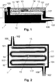
- Reference numeral 1 denotes a flow sensor for measuring the flow of fluids, preferably air or other gases.
- the flow sensor 1 comprises a cover plate 12 and a base body 1 ', which in various embodiments in the Figures 2 . 5 . 7a and 7b is shown.
- the cover plate 12 is mounted on the base body 1 'and fastened to the base body 1', for example by means of rivets 103, screws, adhesive or by welding.
- the cover plate 12 is, for example, a plan executed electronic circuit board (electronic printed circuit board) made of epoxy.
- the main body 1 comprises a non-elastic region 10 and an elastic region 11 connected thereto.
- the elastic region 11 is arranged lying on the non-elastic region 10.
- the non-elastic, or at least compared to the elastic region 11 substantially less elastic and harder region 10 consists for example of a plastic such as nylon.
- the elastic (softer) portion 11 is made of, for example, a thermoplastic material, e.g. a material based on polyethylene.
- the main body 1 ' is preferably produced in a two-component injection molding process. In the two-component injection molding process, the elastic and non-elastic regions 10, 11 are connected to one another, for example, via a material connection or at least in a form-fitting manner.
- the elastic region 11 and the non-elastic region 10 are made as separate parts, e.g. as a base plate and channel plate, which are joined together, for example by gluing.
- the non-elastic portion 10 (the base plate) comprises two terminals 100 for feeding and Removal of the flow medium.
- the connections 100 are preferably designed for the attachment of hoses, which for example have an inner diameter of 6 mm.
- the terminals 100 are configured conical and provided for example with radial ribs.
- the connections 100 have an inner bore 102 with a diameter of approximately 0.5 mm.
- FIGS. 3a, 3b, 3c and 3d Examples are shown with different arrangements of the terminals 100.
- the flow sensor 1 cuboid shaped and the terminals 100 are arranged side by side on a common side (eg front side) of the cuboid.
- the flow sensor 1 is cuboid-shaped and the connections 100 are arranged on different sides of the cuboid, for example on opposite sides along a common axis.
- the flow sensor 1 is cylindrically shaped and the connections 100 are arranged opposite one another along a common axis.
- the flow sensor 1 is U-shaped and the connections 100 are respectively arranged at one of the two ends of the U-shape (horseshoe).
- the elastic region 11 (the channel plate) comprises a flow channel 14.
- the flow channel 14 has a flat running channel bed 141 with a smooth surface and is covered by the arranged parallel to the channel bed 141 cover plate 12.
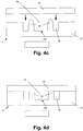
- the flow channel 14 on a multiple meandering between its two ends course.
- the flow channel is connected in each case through a bore 101 with the inner bore 102 of one of the connections 100.
- the holes 101 extend from the channel bed 141 through the elastic portion 11 and the non-elastic portion 10 to the Inner bores 102 of the terminals 100 and are arranged, for example, perpendicular to the channel bed 141 and to the inner bores 102.
- the elastic region 11 comprises a sealing lip 15, which is arranged standing on the channel bed 141 and extends from the channel bed 141 to the cover plate 12.
- the flow channel 14 is formed by the sealing lip 15, which circulates the channel bed 141 of the flow channel 14 and laterally delimits the flow channel 14 on the channel bed 141 along the direction of flow.
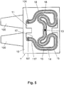
- FIGS. 4a and 4c is shown in cross-section transverse to the flow direction of the flow channel 14, the sealing lip 15 on the side facing away from the channel bed 141 a taper when the cover plate 12 is not mounted on the base body 1 '.
- the sealing lip 15 When the cover plate 12 is mounted on the base body 1 ', the sealing lip 15 is compressed as in FIGS FIGS. 4b . 4d is schematically illustrated, and the sealing lip 15 seals the flow channel 14 against the cover plate 12 from.
- the cover plate 12, the channel bed 141 and the sealing lip 15 each have smooth surfaces and form interfaces which form the flow channel 14 and define a constant, preferably rectangular cross-section.
- the cross section of the flow channel 14 has, for example, a depth of 0.3 mm and a width of 0.8 mm.
- the length of the flow channel 14 is for example 100mm.
- the flow channel 14 has a length that is large in relation to its cross section, for example, the ratio of length to width or length to depth of the flow channel 14 is in the range of about 100: 1 to 400: 1.
- the Reynolds number of the flow channel 14 is about 50, which causes a turbulence and vortex laminar flow.
- the flow channel 14 formed by the sealing lip 15 is circulated by an outer channel 18, is limited by the edges 117 of the non-elastic region 10 and by the sealing lips 15 over the entire sensor base body 1 'seen.
- These edges 117 of the non-elastic region 10 may also be called spacers 117 or reference plane webs 117.
- these spacers 117 are the webs projecting here at two opposite ends of the non-elastic body 10 into the region of the elastic region 11, thus of the main body 1 '. They form with their circumferential housing surface a reference plane 217th In the FIG. 2
- These spacers are shown as circumferential housing edge webs 117.
- the spacers 117 need not be arranged circumferentially. It is sufficient if these are designed such that a defined against the channel bed 141 surface plane 217 is generated, which are lower than the protruding beyond them sealing lips 15.
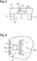
- FIG. 5 is exemplarily in the vicinity of a terminal 101 at two opposite points of the other figures provided with the reference numeral 17 elastic web of the elastic portion 11 and the reference numeral 117 provided in the other figures, non-elastic web of the non-elastic housing part 10 is located.
- FIGS. 7a and 7b It can be seen that with the non-elastic spacers 117, a reference plane 217 is defined, which lie - compared to the channel bed 141 - deeper than the sealing lips 15 projecting beyond them.
- a reference plane 217 is defined, which lie - compared to the channel bed 141 - deeper than the sealing lips 15 projecting beyond them.
- a very long channel path 14 ie a high aspect ratio, can easily be achieved by a meandering shape.
- the curve shape of the channel expressed in the word meander improves the laminar flow. But it would also be possible to arrange several channels 14 directly next to each other and to design the deflection on one side in each case via a more or less U-shaped 180 ° deflection.
- the flow sensor 1 comprises a flow sensor element 13, which is embedded in the cover plate 12 and adjacent to the flow channel 14.
- the flow sensor element 13 is embedded flush in the cover plate 12, so that the cover plate 12 and the flow sensor element 13 form a substantially planar surface to cover the flow channel 14 in order to avoid the formation of vortices and turbulence.
- the flow sensor element 13 is glued to the cover plate 12, but other fastening means are possible, such as screws or snaps.
- the FIG. 6 shows a cross section through a portion of the flow channel 14 along the flow direction, which illustrates an example of a flush arrangement of the flow sensor element 13 in the cover plate 12.
- the flow sensor element 13 has a thinned region which forms a cavity 16 between the flow sensor element 13 and the cover plate 12.
- the flow sensor element 13 is a manufactured in thin or thick film technology element having a plurality of sensor elements, for example, at least one or two temperature sensors 131, 133, or a differential temperature sensor and a heating element 133. It is also possible a the temperature sensors 131, 133 to use as a heating element. It should be added at this point that the medium temperature can be detected both in the flow channel 14 and on the electronic circuit board of the cover plate 12, since the medium assumes the housing temperature of the flow sensor 1 by the very low flow in the flow channel 14, that is, in a variant the temperature sensor for determining the temperature of the medium outside the flow channel 14 is arranged on the cover plate 12.
- the sensor elements 131, 132, 133 of the flow sensor element 13 are connected via printed conductors to an electronic circuit mounted on the cover plate 12.
- the electronic circuit preferably comprises a programmable processor, in particular a PSoC (Programmable System on Chip) with an integrated programmable analog part (amplifier, A / D converter, etc.). Either the heat transfer from the heating element 132 to one of the temperature sensors 133 or the cooling of the heating element 132 by the passing medium is measured, in order to determine thereon the flow velocity and thereby the flow in the flow channel 14.
- the cover plate 12 has a cavity 130 in which the flow sensor element 13 with one or more sensors as to FIG. 6 is explained. It is a the cover plate 12 piercing Signalausausment 132 shown in a corresponding channel 131. Since preferably the flow sensor element 13 is enclosed in the cavity 130 by means of sealing backfill material, the flow channel 14, which is schematically indicated laterally bounded by the seal lips 15 and (not shown) by the channel bed 141, is very well sealed, also for example small To be able to measure pressure differences well.
- FIG. 9 shows a bottom view of another implementation of the Signalausaus exchange, which is particularly advantageous in a single-sided printed circuit board 12.
- the flow sensor element 13 is embedded.
- the printed circuit board at least one, but advantageously two separate Signalausaus exchangesnuten 231 are provided, in which signal conductors are guided as a cable or as a foil in a region 230 of the printed circuit board 12 for further processing in there provided electronic components.
- the cavities 130 and 231 are filled with a sealing material, so that the lead-out below the sealing lip 15 does not affect the function of the sensors.
- a smooth printed circuit board 12 allows as a counterpart to the elastic sealing lips 15 an arbitrarily defined curving and designed as a meander shape of the fluid channel, so that a high aspect ratio can be created in a small space without endangering a laminar flow.
- cover plate 12 and webs 117 it is also possible to ensure by appropriate surface design of the cover plate 12 and webs 117 that a defined spatial position of cover plate 12 and base 1/1 'is achieved, so that the sensor element 13 and electrical connections come to rest at predetermined locations.
- FIGS. 7a and 7b two sealing lips 15 are shown, the shows FIG. 6 in that, with the corresponding design of the elastic region 11 with fluid connections through the bottom, there is actually only a single toroidal sealing lip 15 which forms the complete lateral boundary of the fluid channel 14.
- FIG. 10 shows a further embodiment of the signal execution.
- the flow sensor element 13 is embedded.
- the active sensor surface has been given the reference numeral 134 to be similar to that of the FIG. 6 to point to individual sensors.
- the flow sensor element 13 thus has its own printed circuit board, on which at least two, here four separate signal lines 331 are provided, which terminate in contact surfaces 332 of the sensor element 13. These contact surfaces 332 of the sensor element 13 are located opposite contact surfaces 333 of the cover plate 12, from which then not shown signal lines are continued in a conventional manner.
- connection between the contact surfaces 332 and 333 are provided by bonding wires 334, which in the side view of FIG. 11 protected with a potting compound 335.
- the sensor element 13 so larger than the channel width of the channel 14, but the sensor-active surface 134 is only part of it.
- the signal lines are guided under one of the sealing lips 15.
- the transition to the cover plate or circuit board 12 is done here by means of bonding technology.
- the bonding wires 334 are finally protected by a potting compound 335.
Landscapes
- Physics & Mathematics (AREA)
- Fluid Mechanics (AREA)
- General Physics & Mathematics (AREA)
- Measuring Volume Flow (AREA)
Priority Applications (1)
| Application Number | Priority Date | Filing Date | Title |
|---|---|---|---|
| EP08787351.9A EP2180951B1 (de) | 2007-08-21 | 2008-08-20 | Durchflusssensor und herstellungsverfahren dafür |
Applications Claiming Priority (3)
| Application Number | Priority Date | Filing Date | Title |
|---|---|---|---|
| EP07405244 | 2007-08-21 | ||
| PCT/EP2008/060903 WO2009024589A1 (de) | 2007-08-21 | 2008-08-20 | Durchflusssensor und herstellungsverfahren dafür |
| EP08787351.9A EP2180951B1 (de) | 2007-08-21 | 2008-08-20 | Durchflusssensor und herstellungsverfahren dafür |
Publications (2)
| Publication Number | Publication Date |
|---|---|
| EP2180951A1 EP2180951A1 (de) | 2010-05-05 |
| EP2180951B1 true EP2180951B1 (de) | 2019-09-18 |
Family
ID=38980940
Family Applications (1)
| Application Number | Title | Priority Date | Filing Date |
|---|---|---|---|
| EP08787351.9A Active EP2180951B1 (de) | 2007-08-21 | 2008-08-20 | Durchflusssensor und herstellungsverfahren dafür |
Country Status (6)
| Country | Link |
|---|---|
| US (1) | US8256285B2 (da) |
| EP (1) | EP2180951B1 (da) |
| CN (1) | CN101784343B (da) |
| CA (1) | CA2695486A1 (da) |
| DK (1) | DK2180951T3 (da) |
| WO (1) | WO2009024589A1 (da) |
Families Citing this family (12)
| Publication number | Priority date | Publication date | Assignee | Title |
|---|---|---|---|---|
| WO2012049742A1 (ja) * | 2010-10-13 | 2012-04-19 | 日立オートモティブシステムズ株式会社 | 流量センサおよびその製造方法並びに流量センサモジュールおよびその製造方法 |
| DE102011089608A1 (de) * | 2011-12-22 | 2013-06-27 | Horst Siedle Gmbh & Co. Kg | Gehäuseteil für einen elektrischen Sensorsowie Verfahren zur Herstellung des Gehäuseteils |
| JP5710538B2 (ja) * | 2012-04-06 | 2015-04-30 | 日立オートモティブシステムズ株式会社 | 流量センサ |
| US10107095B2 (en) * | 2013-10-17 | 2018-10-23 | Weatherford Technology Holdings, Llc | Apparatus and method for monitoring a fluid |
| WO2018138967A1 (ja) * | 2017-01-26 | 2018-08-02 | 日立オートモティブシステムズ株式会社 | 熱式流量計 |
| AT520605B1 (de) * | 2017-11-10 | 2020-03-15 | Erba Tech Austria Gmbh | Sensorkassette |
| CN107715932B (zh) * | 2017-11-23 | 2023-06-16 | 昌微系统科技(上海)有限公司 | 一种微流体器件 |
| DE102020116704A1 (de) | 2019-07-15 | 2021-01-21 | Endress+Hauser Conducta Gmbh+Co. Kg | Fluidführungsmodul und Fluidführungssystem mit mindestens zwei Fluidführungsmodulen |
| US11280649B2 (en) * | 2019-10-21 | 2022-03-22 | Flusso Limited | Sensor assembly |
| CN113075419A (zh) * | 2021-03-31 | 2021-07-06 | 苏州容启传感器科技有限公司 | 一种风速风向检测装置 |
| CN113413936B (zh) * | 2021-08-24 | 2021-11-30 | 北京寻因生物科技有限公司 | 一种流量调节结构及微流体芯片 |
| CN114608666B (zh) * | 2022-05-09 | 2022-08-26 | 苏州敏芯微电子技术股份有限公司 | 流量传感器封装结构及封装方法 |
Family Cites Families (13)
| Publication number | Priority date | Publication date | Assignee | Title |
|---|---|---|---|---|
| US5385046A (en) * | 1992-04-10 | 1995-01-31 | Honda Giken Kogyo Kabushiki Kaisha | Gas flow type angular velocity sensor |
| US7258003B2 (en) * | 1998-12-07 | 2007-08-21 | Honeywell International Inc. | Flow sensor with self-aligned flow channel |
| US6615856B2 (en) * | 2000-08-04 | 2003-09-09 | Biomicro Systems, Inc. | Remote valving for microfluidic flow control |
| US6729181B2 (en) | 2000-08-23 | 2004-05-04 | Sensiron Ag | Flow sensor in a housing |
| US6952962B2 (en) | 2000-10-24 | 2005-10-11 | Sandia National Laboratories | Mobile monolithic polymer elements for flow control in microfluidic devices |
| WO2003010289A2 (en) | 2001-07-25 | 2003-02-06 | The Trustees Of Princeton University | Nanochannel arrays and their preparation and use for high throughput macromolecular analysis |
| EP1975628B1 (en) | 2002-04-30 | 2012-01-25 | ARKRAY, Inc. | Analytical instrument |
| DE10239597B4 (de) * | 2002-08-28 | 2005-03-17 | Fresenius Medical Care Deutschland Gmbh | Einwegkassette |
| US6782745B1 (en) * | 2003-02-21 | 2004-08-31 | Visteon Global Technologies, Inc. | Slosh supressor and heat sink |
| EP1620205A2 (en) | 2003-04-04 | 2006-02-01 | Tecan Trading AG | Elastomeric tools for fabricating of polymeric devices and uses thereof |
| US7419639B2 (en) | 2004-05-12 | 2008-09-02 | The Board Of Trustees Of The Leland Stanford Junior University | Multilayer microfluidic device |
| EP2415524A2 (en) | 2005-03-30 | 2012-02-08 | F. Hoffmann-La Roche AG | Sealed Device |
| JP5052275B2 (ja) * | 2007-09-20 | 2012-10-17 | アズビル株式会社 | フローセンサの取付構造 |
-
2008
- 2008-08-20 EP EP08787351.9A patent/EP2180951B1/de active Active
- 2008-08-20 CA CA2695486A patent/CA2695486A1/en not_active Abandoned
- 2008-08-20 DK DK08787351T patent/DK2180951T3/da active
- 2008-08-20 CN CN200880103855XA patent/CN101784343B/zh not_active Expired - Fee Related
- 2008-08-20 WO PCT/EP2008/060903 patent/WO2009024589A1/de not_active Ceased
- 2008-08-20 US US12/674,109 patent/US8256285B2/en active Active
Non-Patent Citations (1)
| Title |
|---|
| None * |
Also Published As
| Publication number | Publication date |
|---|---|
| US20110036162A1 (en) | 2011-02-17 |
| DK2180951T3 (da) | 2019-12-02 |
| CN101784343A (zh) | 2010-07-21 |
| CN101784343B (zh) | 2013-01-23 |
| US8256285B2 (en) | 2012-09-04 |
| CA2695486A1 (en) | 2009-02-26 |
| EP2180951A1 (de) | 2010-05-05 |
| WO2009024589A1 (de) | 2009-02-26 |
Similar Documents
| Publication | Publication Date | Title |
|---|---|---|
| EP2180951B1 (de) | Durchflusssensor und herstellungsverfahren dafür | |
| DE19524634B4 (de) | Vorrichtung zur Messung der Masse eines strömenden Mediums | |
| EP2326923B1 (de) | Sensoranordnung zur bestimmung eines parameters eines fluiden mediums | |
| EP3076851A1 (de) | Endoskopkopf und endoskop | |
| DE102015004049B4 (de) | Ultraschallzähler | |
| WO2013143931A1 (de) | Stützeinheit für eine leiterplatte in einer sensoreinheit und korrespondierende sensoreinheit | |
| EP3108213B1 (de) | Sensoranordnung zur bestimmung wenigstens eines parameters eines durch einen kanal strömenden fluiden mediums | |
| DE19700393C2 (de) | Gehäuse mit einer Halbleiter-Sensoranordnung und Verfahren zu deren Herstellung | |
| DE102004026210A1 (de) | Vorrichtung zur Erfassung einer physikalischen Größe und Gehäuse für eine Anordnung zur Messung einer physikalischen Größe | |
| EP1236037B1 (de) | Sensor in einem gehäuse | |
| EP0997712B1 (de) | Kapazitive Sensoranordnung zur Verwendung in einem flüssigen Medium sowie Herstellungsverfahren und Verwendung | |
| EP1353160B1 (de) | Drucksensor | |
| DE102015206677A1 (de) | Sensor zur Bestimmung wenigstens eines Parameters eines durch einen Messkanal strömenden fluiden Mediums | |
| EP3769061A1 (de) | Ortsauflösender taktiler sensor und herstellungsverfahren für einen ortsauflösenden taktilen sensor | |
| EP2522427B1 (de) | Mikrofluidvorrichtung und Verfahren zum Herstellen derselben | |
| DE102004021303A1 (de) | Durchflussmessgerät | |
| EP0943076A1 (de) | Mikromechanisch gefertigte flussrestriktionsvorrichtung | |
| EP1087224B1 (de) | Elektrochemische Messvorrichtung mit planarem Sensorträger | |
| EP4159144B1 (de) | Fluidsteueranordnung für ein medizinisches gerät | |
| DE10059813A1 (de) | Vorrichtung zur Erfassung eines Fluiddrucks | |
| DE102008032309A1 (de) | Sensoranordnung zur Messung des Zustands einer Flüssigkeit, insbesondere von Öl | |
| EP2714583B1 (de) | Mikrofluidische vorrichtung mit elektronischem bauteil und federelement | |
| DE3730702A1 (de) | Kraftaufnehmer | |
| DE4105676C1 (en) | Electrostatic pump or flow velocity sensor - has seal around flow aperture mounted on surface of semiconductor device | |
| DE29701418U1 (de) | Mikromechanisch gefertigte Flußrestriktionsvorrichtung |
Legal Events
| Date | Code | Title | Description |
|---|---|---|---|
| PUAI | Public reference made under article 153(3) epc to a published international application that has entered the european phase |
Free format text: ORIGINAL CODE: 0009012 |
|
| 17P | Request for examination filed |
Effective date: 20100122 |
|
| AK | Designated contracting states |
Kind code of ref document: A1 Designated state(s): AT BE BG CH CY CZ DE DK EE ES FI FR GB GR HR HU IE IS IT LI LT LU LV MC MT NL NO PL PT RO SE SI SK TR |
|
| AX | Request for extension of the european patent |
Extension state: AL BA MK RS |
|
| 17Q | First examination report despatched |
Effective date: 20100929 |
|
| DAX | Request for extension of the european patent (deleted) | ||
| REG | Reference to a national code |
Ref country code: HK Ref legal event code: DE Ref document number: 1142026 Country of ref document: HK |
|
| REG | Reference to a national code |
Ref country code: HK Ref legal event code: WD Ref document number: 1142026 Country of ref document: HK |
|
| STAA | Information on the status of an ep patent application or granted ep patent |
Free format text: STATUS: EXAMINATION IS IN PROGRESS |
|
| GRAP | Despatch of communication of intention to grant a patent |
Free format text: ORIGINAL CODE: EPIDOSNIGR1 |
|
| STAA | Information on the status of an ep patent application or granted ep patent |
Free format text: STATUS: GRANT OF PATENT IS INTENDED |
|
| INTG | Intention to grant announced |
Effective date: 20190312 |
|
| RIN1 | Information on inventor provided before grant (corrected) |
Inventor name: MEGNET, KARIN Inventor name: STAEHELI, CURDIN Inventor name: HOLOCH, PHILIP |
|
| GRAS | Grant fee paid |
Free format text: ORIGINAL CODE: EPIDOSNIGR3 |
|
| GRAA | (expected) grant |
Free format text: ORIGINAL CODE: 0009210 |
|
| STAA | Information on the status of an ep patent application or granted ep patent |
Free format text: STATUS: THE PATENT HAS BEEN GRANTED |
|
| AK | Designated contracting states |
Kind code of ref document: B1 Designated state(s): AT BE BG CH CY CZ DE DK EE ES FI FR GB GR HR HU IE IS IT LI LT LU LV MC MT NL NO PL PT RO SE SI SK TR |
|
| REG | Reference to a national code |
Ref country code: GB Ref legal event code: FG4D Free format text: NOT ENGLISH |
|
| REG | Reference to a national code |
Ref country code: CH Ref legal event code: EP |
|
| REG | Reference to a national code |
Ref country code: DE Ref legal event code: R096 Ref document number: 502008016897 Country of ref document: DE |
|
| REG | Reference to a national code |
Ref country code: AT Ref legal event code: REF Ref document number: 1180669 Country of ref document: AT Kind code of ref document: T Effective date: 20191015 |
|
| REG | Reference to a national code |
Ref country code: IE Ref legal event code: FG4D Free format text: LANGUAGE OF EP DOCUMENT: GERMAN |
|
| REG | Reference to a national code |
Ref country code: DK Ref legal event code: T3 Effective date: 20191128 |
|
| REG | Reference to a national code |
Ref country code: CH Ref legal event code: NV Representative=s name: ISLER AND PEDRAZZINI AG, CH |
|
| REG | Reference to a national code |
Ref country code: SE Ref legal event code: TRGR |
|
| REG | Reference to a national code |
Ref country code: NL Ref legal event code: MP Effective date: 20190918 |
|
| PG25 | Lapsed in a contracting state [announced via postgrant information from national office to epo] |
Ref country code: HR Free format text: LAPSE BECAUSE OF FAILURE TO SUBMIT A TRANSLATION OF THE DESCRIPTION OR TO PAY THE FEE WITHIN THE PRESCRIBED TIME-LIMIT Effective date: 20190918 Ref country code: BG Free format text: LAPSE BECAUSE OF FAILURE TO SUBMIT A TRANSLATION OF THE DESCRIPTION OR TO PAY THE FEE WITHIN THE PRESCRIBED TIME-LIMIT Effective date: 20191218 Ref country code: LT Free format text: LAPSE BECAUSE OF FAILURE TO SUBMIT A TRANSLATION OF THE DESCRIPTION OR TO PAY THE FEE WITHIN THE PRESCRIBED TIME-LIMIT Effective date: 20190918 Ref country code: NO Free format text: LAPSE BECAUSE OF FAILURE TO SUBMIT A TRANSLATION OF THE DESCRIPTION OR TO PAY THE FEE WITHIN THE PRESCRIBED TIME-LIMIT Effective date: 20191218 |
|
| REG | Reference to a national code |
Ref country code: LT Ref legal event code: MG4D |
|
| PG25 | Lapsed in a contracting state [announced via postgrant information from national office to epo] |
Ref country code: GR Free format text: LAPSE BECAUSE OF FAILURE TO SUBMIT A TRANSLATION OF THE DESCRIPTION OR TO PAY THE FEE WITHIN THE PRESCRIBED TIME-LIMIT Effective date: 20191219 Ref country code: LV Free format text: LAPSE BECAUSE OF FAILURE TO SUBMIT A TRANSLATION OF THE DESCRIPTION OR TO PAY THE FEE WITHIN THE PRESCRIBED TIME-LIMIT Effective date: 20190918 |
|
| PG25 | Lapsed in a contracting state [announced via postgrant information from national office to epo] |
Ref country code: PT Free format text: LAPSE BECAUSE OF FAILURE TO SUBMIT A TRANSLATION OF THE DESCRIPTION OR TO PAY THE FEE WITHIN THE PRESCRIBED TIME-LIMIT Effective date: 20200120 Ref country code: ES Free format text: LAPSE BECAUSE OF FAILURE TO SUBMIT A TRANSLATION OF THE DESCRIPTION OR TO PAY THE FEE WITHIN THE PRESCRIBED TIME-LIMIT Effective date: 20190918 Ref country code: NL Free format text: LAPSE BECAUSE OF FAILURE TO SUBMIT A TRANSLATION OF THE DESCRIPTION OR TO PAY THE FEE WITHIN THE PRESCRIBED TIME-LIMIT Effective date: 20190918 Ref country code: EE Free format text: LAPSE BECAUSE OF FAILURE TO SUBMIT A TRANSLATION OF THE DESCRIPTION OR TO PAY THE FEE WITHIN THE PRESCRIBED TIME-LIMIT Effective date: 20190918 Ref country code: RO Free format text: LAPSE BECAUSE OF FAILURE TO SUBMIT A TRANSLATION OF THE DESCRIPTION OR TO PAY THE FEE WITHIN THE PRESCRIBED TIME-LIMIT Effective date: 20190918 Ref country code: PL Free format text: LAPSE BECAUSE OF FAILURE TO SUBMIT A TRANSLATION OF THE DESCRIPTION OR TO PAY THE FEE WITHIN THE PRESCRIBED TIME-LIMIT Effective date: 20190918 |
|
| PG25 | Lapsed in a contracting state [announced via postgrant information from national office to epo] |
Ref country code: IS Free format text: LAPSE BECAUSE OF FAILURE TO SUBMIT A TRANSLATION OF THE DESCRIPTION OR TO PAY THE FEE WITHIN THE PRESCRIBED TIME-LIMIT Effective date: 20200224 Ref country code: SK Free format text: LAPSE BECAUSE OF FAILURE TO SUBMIT A TRANSLATION OF THE DESCRIPTION OR TO PAY THE FEE WITHIN THE PRESCRIBED TIME-LIMIT Effective date: 20190918 Ref country code: CZ Free format text: LAPSE BECAUSE OF FAILURE TO SUBMIT A TRANSLATION OF THE DESCRIPTION OR TO PAY THE FEE WITHIN THE PRESCRIBED TIME-LIMIT Effective date: 20190918 |
|
| REG | Reference to a national code |
Ref country code: DE Ref legal event code: R097 Ref document number: 502008016897 Country of ref document: DE |
|
| PLBE | No opposition filed within time limit |
Free format text: ORIGINAL CODE: 0009261 |
|
| STAA | Information on the status of an ep patent application or granted ep patent |
Free format text: STATUS: NO OPPOSITION FILED WITHIN TIME LIMIT |
|
| PG2D | Information on lapse in contracting state deleted |
Ref country code: IS |
|
| PG25 | Lapsed in a contracting state [announced via postgrant information from national office to epo] |
Ref country code: IS Free format text: LAPSE BECAUSE OF FAILURE TO SUBMIT A TRANSLATION OF THE DESCRIPTION OR TO PAY THE FEE WITHIN THE PRESCRIBED TIME-LIMIT Effective date: 20200119 |
|
| 26N | No opposition filed |
Effective date: 20200619 |
|
| PG25 | Lapsed in a contracting state [announced via postgrant information from national office to epo] |
Ref country code: SI Free format text: LAPSE BECAUSE OF FAILURE TO SUBMIT A TRANSLATION OF THE DESCRIPTION OR TO PAY THE FEE WITHIN THE PRESCRIBED TIME-LIMIT Effective date: 20190918 |
|
| REG | Reference to a national code |
Ref country code: FI Ref legal event code: MAE |
|
| REG | Reference to a national code |
Ref country code: DK Ref legal event code: EBP Effective date: 20200831 |
|
| REG | Reference to a national code |
Ref country code: SE Ref legal event code: EUG |
|
| PG25 | Lapsed in a contracting state [announced via postgrant information from national office to epo] |
Ref country code: MC Free format text: LAPSE BECAUSE OF FAILURE TO SUBMIT A TRANSLATION OF THE DESCRIPTION OR TO PAY THE FEE WITHIN THE PRESCRIBED TIME-LIMIT Effective date: 20190918 |
|
| GBPC | Gb: european patent ceased through non-payment of renewal fee |
Effective date: 20200820 |
|
| PG25 | Lapsed in a contracting state [announced via postgrant information from national office to epo] |
Ref country code: FI Free format text: LAPSE BECAUSE OF NON-PAYMENT OF DUE FEES Effective date: 20200820 Ref country code: LU Free format text: LAPSE BECAUSE OF NON-PAYMENT OF DUE FEES Effective date: 20200820 |
|
| REG | Reference to a national code |
Ref country code: BE Ref legal event code: MM Effective date: 20200831 |
|
| PG25 | Lapsed in a contracting state [announced via postgrant information from national office to epo] |
Ref country code: SE Free format text: LAPSE BECAUSE OF NON-PAYMENT OF DUE FEES Effective date: 20200821 |
|
| PG25 | Lapsed in a contracting state [announced via postgrant information from national office to epo] |
Ref country code: FR Free format text: LAPSE BECAUSE OF NON-PAYMENT OF DUE FEES Effective date: 20200831 |
|
| PG25 | Lapsed in a contracting state [announced via postgrant information from national office to epo] |
Ref country code: BE Free format text: LAPSE BECAUSE OF NON-PAYMENT OF DUE FEES Effective date: 20200831 Ref country code: DK Free format text: LAPSE BECAUSE OF NON-PAYMENT OF DUE FEES Effective date: 20200831 Ref country code: GB Free format text: LAPSE BECAUSE OF NON-PAYMENT OF DUE FEES Effective date: 20200820 Ref country code: IE Free format text: LAPSE BECAUSE OF NON-PAYMENT OF DUE FEES Effective date: 20200820 |
|
| REG | Reference to a national code |
Ref country code: AT Ref legal event code: MM01 Ref document number: 1180669 Country of ref document: AT Kind code of ref document: T Effective date: 20200820 |
|
| PG25 | Lapsed in a contracting state [announced via postgrant information from national office to epo] |
Ref country code: AT Free format text: LAPSE BECAUSE OF NON-PAYMENT OF DUE FEES Effective date: 20200820 Ref country code: IT Free format text: LAPSE BECAUSE OF NON-PAYMENT OF DUE FEES Effective date: 20200820 |
|
| PG25 | Lapsed in a contracting state [announced via postgrant information from national office to epo] |
Ref country code: TR Free format text: LAPSE BECAUSE OF FAILURE TO SUBMIT A TRANSLATION OF THE DESCRIPTION OR TO PAY THE FEE WITHIN THE PRESCRIBED TIME-LIMIT Effective date: 20190918 Ref country code: MT Free format text: LAPSE BECAUSE OF FAILURE TO SUBMIT A TRANSLATION OF THE DESCRIPTION OR TO PAY THE FEE WITHIN THE PRESCRIBED TIME-LIMIT Effective date: 20190918 Ref country code: CY Free format text: LAPSE BECAUSE OF FAILURE TO SUBMIT A TRANSLATION OF THE DESCRIPTION OR TO PAY THE FEE WITHIN THE PRESCRIBED TIME-LIMIT Effective date: 20190918 |
|
| P01 | Opt-out of the competence of the unified patent court (upc) registered |
Effective date: 20230523 |
|
| PGFP | Annual fee paid to national office [announced via postgrant information from national office to epo] |
Ref country code: CH Payment date: 20230902 Year of fee payment: 16 |
|
| REG | Reference to a national code |
Ref country code: CH Ref legal event code: PL |
|
| PG25 | Lapsed in a contracting state [announced via postgrant information from national office to epo] |
Ref country code: CH Free format text: LAPSE BECAUSE OF NON-PAYMENT OF DUE FEES Effective date: 20240831 |
|
| PGFP | Annual fee paid to national office [announced via postgrant information from national office to epo] |
Ref country code: DE Payment date: 20250819 Year of fee payment: 18 |