EP2180971B1 - Porte-pièce destiné à recevoir une pièce à usiner, notamment en forme de plaque, dans une installation d'usinage - Google Patents
Porte-pièce destiné à recevoir une pièce à usiner, notamment en forme de plaque, dans une installation d'usinage Download PDFInfo
- Publication number
- EP2180971B1 EP2180971B1 EP07801765A EP07801765A EP2180971B1 EP 2180971 B1 EP2180971 B1 EP 2180971B1 EP 07801765 A EP07801765 A EP 07801765A EP 07801765 A EP07801765 A EP 07801765A EP 2180971 B1 EP2180971 B1 EP 2180971B1
- Authority
- EP
- European Patent Office
- Prior art keywords
- support
- workpiece
- shifting
- workpiece support
- adjustment element
- Prior art date
- Legal status (The legal status is an assumption and is not a legal conclusion. Google has not performed a legal analysis and makes no representation as to the accuracy of the status listed.)
- Not-in-force
Links
- 238000003754 machining Methods 0.000 title claims abstract description 13
- 238000009434 installation Methods 0.000 title abstract 2
- 238000005520 cutting process Methods 0.000 claims abstract description 8
- 230000033001 locomotion Effects 0.000 claims description 62
- 230000004888 barrier function Effects 0.000 claims description 9
- 239000012530 fluid Substances 0.000 claims description 7
- 238000001514 detection method Methods 0.000 claims description 3
- 238000000034 method Methods 0.000 claims description 3
- 238000006073 displacement reaction Methods 0.000 abstract description 66
- 238000012545 processing Methods 0.000 description 22
- 238000012546 transfer Methods 0.000 description 8
- 238000012544 monitoring process Methods 0.000 description 6
- 238000003860 storage Methods 0.000 description 5
- 238000003698 laser cutting Methods 0.000 description 3
- 239000000463 material Substances 0.000 description 3
- 238000003466 welding Methods 0.000 description 3
- 238000011161 development Methods 0.000 description 2
- 230000018109 developmental process Effects 0.000 description 2
- 238000005452 bending Methods 0.000 description 1
- 239000000969 carrier Substances 0.000 description 1
- 238000011109 contamination Methods 0.000 description 1
- 238000013461 design Methods 0.000 description 1
- -1 for example Substances 0.000 description 1
- 230000001771 impaired effect Effects 0.000 description 1
- 238000003780 insertion Methods 0.000 description 1
- 230000037431 insertion Effects 0.000 description 1
- 238000002844 melting Methods 0.000 description 1
- 230000008018 melting Effects 0.000 description 1
- 230000002028 premature Effects 0.000 description 1
- 230000001105 regulatory effect Effects 0.000 description 1
Images




Classifications
-
- B—PERFORMING OPERATIONS; TRANSPORTING
- B23—MACHINE TOOLS; METAL-WORKING NOT OTHERWISE PROVIDED FOR
- B23K—SOLDERING OR UNSOLDERING; WELDING; CLADDING OR PLATING BY SOLDERING OR WELDING; CUTTING BY APPLYING HEAT LOCALLY, e.g. FLAME CUTTING; WORKING BY LASER BEAM
- B23K26/00—Working by laser beam, e.g. welding, cutting or boring
- B23K26/36—Removing material
- B23K26/38—Removing material by boring or cutting
-
- B—PERFORMING OPERATIONS; TRANSPORTING
- B23—MACHINE TOOLS; METAL-WORKING NOT OTHERWISE PROVIDED FOR
- B23K—SOLDERING OR UNSOLDERING; WELDING; CLADDING OR PLATING BY SOLDERING OR WELDING; CUTTING BY APPLYING HEAT LOCALLY, e.g. FLAME CUTTING; WORKING BY LASER BEAM
- B23K26/00—Working by laser beam, e.g. welding, cutting or boring
- B23K26/08—Devices involving relative movement between laser beam and workpiece
-
- B—PERFORMING OPERATIONS; TRANSPORTING
- B23—MACHINE TOOLS; METAL-WORKING NOT OTHERWISE PROVIDED FOR
- B23K—SOLDERING OR UNSOLDERING; WELDING; CLADDING OR PLATING BY SOLDERING OR WELDING; CUTTING BY APPLYING HEAT LOCALLY, e.g. FLAME CUTTING; WORKING BY LASER BEAM
- B23K26/00—Working by laser beam, e.g. welding, cutting or boring
- B23K26/70—Auxiliary operations or equipment
- B23K26/702—Auxiliary equipment
-
- B—PERFORMING OPERATIONS; TRANSPORTING
- B23—MACHINE TOOLS; METAL-WORKING NOT OTHERWISE PROVIDED FOR
- B23K—SOLDERING OR UNSOLDERING; WELDING; CLADDING OR PLATING BY SOLDERING OR WELDING; CUTTING BY APPLYING HEAT LOCALLY, e.g. FLAME CUTTING; WORKING BY LASER BEAM
- B23K37/00—Auxiliary devices or processes, not specially adapted for a procedure covered by only one of the other main groups of this subclass
- B23K37/04—Auxiliary devices or processes, not specially adapted for a procedure covered by only one of the other main groups of this subclass for holding or positioning work
- B23K37/0408—Auxiliary devices or processes, not specially adapted for a procedure covered by only one of the other main groups of this subclass for holding or positioning work for planar work
Definitions
- the invention relates to a workpiece support for receiving a workpiece in a processing system, in particular a laser processing system, which processes the workpiece with a cutting beam.
- a workpiece support which has a frame with a plurality of support elements, preferably arranged parallel to one another, on which the at least one workpiece to be machined rests.
- the support elements have at regular intervals Tragticianspitzen and form a support pad for the or the workpieces.
- Such laser processing systems comprise a relative to the workpiece support movable laser cutting head to in a Laser beam a stationary workpiece, which rests on the Tragticianspitzen the support elements to edit.
- laser machining systems are known in which the workpiece support and / or the laser cutting head are movable.
- a workpiece support for receiving a workpiece in a processing plant in which the workpiece support consists of fixed frame parts with slots for receiving the support elements of movable frame parts.
- the fixed frame parts are attached to the frame.
- the movable frame parts are arranged with an outer end on a crank, so that they can perform a reciprocating motion when operating the crank.
- This reciprocating motion of the frame parts is at right angles to the longitudinal extent of the support elements, at least not provided in the longitudinal direction of the support elements. This makes it possible that the support elements partly outside the effective range of the Cutting beam are positioned.
- the support elements are transferred from a first wave-shaped position into a counter-wave-shaped position, wherein the support elements are each braced to their arrangement in the slots.
- This arrangement has the disadvantage that a forced movement of the position of the support elements is introduced transversely to its longitudinal extent by a crank movement. Although such a forced movement has the advantage that an overloading of the support webs does not occur due to their bending, however, by this crank movement in the longitudinal direction of the support elements aligned sliding movement is not possible, so that in the points of contact with the movable and fixed frame parts it to welds on the edge and can come to premature wear.
- each support element can be actuated by a displacement device in order to transfer the support elements from a reference position or active position into an inactive position depending on the geometry of the workpiece or workpieces to be processed. This can ensure the quality of the processing.
- the invention is therefore based on the object to propose a workpiece support for a processing plant, in which an overload of the components involved in the sliding movement of the processing system at the beginning or during a sliding operation, the between a reference position and an inactive position is avoided.
- an overload protection device for positioning of the support elements or between a reference position and any intermediate position in a displacement device in which the support element extends, damage to the components involved in the sliding movement of the processing system is prevented.
- a sliding overload protection device By acting on a sliding overload protection device, the exceeding of a predetermined adjusting force for the sliding movement of the support elements is detected and / or monitored, so that when the adjustment force is exceeded, the sliding movement is not continued or interrupted with the displacement force provided for the displacement.
- a displacement movement of the support elements is then at least impaired and causes an increased adjustment when individual sections of the support elements adhere to the support elements receiving support elements or other components by dirt, caking or welding to the support elements or components.
- the overload protection device thus prevents damage to the components of the processing system involved in the displacement movement at the beginning or during the displacement movement due to an overload. This is an increased life Given the workpiece support with its components due to the avoidance of damage to the overload.
- the overload protection device at least during the sliding movement with the displacement device and the at least one support element is engaged.
- the displacement force occurring between the support element (s) and the displacement device can be detected, so that, in the event of an overload, an immediate decoupling of the displacement movement caused by the displacement device takes place to the support element (s).
- the displacement movement of the at least one support element is preferably stopped when an overload occurs. As a result, damage to the components involved in the sliding movement of the processing system can be avoided. At the same time, the sliding movement of the displacement unit can be continued, so that further support elements, which are actuated by the displacement unit, are transferred to an inactive position, intermediate position or reference position.
- the overload protection device comprises a driver engaging on a positioning element and an actuating element which can be acted upon by the adjusting force.
- the actuator is preferably adjustable to a minimum force to displace the support members held by the support members.
- the actuator allows for an overload a relative movement of the driver to the actuator, so that in a continuation of the sliding movement by the displacement device on the or the support elements caused to a predetermined adjustment displacement movement is interrupted.
- the actuating element can be acted upon by a fluid Lifting cylinder exists.
- a cost-effective design for an overload protection device can be made possible.
- the actuator can also be designed as a servomotor with a sensor or overload clutch.
- further actuators can be provided.
- a piston rod of the lifting cylinder during a displacement movement of the support elements is adjustable to a defined position, so that the displacement force occurring during the displacement movement works against a predetermined in the lifting cylinder chamber or storage volume of the fluid.
- the actuator designed as a lifting cylinder can not only be used for a separate sliding movement of the support element of the support element, but also form an overload protection in which, for example, determine the pressure in the storage chamber of the lifting cylinder and the piston surface of the lifting cylinder a defined adjustment and define an overload point ,
- the preset chamber volume for displacing the maximum adjustment force is displaced from the lifting cylinder, thereby interrupting the displacement movement of the support element despite the further movement of the displacement unit.
- For outflow of the chamber volume in case of overload pressure control valves may preferably be used.
- the actuating element designed as a lifting cylinder comprises a double-stroke cylinder or a cylinder acting on both sides, so that an overload can be detected independently of the displacement direction.
- the overload protection device is attached to a displacement device, which, preferably from below, in an engaged position for Positioning element of the or the support elements is retractable, so that the arranged on the actuating element driver and the positioning element engage with each other.
- a displacement device which, preferably from below, in an engaged position for Positioning element of the or the support elements is retractable, so that the arranged on the actuating element driver and the positioning element engage with each other.
- the driver of the overload protection device comprises two spaced apart driver elements, which are arranged at a distance from each other, which is determined by the respective end position of the positioning of the support elements in a reference position and inactive position. This makes it possible that engagement or engagement of the overload protection device is made possible regardless of the preset position of the or the support elements. If the support element is in an active or in a reference position, the driver element engages during a displacement movement only in an end position of the actuating element on the positioning of the support element. If the support element is in an inactive position, the driver element engages immediately after the transfer of the displacement device in an engaged position on the positioning of the support element and causes the displacement movement. In addition, can be converted by this embodiment, a support element in a reference position, intermediate position or in an inactive position, which has taken an intermediate position between the two positions.
- the overload protection device which is preferably formed by a lifting cylinder with a piston rod, has the advantage that this overload protection device can be activated after the transfer device has been transferred to a reference position a translational movement to transfer the or the support elements of the reference position in an inactive or an intermediate position.
- the piston rod of the actuating element is preferably retracted or in an end position before the engagement position of the displacement device is taken on the support element.
- the overload protection device is aligned to the displacement device that is claimed for a controllable displacement movement of the support elements or from an inactive position to an intermediate position or in a reference position, the piston rod of the actuating element to train and against Storage volume in the lifting cylinder works.
- the end position of the or the driver is detected after a displacement movement of the displacement device by a light barrier or sensors.
- the monitoring by means of a light barrier has the advantage that a plurality of carriers arranged on a displacement device can be monitored together.
- the advantage of sensors, which are each assigned to a driver, is that each driver can be detected individually with respect to the assumed position.
- control element of the overload protection device consists of a magnetic lifting cylinder.
- a fluid such as, for example, air, oil or gel
- an electrical actuation of the driver can be made possible.
- the operation and control of the magnetic lifting cylinder is analogous to the acted upon by a fluid lifting cylinder, as described above.
- an actuating element for an overload protection device which comprises a prestressed spring with preferably a constant spring characteristic which acts on a piston rod.
- This embodiment also allows an analogous operation, such as the above-described embodiment of a fluid-actuated lifting cylinder.
- the actuating element cooperates with a trained as a pivot lever driver which engages with one end to a positioning of the support element and is releasably connected at its opposite end to a piston rod of the actuating element and is rotatably mounted about a arranged on the displacement device pivot axis.
- a trained as a pivot lever driver which engages with one end to a positioning of the support element and is releasably connected at its opposite end to a piston rod of the actuating element and is rotatably mounted about a arranged on the displacement device pivot axis.
- the driver of the alternative embodiment has at a the adjusting element associated end a detent recess, which is followed on both sides by a link. This makes it possible that a holding element of the actuating element engages in the latching recess and secures the driver in a defined position. As soon as an overload which exceeds the adjustment force occurs, a release of the connection between the retaining element of the actuating element and the latching recess of the driver is made possible in order to interrupt the displacement movement in order to avoid damage. Immediately after releasing the locking connection, a pivoting movement of the driver is initiated.
- the adjusting element for fixing the position of the lever designed as a pivot lever is designed as a magnetic lifting cylinder and the piston rod has a holding element which engages in the latching recess of the driver and in case of overload along the adjacent backdrop is movable.
- the scenes are preferably designed such that a simple insertion and transfer of the retaining element from a disengaged position of the driver is made possible in a locking position.
- the scenes can for this purpose have a ramp.
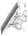
- FIG. 1 is a perspective view from above of a workpiece support 11 according to the invention shown.
- This workpiece support 11 comprises a frame 12, which is provided for receiving bearing elements 14 pointing in the Y-direction. These support elements 14 are guided at least by two support elements 16, in particular in the middle region, which extend in particular in the X direction.
- the support elements 14 form a support panel 17 for one or more workpieces not shown in detail, which are made of a tabular material, which rests on the support elements 14.
- This workpiece support 11 is provided as a separate or traversable pallet which is used in laser processing systems. Such pallets can be loaded and unloaded outside the laser processing system and moved into the laser processing system for processing the workpiece or workpieces. Alternatively, this workpiece support 11 may be provided stationarily in a laser processing machine.
- the preferred tabular base material may be made of various materials and is machined into individual pieces by laser beam cutting.
- FIG. 2 an enlarged side view of a portion of the workpiece support 11 is shown.
- the support element 14, which is movable in the Y direction, has support point tips 18, which are provided for receiving a workpiece, not shown.
- the support element 14 rests with an end portion 21 on a bearing point 19 and is supported on the opposite side by an analogous bearing.
- a link 22 is provided at the end portion 21 of the support element 14, which allows that the support element 14 is displaceable in a sliding movement in and against the Y direction between a reference position 24 in an inactive position 26.
- the support point peaks 18 are in the support area 17.
- the support point points 18 are lowered relative to the support area 17.
- the reference position 24 is also the active position at the same time. Alternatively it can be provided that these two positions are also separated from each other.
- the support point tips 18 of the support elements 14 can also be arranged in an intermediate position, that is to say that the support point tips 18 serve to receive the workpiece but lie adjacent or in an intermediate position with the support point tips 18 of the support elements 14 in a reference position 24.
- the support element 14 is about a displacement device 28, which is described in detail in Figure 5 below and in FIG. 1 is shown only partially positioned in the reference position 24 and the inactive position 26.
- the displacement device 28, which is positioned, for example, below the support elements 14, is transferred into an engagement position 29, that is, that the displacement device 28 performs a retraction movement in the Z direction.
- an overload protection device 31 arranged on the displacement device 28 engages on a positioning element 32 of the support element 14.
- the positioning element 32 is formed according to the embodiment as a web, pin or flag, which is arranged for example in one piece on the receiving element 14.
- the positioning element 32 can also be inserted into the support element 24, welded, clamped or secured by a further releasable connection or be a recess in the support element 14.
- the overload protection device 31 comprises an adjusting element 34, to which a driver 35 is attached, which acts on the positioning element 32.
- the adjusting element 34 is designed as a lifting cylinder, which is preferably driven by a fluid.
- the adjusting element 34 comprises a piston rod 36, at the free end of the driver 35 is preferably attached interchangeable. In the engaged position 29 is the piston rod 36 of the adjusting element 34 is preferably arranged in a retracted position.
- the driver 35 comprises two driver elements 38, which are arranged at a distance to each other such that when transferring the displacement device 28 in an engaged position 29, the positioning element 32 is located between the two driver elements 38 and engages. If the support element 14 is provided in an inactive position 26, for example, a left edge of the positioning element 32 rests against the left drive element 38. If the support element 14 is provided in a reference position 24, a right edge of the positioning element 32 bears against the right-hand driver element 38.
- the displacement device 28 can transfer the bearing element or elements 14 into a reference position 24 by means of a displacement movement in the direction opposite to the Y direction. This is preferably done independently of the position of the individual support elements 14, which are to be set for a subsequent machining program to provide a same starting point for all support elements 14. This is in FIG. 3 shown.
- each support element 14 can be transferred individually into the position defined for the subsequent machining program solely by the overload protection device 31. If the support element 14 is to be arranged in a reference position 24, the overload protection device 31 remains stopped. If the transfer of the support element 14 in an active position 26 is required, the actuator 34 is driven, whereby the piston rod is extended in the Y direction, as in FIG. 4 is shown, and the support element 14 is positioned via the driver 35 in the inactive position 26 or an intermediate layer between them.
- the overload protection device 31 can control all support elements 14 together, a group of support elements 14 or the support elements individually, so that they occupy the required position for the subsequent machining program.
- the actuator 34 For monitoring and avoiding the overload when transferring the support element 14 from an inactive position 26 to a reference position 24, the actuator 34 is arranged with a retracted piston rod when transferred to the engaged position 29, and the sliding movement takes place against the Y-axis, so that the actuating element 34 is claimed to train.
- the driver 35 acting on the positioning element 32 works against a force cushion in the adjusting element 34, which is defined by the pressure in the storage chamber and the piston surface.
- a pressure regulating valve allows the outflow of the storage volume of the fluid present in the chamber, so that the adjusting force is not increased, preferably reduced and the sliding movement of the adjusting device 29 can be terminated in a reference position or end position, without that an overload occurs.
- the overload protection device 31 By the overload protection device 31, the components involved in the sliding movement of the support elements 14, such as the workpiece support 11 and its components and the displacement device 28 and its components are not damaged.
- the displacement movement of the support elements 14 is preferably monitored by a light barrier 43 or by a laser beam.
- the displacement device 28 according to FIG. 5 includes a plurality of overload protection devices 31, which are arranged spaced from each other. It is provided that a reduced number of overload protection devices 31 is provided relative to the support elements 14. Thus, according to the embodiment, an overload protection device 31 successively actuate three mutually adjacent support elements 14. Thereby, a reduction of the component components can be made possible with an efficient setting.
- a laser beam is emitted or a light barrier 43 is positioned, which monitors a front body edge 41 of the driver 35.
- a light barrier 43 provided, which monitors an end position or retracted position of the carrier 35.
- This monitoring by means of a laser beam or light barrier allows simultaneous monitoring of a plurality of drivers 35.
- the position of each individual driver 35 can be detected by a separately associated sensor.
- the setting of the respective positions of the support elements 14 is preferably carried out outside the laser processing system by the displacement device 28 so that it is independent of a machining of a workpiece in the laser processing machine.
- FIGS. 7 to 9 an alternative embodiment of an overload protection device 31 for the support elements 14 is shown.
- the driver 35 is designed as a pivot lever which is rotatably mounted on the adjusting device 28 about a pivot axis 45.
- One end 46 of the cam 35 designed as a pivot lever is designed as a driver element 38, which engages in a positioning element 32 of the support element 14.
- the positioning element 32 is designed as a recess or depression which has a length such that the driver element 38 of the pivoting arm engages independently of a reference position 24 or inactive position 26 of the support element 14.
- An end 48 of the pivot arm opposite end 48 includes a detent recess 49 which is releasably connected to the actuator 34.
- the actuating element 34 is designed as a magnetic lifting cylinder or as a lifting magnet, which positions a holding element 51 in the latching recess 49 via a piston rod 36 that can be moved in the Z direction.
- a link 52 is provided, which has a curved course.
- the adjusting force for the sliding movement of the support element 14 is set or determines the release force for releasing the locking connection between the driver 35 and the actuator 34.
- FIG. 7 corresponds to the illustration in FIG. 2 in which the displacement device 28 is provided in an engagement position 29. Subsequently, as in FIG. 8 shown, the displacement device 28 move counter to the Y direction, whereby the one or more in an inactive position 26 located support elements 14 are converted into a reference position 24.
- FIG. 9 For example, the positioning of a support element 14 from a reference position 24 to an inactive position 26 is shown.
Landscapes
- Engineering & Computer Science (AREA)
- Physics & Mathematics (AREA)
- Optics & Photonics (AREA)
- Mechanical Engineering (AREA)
- Plasma & Fusion (AREA)
- Manipulator (AREA)
- Constituent Portions Of Griding Lathes, Driving, Sensing And Control (AREA)
Claims (15)
- Porte-pièce permettant de recevoir une pièce à usiner dans une unité d'usinage, notamment dans une unité d'usinage au laser, laquelle usine la pièce à usiner au moyen d'un jet de coupe, le porte-pièce (11) recevant dans un cadre (12) plusieurs éléments d'appui (14) disposés côte à côte, lesquels présentent des pointes de support (18) et forment une zone d'appui (17) pour la pièce ou les pièces à usiner, et avec au moins un mécanisme de déplacement (28) qui positionne dans une position intermédiaire ou position inactive (26) située en-dehors du champ d'action du jet de coupe destiné à l'usinage de la pièce ou des pièces à usiner un élément ou plusieurs éléments d'appui (14) se trouvant en position de travail par rapport au cadre (12), et ce par un mouvement de déplacement des éléments d'appui (14) dans une direction de déplacement dans laquelle s'étend l'élément d'appui (14), caractérisé en ce que- après un premier programme d'usinage permettant l'usinage de la pièce ou des pièces à usiner, un élément ou plusieurs éléments d'appui (14) peuvent être déplacés dans une position de référence (24) ou une position inactive (26) en vue d'un programme d'usinage suivant, et- il est prévu au moins un dispositif de protection contre les surcharges (31) qui s'appuie contre le mécanisme de déplacement (28) et qui saisit et contrôle une force de réglage, laquelle provoque le mouvement de déplacement et agit sur ledit au moins un élément d'appui (14) au début ou au cours du mouvement de déplacement.
- Porte-pièce selon la revendication 1, caractérisé en ce que pour un processus de déplacement ledit au moins un dispositif de protection contre les surcharges (31) est en prise avec le mécanisme de déplacement (28) et avec au moins un élément d'appui (14), et en ce que, dans le cas d'une surcharge apparaissant au début ou au cours du mouvement de déplacement, le mouvement de déplacement produit par le mécanisme de déplacement (28) et transmis audit au moins un élément d'appui (14) peut être découplé par le dispositif de protection contre les surcharges (31).
- Porte-pièce selon la revendication 1, caractérisé en ce que le mouvement de déplacement dudit au moins un élément d'appui (14) est stoppé lorsqu'une surcharge est saisie.
- Porte-pièce selon la revendication 1, caractérisé en ce que le dispositif de protection contre les surcharges (31) comprend un entraîneur (35) s'appuyant contre un élément de positionnement (32) et un élément de réglage (34) pouvant être soumis à une force de réglage.
- Porte-pièce selon la revendication 4, caractérisé en ce que l'élément de réglage (34) se compose d'un cylindre pouvant être soumis à un fluide sous pression.
- Porte-pièce selon la revendication 4 ou 5, caractérisé en ce qu'une tige de piston (36) de l'élément de réglage (34) peut être réglée, pendant un mouvement de déplacement de l'élément ou des éléments d'appui (14), sur une position définie et en ce que la tige de piston (36) travaille, pendant le mouvement de déplacement, contre un volume prédéfini dans la chambre de l'élément de réglage (34) et en ce que de préférence le volume de la chambre de l'élément de réglage (34) peut, en cas de surcharge, être réduit et le mouvement de déplacement interrompu.
- Porte-pièce selon la revendication 4, caractérisé en ce que l'élément de réglage (34) est réalisé sous forme de cylindre à double course, et en ce que de préférence la vitesse d'écoulement du volume de la chambre située dans l'élément de réglage (34) peut être contrôlée par une soupape régulatrice de pression.
- Porte-pièce selon la revendication 1, caractérisé en ce que le dispositif de protection contre les surcharges (31) est fixé sur un mécanisme de déplacement (28) qui peut être déplacé, de préférence par en bas, dans une position d'engrènement (29) par rapport à l'élément de positionnement (32) de l'élément ou des éléments d'appui (14) de sorte qu'un entraîneur (35) du dispositif de protection contre les surcharges (31) et l'élément de positionnement (32) engrènent l'un dans l'autre.
- Porte-pièce selon la revendication 8, caractérisé en ce que l'entraîneur (35) présente deux éléments entraîneurs (38) espacés l'un de l'autre, lesquels sont disposés de préférence à une distance donnée l'un de l'autre, laquelle est déterminée respectivement par les positions finales de l'élément de positionnement (32) d'un élément d'appui (14) donné se trouvant dans une position de référence (24) et dans une position inactive (26), ou en ce qu'il est prévu que, lorsque le mécanisme de déplacement (28) se trouve dans une position d'engrènement (29), une tige de piston (36) de l'élément de réglage (34) se trouve dans une position rentrée.
- Porte-pièce selon la revendication 4, caractérisé en ce que le mouvement de déplacement du mécanisme de déplacement (28) s'effectue dans une direction de déplacement telle qu'une tige de piston (36) de l'élément de réglage (34) est soumise à l'effort de traction et travaille contre un volume de la chambre dans l'élément de réglage (34).
- Porte-pièce selon la revendication 4, caractérisé en ce qu'une position finale de l'entraîneur ou des entraîneurs (35) du dispositif de protection contre les surcharges (31) peut être saisie, après un mouvement de déplacement du mécanisme de déplacement (28), par une barrière lumineuse (43) ou un rayon laser.
- Porte-pièce selon la revendication 4, caractérisé en ce que l'élément de réglage (34) est composé d'un cylindre magnétique, ou en ce que l'élément de réglage (34) est composé d'un ressort tendu, de préférence avec une courbe caractéristique d'élasticité constante, lequel s'appuie contre les entraîneurs (35).
- Porte-pièce selon la revendication 1, caractérisé en ce que le dispositif de protection contre les surcharges (31) présente un élément de réglage (34) qui coopère avec un entraîneur (35) réalisé sous forme de levier pivotant, une extrémité de l'entraîneur (35) s'appuyant contre un élément de positionnent (32) de l'élément ou des éléments d'appui (14) et l'entraîneur (35) étant, de préférence, monté de manière à pouvoir tourner sur un axe de pivotement (45) disposé sur le mécanisme de déplacement (28).
- Porte-pièce selon la revendication 13, caractérisé en ce que l'entraîneur (35) présente, à une extrémité située du côté de l'élément de réglage (34), un évidement d'encliquetage (49) prolongé, de part et d'autre, par une coulisse courbe (52).
- Porte-pièce selon la revendication 13, caractérisé en ce que l'élément de réglage (34) est réalisé sous forme de cylindre magnétique, et en ce que la tige de piston (36) de celui-ci reçoit un élément de retenue (51) qui engrène dans l'évidement d'encliquetage (49) de l'entraîneur (35) et qui, une fois l'assemblage par encliquetage enlevé, peut être déplacé le long de la coulisse (52) adjacente.
Applications Claiming Priority (1)
| Application Number | Priority Date | Filing Date | Title |
|---|---|---|---|
| PCT/EP2007/007325 WO2009024163A1 (fr) | 2007-08-20 | 2007-08-20 | Porte-pièce destiné à recevoir une pièce à usiner, notamment en forme de plaque, dans une installation d'usinage |
Publications (2)
| Publication Number | Publication Date |
|---|---|
| EP2180971A1 EP2180971A1 (fr) | 2010-05-05 |
| EP2180971B1 true EP2180971B1 (fr) | 2012-01-04 |
Family
ID=39262793
Family Applications (1)
| Application Number | Title | Priority Date | Filing Date |
|---|---|---|---|
| EP07801765A Not-in-force EP2180971B1 (fr) | 2007-08-20 | 2007-08-20 | Porte-pièce destiné à recevoir une pièce à usiner, notamment en forme de plaque, dans une installation d'usinage |
Country Status (3)
| Country | Link |
|---|---|
| EP (1) | EP2180971B1 (fr) |
| AT (1) | ATE539838T1 (fr) |
| WO (1) | WO2009024163A1 (fr) |
Families Citing this family (2)
| Publication number | Priority date | Publication date | Assignee | Title |
|---|---|---|---|---|
| US11332314B2 (en) | 2018-01-15 | 2022-05-17 | Bobst Mex Sa | Conveyor belt assembly |
| DE102020107256A1 (de) | 2020-03-17 | 2021-09-23 | Trumpf Werkzeugmaschinen Gmbh + Co. Kg | Verfahren und Vorrichtung zur Bestimmung eines Ist-Zustands von Auflageleisten einer Werkstückauflage sowie Werkzeugmaschine mit einer derartigen Vorrichtung |
Family Cites Families (5)
| Publication number | Priority date | Publication date | Assignee | Title |
|---|---|---|---|---|
| DE3803918A1 (de) | 1988-02-09 | 1989-08-17 | Interatom | Auflage mit beweglichen lamellen zur halterung von werkstuecken bei laserschneidgeraeten |
| DE19615928C1 (de) * | 1996-04-22 | 1998-02-12 | Fraunhofer Ges Forschung | Überlastungsschutzeinrichtung für mechanische Pressen |
| DE19709746C1 (de) * | 1997-03-10 | 1998-11-19 | Fraunhofer Ges Forschung | Ventil |
| JP2001170790A (ja) | 1999-12-10 | 2001-06-26 | Mitsubishi Electric Corp | 被加工物支持台 |
| JP4254198B2 (ja) * | 2002-10-25 | 2009-04-15 | 株式会社ジェイテクト | ワーク支持装置及び同装置のための着座機構 |
-
2007
- 2007-08-20 WO PCT/EP2007/007325 patent/WO2009024163A1/fr not_active Ceased
- 2007-08-20 AT AT07801765T patent/ATE539838T1/de active
- 2007-08-20 EP EP07801765A patent/EP2180971B1/fr not_active Not-in-force
Also Published As
| Publication number | Publication date |
|---|---|
| EP2180971A1 (fr) | 2010-05-05 |
| WO2009024163A1 (fr) | 2009-02-26 |
| ATE539838T1 (de) | 2012-01-15 |
Similar Documents
| Publication | Publication Date | Title |
|---|---|---|
| EP0418779B1 (fr) | Méthode pour manufacture de pièces d'oeuvre par découpage, en particulier dans un outil à contre découpage à précision | |
| EP2734462B1 (fr) | Dispositif et procédé permettant d'arrêter et/ou d'orienter des produits transportés sur un convoyeur, et convoyeur | |
| EP2210681B1 (fr) | Presse à plier dotée d'une barre de pressage en plusieurs parties | |
| EP3219429B1 (fr) | Machine-outil équipée d'un dispositif d'estampage et d'un dispositif d'usinage laser et procédé d'usinage de pièces à l'aide d'une telle machine-outil | |
| AT519203B1 (de) | Hinteranschlag für eine Biegemaschine | |
| DE102016111616B4 (de) | Vorrichtung und Verfahren zum Setzen eines Fügeelements an einem Werkstück oder zum Durchsetzfügen des Werkstücks | |
| DE19853366B4 (de) | Vorrichtung und Verfahren zum Umformen | |
| EP0857544B1 (fr) | Dispositif de serrage pour pièces à travailler | |
| EP2029314B1 (fr) | Porte-pièce destiné à recevoir une pièce en particulier en forme de plaque dans une unité d'usinage comprenant des éléments de support mobiles présentant des pointes d'appui | |
| EP2345495B1 (fr) | Dispositif de serrage d'une pièce ou d'un outil sur une broche de travail | |
| DE102004062048A1 (de) | Vorschubvorrichtung für plattenförmige Werkstücke | |
| EP2522464B1 (fr) | Mordache et procédé de fabrication d'un emmanchement par pressage | |
| EP3370890B1 (fr) | Dispositif de réglage d'un cylindre de refoulement d'une cage refouleuse | |
| DE102010028678B4 (de) | Werkzeughalterung, Werkzeugmaschine mit einer derartigen Werkzeughalterung sowie Verfahren zum Festlegen eines Bearbeitungswerkzeuges an einer Werkzeughalterung einer Werkzeugmaschine | |
| EP1652615B1 (fr) | Dispositif de fixation pour une installation de soudage laser avec des supports activés chacun par un fluide hydraulique sous pression | |
| WO2009024163A1 (fr) | Porte-pièce destiné à recevoir une pièce à usiner, notamment en forme de plaque, dans une installation d'usinage | |
| WO2007134630A1 (fr) | Procédé, dispositif de réglage et élément de support pour régler un porte-pièce destiné à recevoir une pièce en forme de plaque | |
| WO2005051602A1 (fr) | Dispositif de serrage à levier coudé | |
| EP3302843B1 (fr) | Outil de pliage pour presse plieuse | |
| DE102011001672B4 (de) | Vorrichtung zum Umformen von Werkstücken | |
| WO2009024166A1 (fr) | Procédé de rétablissement de la mobilité d'éléments supports dans un porte-pièce | |
| DE102011001955B4 (de) | Presswerkzeug mit einem Zusatzwerkzeug und Verfahren zur Betätigung eines Zusatzwerkzeugs eines Presswerkzeugs | |
| EP3052265B1 (fr) | Installation d'ébavurage thermique comprenant un ensemble porteur mobile | |
| EP1410858B1 (fr) | Presse ou poinçonneuse | |
| DE9217181U1 (de) | Vorrichtung zum Verbinden von zwei oder mehreren aufeinanderliegenden, flächigen Blechteilen durch Fliesverformung |
Legal Events
| Date | Code | Title | Description |
|---|---|---|---|
| PUAI | Public reference made under article 153(3) epc to a published international application that has entered the european phase |
Free format text: ORIGINAL CODE: 0009012 |
|
| 17P | Request for examination filed |
Effective date: 20100322 |
|
| AK | Designated contracting states |
Kind code of ref document: A1 Designated state(s): AT BE BG CH CY CZ DE DK EE ES FI FR GB GR HU IE IS IT LI LT LU LV MC MT NL PL PT RO SE SI SK TR |
|
| AX | Request for extension of the european patent |
Extension state: AL BA HR MK RS |
|
| DAX | Request for extension of the european patent (deleted) | ||
| 17Q | First examination report despatched |
Effective date: 20101124 |
|
| GRAP | Despatch of communication of intention to grant a patent |
Free format text: ORIGINAL CODE: EPIDOSNIGR1 |
|
| GRAS | Grant fee paid |
Free format text: ORIGINAL CODE: EPIDOSNIGR3 |
|
| GRAA | (expected) grant |
Free format text: ORIGINAL CODE: 0009210 |
|
| AK | Designated contracting states |
Kind code of ref document: B1 Designated state(s): AT BE BG CH CY CZ DE DK EE ES FI FR GB GR HU IE IS IT LI LT LU LV MC MT NL PL PT RO SE SI SK TR |
|
| REG | Reference to a national code |
Ref country code: GB Ref legal event code: FG4D Free format text: NOT ENGLISH |
|
| REG | Reference to a national code |
Ref country code: CH Ref legal event code: EP |
|
| REG | Reference to a national code |
Ref country code: AT Ref legal event code: REF Ref document number: 539838 Country of ref document: AT Kind code of ref document: T Effective date: 20120115 |
|
| REG | Reference to a national code |
Ref country code: IE Ref legal event code: FG4D |
|
| REG | Reference to a national code |
Ref country code: DE Ref legal event code: R096 Ref document number: 502007009003 Country of ref document: DE Effective date: 20120308 |
|
| REG | Reference to a national code |
Ref country code: NL Ref legal event code: VDEP Effective date: 20120104 |
|
| PG25 | Lapsed in a contracting state [announced via postgrant information from national office to epo] |
Ref country code: SI Free format text: LAPSE BECAUSE OF FAILURE TO SUBMIT A TRANSLATION OF THE DESCRIPTION OR TO PAY THE FEE WITHIN THE PRESCRIBED TIME-LIMIT Effective date: 20120104 |
|
| LTIE | Lt: invalidation of european patent or patent extension |
Effective date: 20120104 |
|
| PG25 | Lapsed in a contracting state [announced via postgrant information from national office to epo] |
Ref country code: LT Free format text: LAPSE BECAUSE OF FAILURE TO SUBMIT A TRANSLATION OF THE DESCRIPTION OR TO PAY THE FEE WITHIN THE PRESCRIBED TIME-LIMIT Effective date: 20120104 Ref country code: NL Free format text: LAPSE BECAUSE OF FAILURE TO SUBMIT A TRANSLATION OF THE DESCRIPTION OR TO PAY THE FEE WITHIN THE PRESCRIBED TIME-LIMIT Effective date: 20120104 Ref country code: IS Free format text: LAPSE BECAUSE OF FAILURE TO SUBMIT A TRANSLATION OF THE DESCRIPTION OR TO PAY THE FEE WITHIN THE PRESCRIBED TIME-LIMIT Effective date: 20120504 Ref country code: BG Free format text: LAPSE BECAUSE OF FAILURE TO SUBMIT A TRANSLATION OF THE DESCRIPTION OR TO PAY THE FEE WITHIN THE PRESCRIBED TIME-LIMIT Effective date: 20120404 |
|
| REG | Reference to a national code |
Ref country code: IE Ref legal event code: FD4D |
|
| PG25 | Lapsed in a contracting state [announced via postgrant information from national office to epo] |
Ref country code: LV Free format text: LAPSE BECAUSE OF FAILURE TO SUBMIT A TRANSLATION OF THE DESCRIPTION OR TO PAY THE FEE WITHIN THE PRESCRIBED TIME-LIMIT Effective date: 20120104 Ref country code: PT Free format text: LAPSE BECAUSE OF FAILURE TO SUBMIT A TRANSLATION OF THE DESCRIPTION OR TO PAY THE FEE WITHIN THE PRESCRIBED TIME-LIMIT Effective date: 20120504 Ref country code: FI Free format text: LAPSE BECAUSE OF FAILURE TO SUBMIT A TRANSLATION OF THE DESCRIPTION OR TO PAY THE FEE WITHIN THE PRESCRIBED TIME-LIMIT Effective date: 20120104 Ref country code: GR Free format text: LAPSE BECAUSE OF FAILURE TO SUBMIT A TRANSLATION OF THE DESCRIPTION OR TO PAY THE FEE WITHIN THE PRESCRIBED TIME-LIMIT Effective date: 20120405 Ref country code: PL Free format text: LAPSE BECAUSE OF FAILURE TO SUBMIT A TRANSLATION OF THE DESCRIPTION OR TO PAY THE FEE WITHIN THE PRESCRIBED TIME-LIMIT Effective date: 20120104 |
|
| PG25 | Lapsed in a contracting state [announced via postgrant information from national office to epo] |
Ref country code: CY Free format text: LAPSE BECAUSE OF FAILURE TO SUBMIT A TRANSLATION OF THE DESCRIPTION OR TO PAY THE FEE WITHIN THE PRESCRIBED TIME-LIMIT Effective date: 20120104 |
|
| PG25 | Lapsed in a contracting state [announced via postgrant information from national office to epo] |
Ref country code: IE Free format text: LAPSE BECAUSE OF FAILURE TO SUBMIT A TRANSLATION OF THE DESCRIPTION OR TO PAY THE FEE WITHIN THE PRESCRIBED TIME-LIMIT Effective date: 20120104 Ref country code: RO Free format text: LAPSE BECAUSE OF FAILURE TO SUBMIT A TRANSLATION OF THE DESCRIPTION OR TO PAY THE FEE WITHIN THE PRESCRIBED TIME-LIMIT Effective date: 20120104 Ref country code: SE Free format text: LAPSE BECAUSE OF FAILURE TO SUBMIT A TRANSLATION OF THE DESCRIPTION OR TO PAY THE FEE WITHIN THE PRESCRIBED TIME-LIMIT Effective date: 20120104 Ref country code: DK Free format text: LAPSE BECAUSE OF FAILURE TO SUBMIT A TRANSLATION OF THE DESCRIPTION OR TO PAY THE FEE WITHIN THE PRESCRIBED TIME-LIMIT Effective date: 20120104 Ref country code: EE Free format text: LAPSE BECAUSE OF FAILURE TO SUBMIT A TRANSLATION OF THE DESCRIPTION OR TO PAY THE FEE WITHIN THE PRESCRIBED TIME-LIMIT Effective date: 20120104 Ref country code: CZ Free format text: LAPSE BECAUSE OF FAILURE TO SUBMIT A TRANSLATION OF THE DESCRIPTION OR TO PAY THE FEE WITHIN THE PRESCRIBED TIME-LIMIT Effective date: 20120104 |
|
| PLBE | No opposition filed within time limit |
Free format text: ORIGINAL CODE: 0009261 |
|
| STAA | Information on the status of an ep patent application or granted ep patent |
Free format text: STATUS: NO OPPOSITION FILED WITHIN TIME LIMIT |
|
| PG25 | Lapsed in a contracting state [announced via postgrant information from national office to epo] |
Ref country code: SK Free format text: LAPSE BECAUSE OF FAILURE TO SUBMIT A TRANSLATION OF THE DESCRIPTION OR TO PAY THE FEE WITHIN THE PRESCRIBED TIME-LIMIT Effective date: 20120104 |
|
| 26N | No opposition filed |
Effective date: 20121005 |
|
| REG | Reference to a national code |
Ref country code: DE Ref legal event code: R097 Ref document number: 502007009003 Country of ref document: DE Effective date: 20121005 |
|
| BERE | Be: lapsed |
Owner name: TRUMPF WERKZEUGMASCHINEN G.M.B.H. + CO. KG Effective date: 20120831 |
|
| PG25 | Lapsed in a contracting state [announced via postgrant information from national office to epo] |
Ref country code: MC Free format text: LAPSE BECAUSE OF NON-PAYMENT OF DUE FEES Effective date: 20120831 |
|
| GBPC | Gb: european patent ceased through non-payment of renewal fee |
Effective date: 20120820 |
|
| PG25 | Lapsed in a contracting state [announced via postgrant information from national office to epo] |
Ref country code: ES Free format text: LAPSE BECAUSE OF FAILURE TO SUBMIT A TRANSLATION OF THE DESCRIPTION OR TO PAY THE FEE WITHIN THE PRESCRIBED TIME-LIMIT Effective date: 20120415 |
|
| REG | Reference to a national code |
Ref country code: FR Ref legal event code: ST Effective date: 20130430 |
|
| PG25 | Lapsed in a contracting state [announced via postgrant information from national office to epo] |
Ref country code: BE Free format text: LAPSE BECAUSE OF NON-PAYMENT OF DUE FEES Effective date: 20120831 |
|
| PG25 | Lapsed in a contracting state [announced via postgrant information from national office to epo] |
Ref country code: GB Free format text: LAPSE BECAUSE OF NON-PAYMENT OF DUE FEES Effective date: 20120820 |
|
| PG25 | Lapsed in a contracting state [announced via postgrant information from national office to epo] |
Ref country code: FR Free format text: LAPSE BECAUSE OF NON-PAYMENT OF DUE FEES Effective date: 20120831 |
|
| REG | Reference to a national code |
Ref country code: AT Ref legal event code: MM01 Ref document number: 539838 Country of ref document: AT Kind code of ref document: T Effective date: 20120831 |
|
| PG25 | Lapsed in a contracting state [announced via postgrant information from national office to epo] |
Ref country code: AT Free format text: LAPSE BECAUSE OF NON-PAYMENT OF DUE FEES Effective date: 20120831 |
|
| PG25 | Lapsed in a contracting state [announced via postgrant information from national office to epo] |
Ref country code: MT Free format text: LAPSE BECAUSE OF FAILURE TO SUBMIT A TRANSLATION OF THE DESCRIPTION OR TO PAY THE FEE WITHIN THE PRESCRIBED TIME-LIMIT Effective date: 20120104 |
|
| PG25 | Lapsed in a contracting state [announced via postgrant information from national office to epo] |
Ref country code: TR Free format text: LAPSE BECAUSE OF FAILURE TO SUBMIT A TRANSLATION OF THE DESCRIPTION OR TO PAY THE FEE WITHIN THE PRESCRIBED TIME-LIMIT Effective date: 20120104 |
|
| PG25 | Lapsed in a contracting state [announced via postgrant information from national office to epo] |
Ref country code: LU Free format text: LAPSE BECAUSE OF NON-PAYMENT OF DUE FEES Effective date: 20120820 |
|
| PG25 | Lapsed in a contracting state [announced via postgrant information from national office to epo] |
Ref country code: HU Free format text: LAPSE BECAUSE OF FAILURE TO SUBMIT A TRANSLATION OF THE DESCRIPTION OR TO PAY THE FEE WITHIN THE PRESCRIBED TIME-LIMIT Effective date: 20070820 |
|
| PGFP | Annual fee paid to national office [announced via postgrant information from national office to epo] |
Ref country code: DE Payment date: 20190822 Year of fee payment: 13 Ref country code: IT Payment date: 20190829 Year of fee payment: 13 |
|
| PGFP | Annual fee paid to national office [announced via postgrant information from national office to epo] |
Ref country code: CH Payment date: 20190821 Year of fee payment: 13 |
|
| REG | Reference to a national code |
Ref country code: DE Ref legal event code: R119 Ref document number: 502007009003 Country of ref document: DE |
|
| REG | Reference to a national code |
Ref country code: CH Ref legal event code: PL |
|
| PG25 | Lapsed in a contracting state [announced via postgrant information from national office to epo] |
Ref country code: CH Free format text: LAPSE BECAUSE OF NON-PAYMENT OF DUE FEES Effective date: 20200831 Ref country code: LI Free format text: LAPSE BECAUSE OF NON-PAYMENT OF DUE FEES Effective date: 20200831 |
|
| PG25 | Lapsed in a contracting state [announced via postgrant information from national office to epo] |
Ref country code: IT Free format text: LAPSE BECAUSE OF NON-PAYMENT OF DUE FEES Effective date: 20200820 Ref country code: DE Free format text: LAPSE BECAUSE OF NON-PAYMENT OF DUE FEES Effective date: 20210302 |