EP2180976B1 - Moteur de broche - Google Patents
Moteur de broche Download PDFInfo
- Publication number
- EP2180976B1 EP2180976B1 EP08784829A EP08784829A EP2180976B1 EP 2180976 B1 EP2180976 B1 EP 2180976B1 EP 08784829 A EP08784829 A EP 08784829A EP 08784829 A EP08784829 A EP 08784829A EP 2180976 B1 EP2180976 B1 EP 2180976B1
- Authority
- EP
- European Patent Office
- Prior art keywords
- spindle
- piston rod
- motor according
- threaded
- threaded spindle
- Prior art date
- Legal status (The legal status is an assumption and is not a legal conclusion. Google has not performed a legal analysis and makes no representation as to the accuracy of the status listed.)
- Active
Links
Images


Classifications
-
- B—PERFORMING OPERATIONS; TRANSPORTING
- B23—MACHINE TOOLS; METAL-WORKING NOT OTHERWISE PROVIDED FOR
- B23Q—DETAILS, COMPONENTS, OR ACCESSORIES FOR MACHINE TOOLS, e.g. ARRANGEMENTS FOR COPYING OR CONTROLLING; MACHINE TOOLS IN GENERAL CHARACTERISED BY THE CONSTRUCTION OF PARTICULAR DETAILS OR COMPONENTS; COMBINATIONS OR ASSOCIATIONS OF METAL-WORKING MACHINES, NOT DIRECTED TO A PARTICULAR RESULT
- B23Q5/00—Driving or feeding mechanisms; Control arrangements therefor
- B23Q5/22—Feeding members carrying tools or work
- B23Q5/34—Feeding other members supporting tools or work, e.g. saddles, tool-slides, through mechanical transmission
- B23Q5/38—Feeding other members supporting tools or work, e.g. saddles, tool-slides, through mechanical transmission feeding continuously
- B23Q5/40—Feeding other members supporting tools or work, e.g. saddles, tool-slides, through mechanical transmission feeding continuously by feed shaft, e.g. lead screw
-
- B—PERFORMING OPERATIONS; TRANSPORTING
- B23—MACHINE TOOLS; METAL-WORKING NOT OTHERWISE PROVIDED FOR
- B23Q—DETAILS, COMPONENTS, OR ACCESSORIES FOR MACHINE TOOLS, e.g. ARRANGEMENTS FOR COPYING OR CONTROLLING; MACHINE TOOLS IN GENERAL CHARACTERISED BY THE CONSTRUCTION OF PARTICULAR DETAILS OR COMPONENTS; COMBINATIONS OR ASSOCIATIONS OF METAL-WORKING MACHINES, NOT DIRECTED TO A PARTICULAR RESULT
- B23Q11/00—Accessories fitted to machine tools for keeping tools or parts of the machine in good working condition or for cooling work; Safety devices specially combined with or arranged in, or specially adapted for use in connection with, machine tools
- B23Q11/12—Arrangements for cooling or lubricating parts of the machine
- B23Q11/121—Arrangements for cooling or lubricating parts of the machine with lubricating effect for reducing friction
- B23Q11/125—Arrangements for cooling or lubricating parts of the machine with lubricating effect for reducing friction for lubricating ball screw systems
-
- F—MECHANICAL ENGINEERING; LIGHTING; HEATING; WEAPONS; BLASTING
- F16—ENGINEERING ELEMENTS AND UNITS; GENERAL MEASURES FOR PRODUCING AND MAINTAINING EFFECTIVE FUNCTIONING OF MACHINES OR INSTALLATIONS; THERMAL INSULATION IN GENERAL
- F16H—GEARING
- F16H25/00—Gearings comprising primarily only cams, cam-followers and screw-and-nut mechanisms
- F16H25/18—Gearings comprising primarily only cams, cam-followers and screw-and-nut mechanisms for conveying or interconverting oscillating or reciprocating motions
- F16H25/20—Screw mechanisms
- F16H25/24—Elements essential to such mechanisms, e.g. screws, nuts
-
- F—MECHANICAL ENGINEERING; LIGHTING; HEATING; WEAPONS; BLASTING
- F16—ENGINEERING ELEMENTS AND UNITS; GENERAL MEASURES FOR PRODUCING AND MAINTAINING EFFECTIVE FUNCTIONING OF MACHINES OR INSTALLATIONS; THERMAL INSULATION IN GENERAL
- F16H—GEARING
- F16H57/00—General details of gearing
- F16H57/04—Features relating to lubrication or cooling or heating
- F16H57/0434—Features relating to lubrication or cooling or heating relating to lubrication supply, e.g. pumps; Pressure control
-
- F—MECHANICAL ENGINEERING; LIGHTING; HEATING; WEAPONS; BLASTING
- F16—ENGINEERING ELEMENTS AND UNITS; GENERAL MEASURES FOR PRODUCING AND MAINTAINING EFFECTIVE FUNCTIONING OF MACHINES OR INSTALLATIONS; THERMAL INSULATION IN GENERAL
- F16H—GEARING
- F16H57/00—General details of gearing
- F16H57/04—Features relating to lubrication or cooling or heating
- F16H57/048—Type of gearings to be lubricated, cooled or heated
- F16H57/0497—Screw mechanisms
-
- F—MECHANICAL ENGINEERING; LIGHTING; HEATING; WEAPONS; BLASTING
- F16—ENGINEERING ELEMENTS AND UNITS; GENERAL MEASURES FOR PRODUCING AND MAINTAINING EFFECTIVE FUNCTIONING OF MACHINES OR INSTALLATIONS; THERMAL INSULATION IN GENERAL
- F16H—GEARING
- F16H25/00—Gearings comprising primarily only cams, cam-followers and screw-and-nut mechanisms
- F16H25/18—Gearings comprising primarily only cams, cam-followers and screw-and-nut mechanisms for conveying or interconverting oscillating or reciprocating motions
- F16H25/20—Screw mechanisms
- F16H2025/2062—Arrangements for driving the actuator
- F16H2025/2075—Coaxial drive motors
-
- F—MECHANICAL ENGINEERING; LIGHTING; HEATING; WEAPONS; BLASTING
- F16—ENGINEERING ELEMENTS AND UNITS; GENERAL MEASURES FOR PRODUCING AND MAINTAINING EFFECTIVE FUNCTIONING OF MACHINES OR INSTALLATIONS; THERMAL INSULATION IN GENERAL
- F16H—GEARING
- F16H25/00—Gearings comprising primarily only cams, cam-followers and screw-and-nut mechanisms
- F16H25/18—Gearings comprising primarily only cams, cam-followers and screw-and-nut mechanisms for conveying or interconverting oscillating or reciprocating motions
- F16H25/20—Screw mechanisms
- F16H25/24—Elements essential to such mechanisms, e.g. screws, nuts
- F16H2025/2436—Intermediate screw supports for reducing unsupported length of screw shaft
-
- F—MECHANICAL ENGINEERING; LIGHTING; HEATING; WEAPONS; BLASTING
- F16—ENGINEERING ELEMENTS AND UNITS; GENERAL MEASURES FOR PRODUCING AND MAINTAINING EFFECTIVE FUNCTIONING OF MACHINES OR INSTALLATIONS; THERMAL INSULATION IN GENERAL
- F16H—GEARING
- F16H57/00—General details of gearing
- F16H57/04—Features relating to lubrication or cooling or heating
- F16H57/042—Guidance of lubricant
- F16H57/043—Guidance of lubricant within rotary parts, e.g. axial channels or radial openings in shafts
-
- F—MECHANICAL ENGINEERING; LIGHTING; HEATING; WEAPONS; BLASTING
- F16—ENGINEERING ELEMENTS AND UNITS; GENERAL MEASURES FOR PRODUCING AND MAINTAINING EFFECTIVE FUNCTIONING OF MACHINES OR INSTALLATIONS; THERMAL INSULATION IN GENERAL
- F16H—GEARING
- F16H57/00—General details of gearing
- F16H57/04—Features relating to lubrication or cooling or heating
- F16H57/0467—Elements of gearings to be lubricated, cooled or heated
- F16H57/0469—Bearings or seals
- F16H57/0471—Bearing
Definitions
- the invention relates to a spindle motor.
- high-pressure seals from the field of hydraulics are known, such as a PTFE U-ring seal with a V-spring made of steel, there designated with MA47.
- another high-pressure seal is known, such as the product WCP21, which is a radial shaft seal with a PTFE sealing lip and a Elastomervorspannfusion clamped between two metal cages.
- the invention is therefore based on the object to extend the service life in a spindle motor.
- the object is achieved in the spindle motor according to the features specified in claim 1.
- the spindle motor comprises an electric motor with a rotor which is connected to a threaded spindle, the thread of which is in engagement with a thread of a spindle nut connected to a piston rod, wherein the spindle nut is guided axially with piston rod
- a guide member is connected to the spindle nut and the piston rod for axial guidance
- a support component for the threaded spindle is provided.
- the advantage here is that a large stroke length can be realized because a support component of the otherwise free end of the threaded spindle is executable.
- the threaded spindle is mounted via a bearing which is arranged in a housing part between the motor and the spindle housing portion. It is also stored in the spindle nut. With a large axial length of the threaded spindle, this is additionally supported by the support component at its other end remote from the first end axial end, wherein the bearing is provided at the first end, ie the motor side.
- the axial end of the threaded spindle mounted by means of the support component is thus the end of the threaded spindle facing away from the motor.
- very high speeds in any position of the piston rod are possible.
- the support component is pressed into the piston rod.
- the support component supports the axial end of the threaded spindle which is turned away from the motor, the piston rod is driven out to a critical value, and when the critical value is exceeded, the threaded spindle is supported only by the spindle nut and a bearing.
- the advantage here is that with very far out driving even lower friction losses occur and still an efficient storage is guaranteed.
- the support component is advantageous because the threaded spindle is located near the camp and thus a large part of the threaded spindle would protrude and cause a deflection by its own weight and would prevent high speeds.
- the support component made of PTFE and / or Teflon is executed.
- the advantage here is that only small friction losses occur because the threaded spindle of a hard material, such as metal, steel or the like, can be manufactured.
- the oil bath is provided in the interior of the spindle motor, in particular in the spindle region on the output side of the electric motor.
- a seal is provided between the space area of the electric motor and the space area in which the spindle nut is arranged.
- at least one high-pressure seal is used for sealing, in particular between spindle area and electric motor and / or between spindle area and surroundings.
- an oil pump is also integrally provided in the threaded spindle, which promotes the oil to the high-pressure seal axially through the threaded spindle through.
- the advantage here is that a continuous operation without interruption for grease lubrication and the like is possible.
- a particularly compact design is possible and low friction losses are foreseeable.
- a lifetime lubrication is possible.
- the heat dissipation is improved because the heat generated inside is better spread and thus the entire surface for heat dissipation locally limited friction sources and thus heat sources is available.
- the seal is arranged axially between a bearing of the threaded spindle and a coupling connecting the rotor shaft and the threaded spindle.
- the coupling is an axially pluggable coupling.
- the seal is designed as a shaft seal, which has its seat in a housing part, which also has a seat for receiving the bearing of the threaded spindle, wherein the running surface of the shaft sealing ring is provided on the threaded spindle.
- the threaded spindle has a shoulder for receiving axial forces.
- the advantage here is that the electric motor remains protected from axial forces.
- the axially pluggable coupling is used for connecting, since during normal operation, the coupling is protected against axial forces. If now engine and spindle to be separated, axial force is applied when lifting the engine and thus the clutch is disconnected.
- the shoulder is supported on the inner ring of the bearing provided for the threaded spindle bearing.
- the piston rod is the output side of a lubricant-operated seal assembly sealed to the output side housing part.
- the sealing arrangement comprises at least one scraper, an O-ring and / or a groove seal.
- the advantage here is that lubricant-operated, in particular oil-operated sealing elements can be used, which ensure even at an overpressure of 2 bar or more tightness.
- a support component is connected in the piston rod, in particular pressed.
- the support component is designed as a substantially cylindrical recess, wherein an insertion bevel is provided for the threading of the threaded spindle at its open end.
- the advantage here is that low friction occurs, especially when using PTFE material, especially Teflon, for the support component.
- the threaded spindle is made of metal, especially steel.
- the threaded spindle comprises at least one lubricant channel, in particular a composite of at least one lubricant bore.
- oil is passable through the threaded spindle and can be deflected at a location where elements to be lubricated are arranged.
- the threaded spindle comprises at its end facing away from the motor, a valve which is connected to the lubricant channel.
- valve is between an inlet opening and the lubricant channel, in particular within the threaded spindle.
- the valve comprises at least one ball pressed by a spring against an opening.
- the lubricant channel opens at least with its second end in the region of the seal that lubricant is supplied to the seal.
- lubricant channel opens at least with its second end between the seal and the bearing.
- the threaded spindle with the rotor is mounted in a housing part of the electric motor.
- a guide member for axial guidance with the spindle nut and the piston rod is connected.
- the advantage here is that the guide member takes over the function of the connection of the spindle nut and piston rod and the function of the guide in the axial direction.
- the guide member is axially guided in the housing part via sliding blocks, in particular sliding blocks, which are arranged axially movable in a groove of the housing part.
- the rotor is connected without play to the threaded spindle, in particular by means of a screw connection together with a clamping connection.
- the piston rod is sealed by means of a seal, in particular rod seal, in particular scraper, against a housing part.
- a seal in particular rod seal, in particular scraper
- an elastic element in particular an O-ring, is arranged in the region of the axial end positions, ie stops, of the guide part for receiving kinetic energy when hitting the end position.
- the guide member is connected to the piston rod by means of clamping connection.
- the clamping connection comprises clamping means, with which the guide member is deformable such that the piston rod can be clamped.
- the clamping means are provided tangentially aligned, in particular for securing the rotation of the piston rod against the guide member.
- three sliding blocks are arranged on the circumference.
- the advantage here is that only a small number of sliding blocks is necessary.
- an adjusting ring is provided, wherein by means of a clamping elements of the inner ring of a bearing of the engine is executable.
- by means of further screw generating a pressure force for the clamping connection between the threaded spindle and rotor executable is provided.
- the rotor has one or more axial slots in an axial end region.
- the advantage here is that only small pressure forces for clamping are necessary.
- a positive connection between the guide member and the piston rod is provided by means of clamping means.
- clamping means are dowel pins, so clamping sleeves used, which are inserted into cylindrical holes.
- a flattening is provided on the piston rod, that the dowel pins are surrounded touching and cling to this flattening surface due to their due to elastic deformation contact pressure.
- the flattening is carried out as part of a surface of an imaginary cylinder.
- the threaded spindle has at its one end region a pin for centering.
- the centering part is provided for centering the housing part on the motor flange.
- the centering part is provided for receiving an elastic element.
- the piston rod is made smooth on its surface provided for the environment.
- the rotor comprises permanent magnets, in particular the spindle motor is driven by the synchronous motor principle.
- the advantage here is that high forces can be generated. Further advantages emerge from the subclaims.
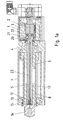
- the motor housing 1 of the electric motor comprising rotor shaft 2 and stator 3, is tightly connected to the housing parts 4, 7 and 15 of the spindle motor.
- Preference meadow is at each connection interface of the housing parts an O-ring miteinpel to ensure tightness against overpressure, of more than, for example, 2 bar.
- the housing part 4 receives the bearing 18, via which the threaded spindle 5 is mounted. This is connected via an axially pluggable coupling with the rotor shaft 2.
- the coupling has a claw part 20 and a claw part 22, between which a plastic star 21 is arranged. Preferably, this shaft coupling is free of play.
- the interior is filled with oil.
- the piston rod 14 by means of guide ring 9, sealing ring 10 and wiper 11 sealed against the environment.
- the seals are chosen such that they ensure against overpressure of more than 2 bar tightness.
- the threaded spindle has a shoulder 16 which dissipates axial forces to the bearing 18th
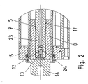
- a support component 8 is provided from Teflon, which has a cylindrical bore for Receiving the threaded spindle 5 and at its open end has a widening in the FIGS. 1 and 2 can be seen as an insertion bevel 17.
- the support component 8 is press-connected in the piston rod 14 and loses contact with the threaded spindle 5 when the piston rod is driven far out. In this case, however, the spindle nut is moved far and takes over the supporting function.
- Lubricant is provided around the threaded spindle 5, in particular oil.
- the described oil pump is effective when the piston rod pointing downwards so in the direction of gravity. However, when facing up, the oil automatically flows to the bearing 18 and the seal 19.
- the ball 12 is displaced by reducing the local overpressure by a spring element 24 into its initial position.
- the oil bath improves the heat dissipation, since the heat is better spread and thus the housing parts are heated more uniformly from the inside of the spindle motor area.
- a high pressure seal is preferably used, such as a WCP21 or MA47.
Landscapes
- Engineering & Computer Science (AREA)
- General Engineering & Computer Science (AREA)
- Mechanical Engineering (AREA)
- Connection Of Motors, Electrical Generators, Mechanical Devices, And The Like (AREA)
Claims (15)
- Moteur de broche,
comprenant un moteur électrique avec un rotor qui est relié à une broche filetée (5) dont le filetage est en prise avec un filetage d'un écrou de broche (6) relié à une tige de piston (14),
l'écrou de broche (6) avec tige de piston (14) étant guidé axialement dans une partie de carter (7),
une pièce de guidage (25) étant reliée à l'écrou de broche (6) et la tige de piston (14) pour le guidage axial,
caractérisé en ce que
un composant de soutien (8) pour la broche filetée (5), relié à la tige de piston (14), est prévu dans la tige de piston (14) de telle manière que(i) tant que la tige de piston (14) est sortie jusqu'à une valeur critique, l'écrou de broche (6), un palier (18) et le composant de soutien (8) supportent la broche filetée (5), le composant de soutien (8) supportant en l'occurrence l'extrémité axiale de la broche filetée (5) éloignée du moteur,(ii) et qu'en cas de dépassement de la valeur critique, donc en cas de sortie de la tige de piston (14) au-delà de la valeur critique, la broche filetée (5) n'est plus supportée que par l'écrou de broche (6) et le palier (18). - Moteur de broche selon une des revendications précédentes,
caractérisé en ce que
le composant de soutien (8) est enfoncé dans la tige de piston (14). - Moteur de broche selon une des revendications précédentes,
caractérisé en ce que
le composant de soutien (8) est réalisé sous la forme d'un évidement essentiellement cylindrique, un chanfrein d'introduction (17) étant prévu dans sa zone d'extrémité ouverte pour l'insertion de la broche filetée (5). - Moteur de broche selon une des revendications précédentes,
caractérisé en ce que
le composant de soutien (8) est réalisé en PTFE et/ou en téflon. - Moteur de broche selon une des revendications précédentes,
caractérisé en ce que
le bain d'huile est prévu à l'intérieur du moteur de broche, en particulier dans la zone de la broche côté sortie du moteur électrique. - Moteur de broche selon une des revendications précédentes,
caractérisé en ce que
au moins un joint haute pression est utilisé pour l'étanchéité, en particulier entre zone de broche et moteur électrique et/ou entre zone de broche et environnement. - Moteur de broche selon une des revendications précédentes,
caractérisé en ce que
il est prévu un joint entre la zone d'espace du moteur électrique et la zone d'espace dans laquelle l'écrou de broche (6) est disposé. - Moteur de broche selon une des revendications précédentes,
caractérisé en ce que
le joint est disposé axialement entre un palier (18) de la broche filetée (5) et un accouplement reliant l'arbre de rotor (2) et la broche filetée (5). - Moteur de broche selon une des revendications précédentes,
caractérisé en ce que
l'accouplement est un accouplement par emmanchement axial. - Moteur de broche selon une des revendications précédentes,
caractérisé en ce que
le joint est réalisé sous la forme d'une garniture étanche d'arbre qui a son siège dans une partie de carter qui présente aussi un siège pour recevoir le palier (18) de la broche filetée (5),
la surface de glissement de la garniture étanche d'arbre étant prévue sur la broche filetée (5). - Moteur de broche selon une des revendications précédentes,
caractérisé en ce que
la broche filetée (5) présente un épaulement pour l'absorption des forces axiales. - Moteur de broche selon une des revendications précédentes,
caractérisé en ce que
l'épaulement est appuyé sur la bague intérieure du palier (18) prévu pour la broche filetée (5). - Moteur de broche selon une des revendications précédentes,
caractérisé en ce que
la tige de piston (14) est rendue étanche côté sortie par rapport à la partie de carter côté sortie par un dispositif d'étanchéité alimenté par lubrifiant. - Moteur de broche selon une des revendications précédentes,
caractérisé en ce que
le dispositif d'étanchéité comprend au moins un racleur, un joint torique et/ou une bague d'étanchéité. - Moteur de broche selon une des revendications précédentes,
caractérisé en ce que
la broche filetée (5) comprend au moins un canal de lubrification, en particulier un canal de lubrification composé d'au moins un alésage de lubrification.
Applications Claiming Priority (2)
| Application Number | Priority Date | Filing Date | Title |
|---|---|---|---|
| DE102007038853 | 2007-08-16 | ||
| PCT/EP2008/005846 WO2009021593A1 (fr) | 2007-08-16 | 2008-07-17 | Moteur de broche |
Publications (2)
| Publication Number | Publication Date |
|---|---|
| EP2180976A1 EP2180976A1 (fr) | 2010-05-05 |
| EP2180976B1 true EP2180976B1 (fr) | 2011-06-15 |
Family
ID=39739549
Family Applications (1)
| Application Number | Title | Priority Date | Filing Date |
|---|---|---|---|
| EP08784829A Active EP2180976B1 (fr) | 2007-08-16 | 2008-07-17 | Moteur de broche |
Country Status (4)
| Country | Link |
|---|---|
| EP (1) | EP2180976B1 (fr) |
| AT (1) | ATE512755T1 (fr) |
| DE (1) | DE102008033600B4 (fr) |
| WO (1) | WO2009021593A1 (fr) |
Families Citing this family (3)
| Publication number | Priority date | Publication date | Assignee | Title |
|---|---|---|---|---|
| DE102008050993B4 (de) * | 2008-10-13 | 2012-08-30 | Sew-Eurodrive Gmbh & Co. Kg | Spindelmotor |
| DE102009050359B4 (de) | 2009-10-22 | 2013-08-08 | Sew-Eurodrive Gmbh & Co. Kg | Spindelmotor |
| CN108468770A (zh) * | 2018-05-30 | 2018-08-31 | 平湖市祥瑞机械设备制造有限公司 | 一种用于数控设备中丝杆传动机构 |
Family Cites Families (14)
| Publication number | Priority date | Publication date | Assignee | Title |
|---|---|---|---|---|
| GB699778A (en) * | 1951-07-23 | 1953-11-18 | Rotax Ltd | Lubrication of screw jack mechanisms |
| US4232562A (en) * | 1978-11-16 | 1980-11-11 | California Institute Of Technology | Lead screw linear actuator |
| DE3413184C2 (de) | 1984-04-07 | 1987-04-16 | Gildemeister Ag, 4800 Bielefeld | Vorschubantrieb für einen auf einem Werkzeugmaschinengestell gelagerten Schlitten |
| DE4202510A1 (de) * | 1992-01-30 | 1993-08-05 | Schaeffler Waelzlager Kg | Gewindespindel, vorzugsweise fuer eine vorschubeinrichtung einer werkzeugmaschine |
| DE4215098A1 (de) | 1992-05-07 | 1993-11-11 | Roemheld A Gmbh & Co Kg | Spindelantrieb mit Schnellentriegelung der Antriebsspindel |
| JPH0693962A (ja) * | 1992-09-11 | 1994-04-05 | Nippon Muugu Kk | 駆動装置 |
| JPH09331651A (ja) * | 1996-06-07 | 1997-12-22 | Smc Corp | 電動アクチュエータ |
| DE29811566U1 (de) * | 1998-06-29 | 1998-08-20 | Dewert Antriebs- und Systemtechnik GmbH & Co KG, 32278 Kirchlengern | Elektromotorischer Möbelantrieb |
| GB0111916D0 (en) * | 2001-05-16 | 2001-07-04 | Prec Actuation Systems Ltd | Improved electromechanical linear actuator |
| DE10235078B4 (de) | 2002-07-31 | 2005-04-28 | Sew Eurodrive Gmbh & Co | Spindelmotor |
| DE102005025748B4 (de) * | 2005-06-02 | 2011-07-28 | Andreas Grasl | Elektrolinearantrieb mit Endabschaltung |
| JP2007089275A (ja) * | 2005-09-21 | 2007-04-05 | Smc Corp | 電動シリンダ |
| DE102007014714B4 (de) | 2006-04-05 | 2022-11-10 | Sew-Eurodrive Gmbh & Co Kg | Spindelmotor |
| DE102006023516B3 (de) * | 2006-05-19 | 2007-07-12 | Demag Ergotech Gmbh | Elektrische Antriebseinheit für eine Plastifizierschnecke einer Spritzgießmaschine |
-
2008
- 2008-07-17 EP EP08784829A patent/EP2180976B1/fr active Active
- 2008-07-17 DE DE102008033600.9A patent/DE102008033600B4/de active Active
- 2008-07-17 AT AT08784829T patent/ATE512755T1/de active
- 2008-07-17 WO PCT/EP2008/005846 patent/WO2009021593A1/fr not_active Ceased
Also Published As
| Publication number | Publication date |
|---|---|
| WO2009021593A1 (fr) | 2009-02-19 |
| EP2180976A1 (fr) | 2010-05-05 |
| DE102008033600A1 (de) | 2009-03-12 |
| DE102008033600B4 (de) | 2021-02-25 |
| ATE512755T1 (de) | 2011-07-15 |
Similar Documents
| Publication | Publication Date | Title |
|---|---|---|
| EP2286502B1 (fr) | Moteur à broche | |
| DE102009007958C5 (de) | Spindelmotor | |
| DE102009050359B4 (de) | Spindelmotor | |
| DE102009007952B4 (de) | Spindelmotor | |
| EP3277981B1 (fr) | Actionneur muni d'une vis d'entraînement à roulement planétaire (pwg) | |
| EP2180974B1 (fr) | Moteur de broche | |
| DE102012006790B4 (de) | Getriebe mit einem ersten und einem zweiten Gehäuseteil | |
| EP2180976B1 (fr) | Moteur de broche | |
| EP2180975B1 (fr) | Moteur de broche | |
| DE102011003056A1 (de) | Zugmitteltrieb mit einem Spanner und einem Klemmelement | |
| DE19602895B4 (de) | Werkzeug zur Erzeugung einer Lageranordnung für einen Elektromotor | |
| EP3358225B1 (fr) | Système de moteur-réducteur compact | |
| DE102008050993A1 (de) | Spindelmotor | |
| EP3237779B1 (fr) | Transmission à vis avec un boîtier, une vis et un écrou en connexion avec la vis | |
| DE102008051434A1 (de) | Taumellagerung | |
| EP3171028B1 (fr) | Pompe centrifuge multicellulaire avec un piston d'équilibrage de poussée axiale dont les faces de haute et basse pression sont séparées par une garniture mécanique | |
| DE102016112053B4 (de) | Achslagerungseinheit mit Laufring und Förderrolle mit einer Achslagerungseinheit mit Laufring | |
| WO2015018415A1 (fr) | Système de palier immergé | |
| DE102008035348B4 (de) | Ölpumpe eines automatisierten Kraftfahrzeug-Getriebes | |
| DE202006019873U1 (de) | Spindelmotor | |
| DE112017003444T5 (de) | Statorträger, Turbinensystem, Getriebesystem, Verfahren zur Herstellung eines Statorträgers |
Legal Events
| Date | Code | Title | Description |
|---|---|---|---|
| PUAI | Public reference made under article 153(3) epc to a published international application that has entered the european phase |
Free format text: ORIGINAL CODE: 0009012 |
|
| 17P | Request for examination filed |
Effective date: 20100316 |
|
| AK | Designated contracting states |
Kind code of ref document: A1 Designated state(s): AT BE BG CH CY CZ DE DK EE ES FI FR GB GR HR HU IE IS IT LI LT LU LV MC MT NL NO PL PT RO SE SI SK TR |
|
| AX | Request for extension of the european patent |
Extension state: AL BA MK RS |
|
| 17Q | First examination report despatched |
Effective date: 20100629 |
|
| DAX | Request for extension of the european patent (deleted) | ||
| GRAP | Despatch of communication of intention to grant a patent |
Free format text: ORIGINAL CODE: EPIDOSNIGR1 |
|
| GRAS | Grant fee paid |
Free format text: ORIGINAL CODE: EPIDOSNIGR3 |
|
| GRAA | (expected) grant |
Free format text: ORIGINAL CODE: 0009210 |
|
| AK | Designated contracting states |
Kind code of ref document: B1 Designated state(s): AT BE BG CH CY CZ DE DK EE ES FI FR GB GR HR HU IE IS IT LI LT LU LV MC MT NL NO PL PT RO SE SI SK TR |
|
| REG | Reference to a national code |
Ref country code: GB Ref legal event code: FG4D Free format text: NOT ENGLISH Ref country code: CH Ref legal event code: EP |
|
| REG | Reference to a national code |
Ref country code: IE Ref legal event code: FG4D Free format text: LANGUAGE OF EP DOCUMENT: GERMAN |
|
| REG | Reference to a national code |
Ref country code: DE Ref legal event code: R096 Ref document number: 502008003886 Country of ref document: DE Effective date: 20110721 |
|
| REG | Reference to a national code |
Ref country code: NL Ref legal event code: VDEP Effective date: 20110615 |
|
| PG25 | Lapsed in a contracting state [announced via postgrant information from national office to epo] |
Ref country code: LT Free format text: LAPSE BECAUSE OF FAILURE TO SUBMIT A TRANSLATION OF THE DESCRIPTION OR TO PAY THE FEE WITHIN THE PRESCRIBED TIME-LIMIT Effective date: 20110615 Ref country code: HR Free format text: LAPSE BECAUSE OF FAILURE TO SUBMIT A TRANSLATION OF THE DESCRIPTION OR TO PAY THE FEE WITHIN THE PRESCRIBED TIME-LIMIT Effective date: 20110615 Ref country code: SE Free format text: LAPSE BECAUSE OF FAILURE TO SUBMIT A TRANSLATION OF THE DESCRIPTION OR TO PAY THE FEE WITHIN THE PRESCRIBED TIME-LIMIT Effective date: 20110615 Ref country code: NO Free format text: LAPSE BECAUSE OF FAILURE TO SUBMIT A TRANSLATION OF THE DESCRIPTION OR TO PAY THE FEE WITHIN THE PRESCRIBED TIME-LIMIT Effective date: 20110915 |
|
| PG25 | Lapsed in a contracting state [announced via postgrant information from national office to epo] |
Ref country code: FI Free format text: LAPSE BECAUSE OF FAILURE TO SUBMIT A TRANSLATION OF THE DESCRIPTION OR TO PAY THE FEE WITHIN THE PRESCRIBED TIME-LIMIT Effective date: 20110615 Ref country code: LV Free format text: LAPSE BECAUSE OF FAILURE TO SUBMIT A TRANSLATION OF THE DESCRIPTION OR TO PAY THE FEE WITHIN THE PRESCRIBED TIME-LIMIT Effective date: 20110615 Ref country code: CY Free format text: LAPSE BECAUSE OF FAILURE TO SUBMIT A TRANSLATION OF THE DESCRIPTION OR TO PAY THE FEE WITHIN THE PRESCRIBED TIME-LIMIT Effective date: 20110615 Ref country code: SI Free format text: LAPSE BECAUSE OF FAILURE TO SUBMIT A TRANSLATION OF THE DESCRIPTION OR TO PAY THE FEE WITHIN THE PRESCRIBED TIME-LIMIT Effective date: 20110615 Ref country code: GR Free format text: LAPSE BECAUSE OF FAILURE TO SUBMIT A TRANSLATION OF THE DESCRIPTION OR TO PAY THE FEE WITHIN THE PRESCRIBED TIME-LIMIT Effective date: 20110916 |
|
| PG25 | Lapsed in a contracting state [announced via postgrant information from national office to epo] |
Ref country code: MT Free format text: LAPSE BECAUSE OF FAILURE TO SUBMIT A TRANSLATION OF THE DESCRIPTION OR TO PAY THE FEE WITHIN THE PRESCRIBED TIME-LIMIT Effective date: 20110615 Ref country code: NL Free format text: LAPSE BECAUSE OF FAILURE TO SUBMIT A TRANSLATION OF THE DESCRIPTION OR TO PAY THE FEE WITHIN THE PRESCRIBED TIME-LIMIT Effective date: 20110615 |
|
| REG | Reference to a national code |
Ref country code: IE Ref legal event code: FD4D |
|
| BERE | Be: lapsed |
Owner name: SEW-EURODRIVE G.M.B.H. & CO. KG Effective date: 20110731 |
|
| PG25 | Lapsed in a contracting state [announced via postgrant information from national office to epo] |
Ref country code: PT Free format text: LAPSE BECAUSE OF FAILURE TO SUBMIT A TRANSLATION OF THE DESCRIPTION OR TO PAY THE FEE WITHIN THE PRESCRIBED TIME-LIMIT Effective date: 20111017 Ref country code: IE Free format text: LAPSE BECAUSE OF FAILURE TO SUBMIT A TRANSLATION OF THE DESCRIPTION OR TO PAY THE FEE WITHIN THE PRESCRIBED TIME-LIMIT Effective date: 20110615 Ref country code: CZ Free format text: LAPSE BECAUSE OF FAILURE TO SUBMIT A TRANSLATION OF THE DESCRIPTION OR TO PAY THE FEE WITHIN THE PRESCRIBED TIME-LIMIT Effective date: 20110615 Ref country code: IS Free format text: LAPSE BECAUSE OF FAILURE TO SUBMIT A TRANSLATION OF THE DESCRIPTION OR TO PAY THE FEE WITHIN THE PRESCRIBED TIME-LIMIT Effective date: 20111015 Ref country code: EE Free format text: LAPSE BECAUSE OF FAILURE TO SUBMIT A TRANSLATION OF THE DESCRIPTION OR TO PAY THE FEE WITHIN THE PRESCRIBED TIME-LIMIT Effective date: 20110615 |
|
| PG25 | Lapsed in a contracting state [announced via postgrant information from national office to epo] |
Ref country code: RO Free format text: LAPSE BECAUSE OF FAILURE TO SUBMIT A TRANSLATION OF THE DESCRIPTION OR TO PAY THE FEE WITHIN THE PRESCRIBED TIME-LIMIT Effective date: 20110615 Ref country code: PL Free format text: LAPSE BECAUSE OF FAILURE TO SUBMIT A TRANSLATION OF THE DESCRIPTION OR TO PAY THE FEE WITHIN THE PRESCRIBED TIME-LIMIT Effective date: 20110615 Ref country code: MC Free format text: LAPSE BECAUSE OF NON-PAYMENT OF DUE FEES Effective date: 20110731 Ref country code: SK Free format text: LAPSE BECAUSE OF FAILURE TO SUBMIT A TRANSLATION OF THE DESCRIPTION OR TO PAY THE FEE WITHIN THE PRESCRIBED TIME-LIMIT Effective date: 20110615 |
|
| PLBE | No opposition filed within time limit |
Free format text: ORIGINAL CODE: 0009261 |
|
| STAA | Information on the status of an ep patent application or granted ep patent |
Free format text: STATUS: NO OPPOSITION FILED WITHIN TIME LIMIT |
|
| PG25 | Lapsed in a contracting state [announced via postgrant information from national office to epo] |
Ref country code: BE Free format text: LAPSE BECAUSE OF NON-PAYMENT OF DUE FEES Effective date: 20110731 |
|
| 26N | No opposition filed |
Effective date: 20120316 |
|
| PG25 | Lapsed in a contracting state [announced via postgrant information from national office to epo] |
Ref country code: IT Free format text: LAPSE BECAUSE OF FAILURE TO SUBMIT A TRANSLATION OF THE DESCRIPTION OR TO PAY THE FEE WITHIN THE PRESCRIBED TIME-LIMIT Effective date: 20110615 |
|
| PG25 | Lapsed in a contracting state [announced via postgrant information from national office to epo] |
Ref country code: DK Free format text: LAPSE BECAUSE OF FAILURE TO SUBMIT A TRANSLATION OF THE DESCRIPTION OR TO PAY THE FEE WITHIN THE PRESCRIBED TIME-LIMIT Effective date: 20110615 |
|
| REG | Reference to a national code |
Ref country code: DE Ref legal event code: R097 Ref document number: 502008003886 Country of ref document: DE Effective date: 20120316 |
|
| REG | Reference to a national code |
Ref country code: CH Ref legal event code: PL |
|
| PG25 | Lapsed in a contracting state [announced via postgrant information from national office to epo] |
Ref country code: ES Free format text: LAPSE BECAUSE OF FAILURE TO SUBMIT A TRANSLATION OF THE DESCRIPTION OR TO PAY THE FEE WITHIN THE PRESCRIBED TIME-LIMIT Effective date: 20110926 Ref country code: LI Free format text: LAPSE BECAUSE OF NON-PAYMENT OF DUE FEES Effective date: 20120731 Ref country code: CH Free format text: LAPSE BECAUSE OF NON-PAYMENT OF DUE FEES Effective date: 20120731 |
|
| PG25 | Lapsed in a contracting state [announced via postgrant information from national office to epo] |
Ref country code: LU Free format text: LAPSE BECAUSE OF NON-PAYMENT OF DUE FEES Effective date: 20110717 |
|
| PG25 | Lapsed in a contracting state [announced via postgrant information from national office to epo] |
Ref country code: BG Free format text: LAPSE BECAUSE OF FAILURE TO SUBMIT A TRANSLATION OF THE DESCRIPTION OR TO PAY THE FEE WITHIN THE PRESCRIBED TIME-LIMIT Effective date: 20110915 |
|
| PG25 | Lapsed in a contracting state [announced via postgrant information from national office to epo] |
Ref country code: TR Free format text: LAPSE BECAUSE OF FAILURE TO SUBMIT A TRANSLATION OF THE DESCRIPTION OR TO PAY THE FEE WITHIN THE PRESCRIBED TIME-LIMIT Effective date: 20110615 |
|
| PG25 | Lapsed in a contracting state [announced via postgrant information from national office to epo] |
Ref country code: HU Free format text: LAPSE BECAUSE OF FAILURE TO SUBMIT A TRANSLATION OF THE DESCRIPTION OR TO PAY THE FEE WITHIN THE PRESCRIBED TIME-LIMIT Effective date: 20110615 |
|
| REG | Reference to a national code |
Ref country code: AT Ref legal event code: MM01 Ref document number: 512755 Country of ref document: AT Kind code of ref document: T Effective date: 20130717 |
|
| PG25 | Lapsed in a contracting state [announced via postgrant information from national office to epo] |
Ref country code: AT Free format text: LAPSE BECAUSE OF NON-PAYMENT OF DUE FEES Effective date: 20130717 |
|
| REG | Reference to a national code |
Ref country code: FR Ref legal event code: PLFP Year of fee payment: 9 |
|
| REG | Reference to a national code |
Ref country code: FR Ref legal event code: PLFP Year of fee payment: 10 |
|
| REG | Reference to a national code |
Ref country code: FR Ref legal event code: PLFP Year of fee payment: 11 |
|
| PGFP | Annual fee paid to national office [announced via postgrant information from national office to epo] |
Ref country code: GB Payment date: 20250529 Year of fee payment: 18 |
|
| PGFP | Annual fee paid to national office [announced via postgrant information from national office to epo] |
Ref country code: FR Payment date: 20250610 Year of fee payment: 18 |
|
| PGFP | Annual fee paid to national office [announced via postgrant information from national office to epo] |
Ref country code: DE Payment date: 20250731 Year of fee payment: 18 |
|
| REG | Reference to a national code |
Ref country code: DE Ref legal event code: R084 Ref document number: 502008003886 Country of ref document: DE |