EP2181009B1 - Mecanisme de blocage de pistolet de distribution de carburant - Google Patents
Mecanisme de blocage de pistolet de distribution de carburant Download PDFInfo
- Publication number
- EP2181009B1 EP2181009B1 EP08781771A EP08781771A EP2181009B1 EP 2181009 B1 EP2181009 B1 EP 2181009B1 EP 08781771 A EP08781771 A EP 08781771A EP 08781771 A EP08781771 A EP 08781771A EP 2181009 B1 EP2181009 B1 EP 2181009B1
- Authority
- EP
- European Patent Office
- Prior art keywords
- door
- band
- nozzle
- variable
- diameter
- Prior art date
- Legal status (The legal status is an assumption and is not a legal conclusion. Google has not performed a legal analysis and makes no representation as to the accuracy of the status listed.)
- Active
Links
Images





Classifications
-
- B—PERFORMING OPERATIONS; TRANSPORTING
- B60—VEHICLES IN GENERAL
- B60K—ARRANGEMENT OR MOUNTING OF PROPULSION UNITS OR OF TRANSMISSIONS IN VEHICLES; ARRANGEMENT OR MOUNTING OF PLURAL DIVERSE PRIME-MOVERS IN VEHICLES; AUXILIARY DRIVES FOR VEHICLES; INSTRUMENTATION OR DASHBOARDS FOR VEHICLES; ARRANGEMENTS IN CONNECTION WITH COOLING, AIR INTAKE, GAS EXHAUST OR FUEL SUPPLY OF PROPULSION UNITS IN VEHICLES
- B60K15/00—Arrangement in connection with fuel supply of combustion engines or other fuel consuming energy converters, e.g. fuel cells; Mounting or construction of fuel tanks
- B60K15/03—Fuel tanks
- B60K15/04—Tank inlets
-
- B—PERFORMING OPERATIONS; TRANSPORTING
- B60—VEHICLES IN GENERAL
- B60K—ARRANGEMENT OR MOUNTING OF PROPULSION UNITS OR OF TRANSMISSIONS IN VEHICLES; ARRANGEMENT OR MOUNTING OF PLURAL DIVERSE PRIME-MOVERS IN VEHICLES; AUXILIARY DRIVES FOR VEHICLES; INSTRUMENTATION OR DASHBOARDS FOR VEHICLES; ARRANGEMENTS IN CONNECTION WITH COOLING, AIR INTAKE, GAS EXHAUST OR FUEL SUPPLY OF PROPULSION UNITS IN VEHICLES
- B60K15/00—Arrangement in connection with fuel supply of combustion engines or other fuel consuming energy converters, e.g. fuel cells; Mounting or construction of fuel tanks
- B60K15/03—Fuel tanks
- B60K15/04—Tank inlets
- B60K2015/0458—Details of the tank inlet
- B60K2015/0483—Means to inhibit the introduction of too small or too big filler nozzles
Definitions
- the present disclosure relates to a fuel tank fill tube, and more particularly to a device for preventing the introduction of a nozzle for unleaded fuel into the fill tube of a fuel tank of a motor vehicle fitted with a diesel internal combustion engine.
- Unleaded fuel should not be introduced into a fill tube of a motor vehicle powered by a diesel engine. It is customary to use a small-diameter fuel-dispensing nozzle (e.g., 21.5 mm or less) to dispense unleaded fuel into a fuel tank fill tube and to use a large-diameter fuel-dispensing nozzle (e.g., 23.5 mm or more) to dispense diesel and leaded fuel into a fuel tank fill tube.
- a filler neck closure assembly according to the preamble of claim 1 is known from WO 2005/ 077 698 A1 .
- a nozzle inhibitor is configured to be coupled to a fuel tank fill tube and arranged to allow only a diesel fuel nozzle having an outer diameter that is greater than a specified minimum diameter to be inserted into the fill tube to a depth sufficient so that a user may dispense diesel fuel from that nozzle into a diesel fuel tank coupled to the fill tube.
- Such a nozzle inhibitor inhibits insertion of a small-diameter unleaded fuel nozzle into the fill tube of a diesel fuel tank, yet allows a large-diameter diesel fuel nozzle to be inserted into the fill tube of the diesel fuel tank.
- the fill tube includes a filler neck coupled to the diesel fuel tank and a filler neck closure assembly coupled to the filler neck.
- the nozzle inhibitor is included in the filler neck closure assembly.
- the nozzle inhibitor illustratively includes a flapper door lock comprising a variable-circumference band and a pair of door-motion blockers coupled to opposite ends of the band.
- the nozzle inhibitor also includes a lock opener located inside the variable-circumference band.
- a modified flapper door lock in accordance with the present disclosure also includes an upwardly extending retainer lug appended to a free end of each of the door-motion blockers.
- a large-diameter (diesel) fuel-dispensing nozzle can actuate the lock opener in accordance with the present disclosure to expand the circumference of the variable-circumference band and to disengage the door-motion blockers from the flapper door to allow passage of the nozzle past an opened flapper door into a filler neck coupled to the fuel tank.
- a relatively smaller small-diameter (unleaded) fuel-dispensing nozzle is not wide enough at the tip to spread apart arc-shaped band movers included in the lock opener to expand the circumference of the band in the flapper door lock and cause the door-motion blockers to disengage from the flapper door.
- the door-motion blockers continue to engage a tongue included in the flapper door to retain the flapper door in a closed position blocking passage of the small-diameter nozzle through the filler neck closure assembly and admission of the small-diameter nozzle into the filler neck.
- the nozzle inhibitor is supported for lateral floating movement in the fuel fill tube in response to lateral movement of an unauthorized small-diameter (unleaded) fuel-dispensing nozzle relative to the nozzle inhibitor while the nozzle is touching the nozzle inhibitor (e.g., the flapper door included in the nozzle inhibitor).
- Such lateral movement causes the nozzle inhibitor to move to an off-center position in the fuel fill tube without actuating the lock opener associated with the variable-circumference band included in the flapper door lock.
- Fig. 1 is a perspective view of a diesel-engine vehicle provided with a capless fuel tank fill tube showing an outer filler neck access door moved to an opened position relative to a vehicle body panel to expose an illustrative capless filler neck closure assembly coupled to a filler neck (shown in phantom) leading to a vehicle fuel tank (also shown in phantom), showing a large-diameter (diesel) fuel-dispensing nozzle coupled to a diesel fuel supply and configured to be inserted into the filler neck closure assembly during vehicle refueling to discharge liquid diesel fuel into the filler neck leading to the vehicle fuel tank, and showing a small-diameter (unleaded) fuel-dispensing pump nozzle that is not authorized for use to refuel the diesel-engine vehicle fuel tank;
- a large-diameter (diesel) fuel-dispensing nozzle coupled to a diesel fuel supply and configured to be inserted into the filler neck closure assembly during vehicle refueling to discharge liquid diesel fuel
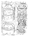
- Fig 2 is an enlarged partial perspective view of the filler neck closure assembly of Fig. 1 including an inhibitor housing coupled to a filler neck leading to the fuel tank and a nozzle inhibitor mounted for radially inward and outward floating movement in the inhibitor housing and showing that the inhibitor housing includes an interior block formed to include a funnel-shaped nozzle guide surface, an outer shell mounted on the interior block and formed to include a mouth opening into a nozzle-receiving passageway defined by the funnel-shaped nozzle guide surface, and a base coupled to the outer shell to define a flange-receiving space between the interior block and the base, and also showing that the nozzle inhibitor includes a nozzle conduit aligned with the nozzle-receiving passageway and configured to include an annular support flange arranged to extend into and float in radially inward and outward directions in the flange-receiving space, a closure including a spring-biased flapper door mounted for movement on the nozzle conduit between opened and closed positions, and a closure anchor coupled
- Fig. 3 is an exploded perspective assembly view of components included in the filler neck closure assembly shown in Fig. 2 showing that the inhibitor housing includes (in sequence from top to bottom on the left side of Fig. 3 ) an outer shell formed to include a nozzle-receiving mouth, an interior block arranged to extend upwardly into an interior region of the outer shell, and a base arranged to underlie the interior block and formed to include an interior region sized to house the nozzle inhibitor therein and showing that the nozzle inhibitor includes (in sequence from top to bottom on the right side of Fig.
- Fig. 3A is an enlarged perspective view of the hoop-shaped flapper door lock of Fig. 3 showing the variable-circumference band, a downwardly extending anti-rotation tab coupled to a middle portion of the variable-circumference band, a downwardly extending L-shaped first door-motion blocker coupled to a left-end portion of a curved strip defining the variable-circumference band, and a downwardly extending L-shaped second door-motion blocker coupled to a right-end portion of the curved strip that is arranged to lie in side-by-side sliding relation to the left-end portion of the curved strip;
- Fig. 3B is an inverted perspective view of a portion of the nozzle inhibitor of Figs. 2 and 3 showing that the flapper door is mounted to the guide housing for pivotable movement about a pivot axis and the flapper door return spring is coupled to a pivot rod included in the flapper door and arranged to engage the guide housing and a door plate included in the flapper door to yieldably urge the flapper door normally to its closed position and showing that the anti-rotation tab of the flapper door lock is arranged to extend into a channel formed at a 9 o'clock position in the guide housing and the first and second door-motion blockers are arranged to lie in a drawn-together formation to restrain a door tongue included in the flapper door to block pivotable movement of the flapper door about the pivot axis from the closed position toward an opened position;
- Fig. 3C is an enlarged perspective view of one of the arc-shaped band movers included in the multi-part lock opener shown in Figs. 2 and 3 and showing that each band mover includes an actuator including a curved push head and a radially inwardly extending push-head driver coupled to a concave surface on the push head, an upper guide post coupled to the top of the actuator, and a lower guide post coupled to the bottom of the actuator;
- each band mover includes an actuator including a curved push head and a radially inwardly extending push-head driver coupled to a concave surface on the push head, an upper guide post coupled to the top of the actuator, and a lower guide post coupled to the bottom of the actuator;
- Fig. 3D is a left-side elevation view of the arc-shaped band mover of Fig. 3C showing that the push-head driver includes a sloped ramp arranged to engage the tip of a downwardly moving large-diameter (diesel) fuel-dispensing nozzle during movement of such a nozzle through the filler neck closure assembly as suggested, for example, in Figs. 8, 10, and 12 ;
- the push-head driver includes a sloped ramp arranged to engage the tip of a downwardly moving large-diameter (diesel) fuel-dispensing nozzle during movement of such a nozzle through the filler neck closure assembly as suggested, for example, in Figs. 8, 10, and 12 ;
- Fig. 3E is a front elevation view of the arc-shaped band mover of Figs. 3C and 3D ;
- Fig. 4 is a perspective view of the nozzle inhibitor of Figs. 2 and 3 and a tip of a large-diameter (diesel) fuel-dispensing nozzle above the nozzle inhibitor, with a portion of the carrier shell included in the nozzle conduit removed to show a subassembly comprising the guide housing, closure anchor, and closure, and showing retention of the pivotable flapper door in the closed position by the drawn-together first and second door-motion blockers included in the flapper door lock of the nozzle inhibitor;
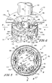
- Fig. 5 is a transverse sectional view of the nozzle inhibitor taken along line 5-5 of Fig. 4 showing the variable-circumference band of the flapper door lock in a normal narrow-diameter mode surrounding the six arc-shaped band movers and showing that the radially inwardly extending push-head driver included in each arc-shaped band mover is arranged normally to extend through a channel formed between two companion upstanding band-mover guards;
- Fig. 6 is a perspective view similar to Fig. 4 after movement of the tip of the large-diameter (diesel) fuel-dispensing nozzle into a central opening formed in the nozzle inhibitor to contact the sloped ramps on the six arc-shaped band movers and urge the push-head drivers of the band movers to slide in radially outward directions to assume retracted positions in channels formed in the guide housing of the nozzle inhibitor;
- Fig. 7 is a transverse sectional view of the nozzle inhibitor taken along line 7-7 of Fig. 6 showing expansion of the variable-circumference band of the flapper door lock in an expanded large-diameter mode in response to radially outward movement of each of the six arc-shaped band movers caused by axially inward movement of the tip of the large-diameter (diesel) fuel-dispensing nozzle to reach the pivotable flapper door included in the closure of the nozzle inhibitor;
- Figs. 8-13 comprise a series of sectional views that show how a large-diameter (diesel) fuel-dispensing nozzle expands the variable-circumference band of the flapper door lock to free the normally locked flapper door during insertion of the large-diameter (diesel) fuel-dispensing nozzle into the fuel tank filler neck during a tank refueling activity;
- Fig. 8 is an enlarged sectional view taken along line 8-8 of Fig. 5 ;
- Fig. 9 is an enlarged partial elevation view taken along line 9-9 of Fig. 5 showing the L-shaped first and second door-motion blockers of the flapper door lock in a drawn-together formation trapping a door tongue included in the flapper door therebetween to retain the flapper door affirmatively in the closed position;
- Fig. 10 is an enlarged sectional view taken along line 10-10 of Fig. 7 ;
- Fig. 11 is an enlarged partial elevation view taken along line 11-11 of Fig. 7 showing the L-shaped first and second door-motion blockers of the flapper door lock in a spread-apart formation to release a door tongue included in the flapper door to free the flapper door for pivotable movement about the axis of rotation toward an opened position as suggested in Figs. 12 and 13 ;
- Fig. 12 is a sectional view similar to Figs. 10 and 12 showing movement of the released flapper door relative to the inhibitor housing toward an opened position;
- Fig. 13 is a partial elevation view similar to Figs. 9 and 11 showing the flapper door in the partly opened position shown in Fig. 12 ;
- Fig. 14 is a partial perspective view similar to Fig. 2 of the filler neck closure assembly showing movement of an unauthorized small-diameter (unleaded) fuel-dispensing nozzle into the inhibitor housing and the nozzle inhibitor of Fig. 2 to reach and contact the flapper door while the flapper door is retained in the closed position by mating engagement of the door-motion blockers of the flapper door lock and the door tongue of the flapper door;
- Fig. 15 is a transverse sectional view taken along line 15-15 of Fig. 14 showing the variable-circumference band of the flapper door lock in the normal narrow-diameter mode surrounding the six arc-shaped band movers to cause the L-shaped first and second door-motion blockers to remain in the drawn-together formation shown, for example, in Fig. 9 so that the flapper door is retained in the closed position and suggesting that the six pairs of upstanding band-mover guards are arranged on the door plate to block movement of the small-diameter (unleaded) fuel-dispensing nozzle to cause all of the arc-shaped band movers to move in radially outward directions to expand the circumference of the variable-circumference band and thus unlock the flapper door lock;
- Fig. 16 is a view similar to Fig. 14 showing a first unsuccessful attempt to use an unauthorized small-diameter (unleaded) fuel-dispensing nozzle to actuate the lock opener to disable the flapper door lock in response to application of an operator-applied force to move the unauthorized small-diameter (unleaded) fuel-dispensing nozzle (to the right) relative to the nozzle inhibitor when the tip of that nozzle contacts an underlying door plate of the flapper door as a result of floating movement of the annular support flange of the nozzle conduit of the nozzle inhibitor in the space provided above the base and below the interior block caused by lateral movement of the unauthorized small-diameter (unleaded) fuel-dispensing nozzle relative to the nozzle inhibitor against some of the upstanding band-mover guards appended to a top surface of a door plate included in the flapper door;
- Fig. 17 is a view similar to Fig. 16 showing another unsuccessful attempt to use an unauthorized small-diameter (unleaded) fuel-dispensing nozzle to actuate the lock opener to disable the flapper door lock in response to application of an operator-applied force to move the unauthorized small-diameter (unleaded) fuel-dispensing nozzle laterally (to the right) relative to the nozzle inhibitor when the tip of that nozzle lies above the upstanding band-mover guards and in spaced-apart relation to the underlying door plate of the flapper door;
- Fig. 18 is a transverse sectional view taken along line 18-18 of Fig. 17 showing shifting of the nozzle inhibitor from a normal centered position shown, for example, in Fig. 15 to assume a three o'clock position in response to the operator-applied force on the unauthorized fuel-dispensing nozzle owing to the freedom of the annular support flange included in the carrier shell of the nozzle conduit to float in the space provided between the base and the interior block of the inhibitor housing;
- Fig. 19 is a perspective view (similar to Fig. 4 ) of a nozzle inhibitor including a flapper door lock modified as shown in Figs. 19A and 28 to provide means on the door-motion blockers for interlocking with the flapper door (modified as shown in Fig. 28 ) when an unauthorized force is applied to the arc-shaped band movers using a small-diameter fuel-dispensing nozzle as suggested in Figs. 28-32 affirmatively to retain the first and second door-motion blockers in a drawn-together formation so that the flapper door is retained in the closed position as suggested in Figs. 31 and 32 ;
- Fig. 20 is a transverse sectional view of the nozzle inhibitor taken along line 20-20 of Fig. 19 ;
- Figs. 21-26 comprise a series of sectional views that show how a large-diameter (diesel) fuel-dispensing nozzle expands the modified flapper door lock of Figs. 19 and 19A to free the normally locked flapper door during insertion of the large-diameter (diesel) fuel-dispensing nozzle into the fuel tank fill tube during a tank refueling activity;
- Fig. 21 is a sectional view taken along line 21-21 of Fig. 20 ;
- Fig. 22 is a sectional view taken along line 22-22 of Fig. 21 showing the L-shaped first and second door-motion blockers of the flapper door lock in a drawn-together formation trapping a door tongue included in the flapper door therebetween to retain the flapper door affirmatively in the closed position;
- Fig. 23 is a partial sectional view similar to Fig. 21 showing downward movement of the large-diameter (diesel) fuel-dispensing nozzle into the modified nozzle inhibitor of Fig. 19 ;
- Fig. 24 is a sectional view taken along line 24-24 of Fig. 23 showing the L-shaped first and second door-motion blockers of the flapper door lock in a spread-apart formation to release a door tongue included in the flapper door to free the flapper door for pivotable movement about an axis of rotation toward an opened position as suggested in Figs. 25 and 26 ;
- Fig. 25 is a partial sectional view similar to Figs. 21 and 23 showing movement of the released flapper door relative to the inhibitor housing toward an opened position;
- Fig. 26 is a sectional view taken along line 26-26 of Fig. 25 ;
- Figs. 27-32 comprise a series of sectional views (similar to Figs. 21-26 ) that show how the modified flapper door lock of Figs. 19 and 19A functions to interlock with the flapper door to retain the flapper door in a closed position when a small-diameter (unleaded) fuel-dispensing nozzle is used in an unauthorized manner in an attempt to unlock the flapper door lock by expanding the circumference (diameter) of a variable-circumference band included in the flapper door lock;
- Fig. 27 is a sectional view taken along line 27-27 of Fig. 20 except that the downwardly moving nozzle shown partially in section in Fig. 27 is a small-diameter (unleaded) fuel-dispensing nozzle that is not authorized to unlock the flapper door lock;
- Fig. 28 is a sectional view taken along line 28-28 of Fig. 27 showing that the underside of the door tongue included in the flapper door is formed to include a downwardly opening lug receiver channel and showing that a retainer lug is appended to the free end of each of the L-shaped first and second door-motion blockers of the modified flapper door lock and arranged to extend upwardly toward the overlying lug receiver channel;
- Fig. 29 is a partial sectional view similar to Fig. 27 showing movement of the small-diameter (unleaded) fuel-dispensing nozzle in the direction of the double arrow to engage and move at least one of arc-shaped band movers located on the right-hand side of the nozzle inhibitors in a radially outward direction (to the right) in an unauthorized effort to unlock the flapper door lock;
- Fig. 30 is a sectional view taken along line 30-30 of Fig. 29 ;
- Fig. 31 is a partial sectional view similar to Figs. 27 and 29 showing continued downward movement of the unauthorized small-diameter (unleaded) fuel-dispensing nozzle to engage the flapper door;
- Fig. 32 is a sectional view taken along line 32-32 of Fig. 31 showing that the retainer lug appended to the free end of the first (left side) door-motion blocker (of the modified flapper door lock of Figs. 19 and 19A ) extends upwardly into the downwardly opening lug receiver channel formed in the door tongue of the flapper door in response to slight downward pivoting movement of the flapper door (as shown in Fig. 31 ) to interlock the door tongue and the retainer lug so as to block expansion of the variable-circumference band, separation of the first and second door-motion blockers coupled to opposite ends of the variable-circumference band, and release of the flapper door.
- a nozzle inhibitor 10 is adapted to be mounted in a capless fill tube 100 as shown, for example, in Figs. 1-3 , 14, and 15 to block use of a small-diameter (unleaded) fuel-dispensing nozzle 20 to dispense non-diesel unleaded fuel into a fuel tank 14 of a diesel-engine vehicle 18.
- Nozzle inhibitor 10 is configured to allow a user to dispense diesel fuel into such a tank using a large-diameter (diesel) fuel-dispensing nozzle 22 as shown, for example, in Figs. 4-7 and 8-13 .
- Nozzle inhibitor 10 is also suitable for use in a traditional fill pipe closed by a fuel (gas) cap.
- Nozzle inhibitor 10 includes a flapper door lock 86 having a variable-circumference band 130 shown, in Figs. 2 and 3A and used normally to lock a flapper door 80 in a closed position in fuel tank fill tube 100 as suggested in Fig. 3B and Figs. 8 and 9 .
- a modified flapper door lock 286 is included in an alternative nozzle inhibitor 210 as suggested in Figs. 19-32 .
- a nozzle inhibitor 10 is associated with a capless fill tube 100 coupled to a vehicle fuel tank 14 as suggested in Fig. 1 to prevent a fuel-purchasing customer from using a fuel-dispensing pump nozzle to discharge unleaded fuel into a vehicle 18 having a diesel engine (not shown) requiring only diesel fuel.
- fill tube 100 includes a filler neck closure assembly 11 coupled to a filler neck 12 that is coupled to fuel tank 14.
- Nozzle inhibitor 10 is configured to block full insertion of a small-diameter unleaded fuel nozzle 20 into filler neck 12 as suggested in Figs. 4 and 5 .
- nozzle inhibitor 10 is configured to allow full insertion of a relatively large-diameter diesel fuel nozzle 22 into filler neck 12 as suggested in Figs. 9 and 10 .
- a filler neck closure assembly 11 containing nozzle inhibitor 10 is provided in a vehicle 18 normally to close a filler neck 12 extending from fuel tank 14 onboard vehicle 18.
- an outer filler neck access door 13 is moved relative to a vehicle body panel 15 to expose filler neck closure assembly 11 as shown, for example, in Fig. 1 .
- Filler neck closure assembly 11 is located in a chamber 17 formed in vehicle 18 so that filler neck closure assembly 11 is out of sight when access door 13 is closed.
- Small-diameter nozzle 20 is coupled to an unleaded fuel supply 19 by a hose 21.
- Large-diameter nozzle 22 is coupled to a diesel fuel supply 119 by another hose 21.
- both nozzles 20, 22 will be available at a filling station.
- Nozzle inhibitor 10 in filler neck closure assembly 11 in vehicle 18 functions to block a consumer from inadvertently using small-diameter nozzle 20 to discharge unleaded fuel into a fuel tank filler neck of a vehicle that uses only diesel fuel.
- filler neck closure assembly 11 includes a nozzle inhibitor 10 configured to include a minimal number of parts and an inhibitor housing 24 configured to support nozzle inhibitor 10 in communication with filler neck 12 as suggested in Figs. 2 and 14 .
- nozzle inhibitor 10 is mounted to float in radially outward and inward directions relative to inhibitor housing 24 as suggested in Figs. 16-18 to defeat attempts by an operator to insert a small-diameter (unleaded) fuel-dispensing nozzle 20 through filler neck closure assembly 11 and into filler neck 12 of diesel-engine vehicle 18.
- Nozzle inhibitor 10 is configured to provide means for blocking admission of small-diameter nozzle 20 into filler neck 12 (as suggested in Figs. 14 and 15 ) without blocking admission of large-diameter nozzle 22 into filler neck 12 (as suggested in Figs. 8-13 ).
- Inhibitor housing 24 includes an outer shell 26, an interior block 28, and a base 30 as suggested in Fig. 3 .
- Outer shell 26 cooperates with interior block 28 to form a crown 27 coupled to base 30 as suggested in Fig. 16 .
- Base 30 is configured to be coupled to an outer end of filler neck 12 as shown diagrammatically in Fig. 2 .
- nozzle inhibitor 10 is mounted in a stable position in an interior region 32 formed in base 30 so that nozzle inhibitor 10 is constrained to lie in a fixed axial position in inhibitor housing 24 yet is free to float laterally relative to base 30 in inhibitor housing 24 without falling through aperture 68 formed in base 30 if an operator attempts to push or otherwise move components included in nozzle inhibitor 10 relative to inhibitor housing 24 with the tip of an unauthorized small-diameter nozzle 20 in an unauthorized attempt to defeat security features of nozzle inhibitor 10.
- Outer shell 26 includes a top wall 34 and a cylinder-shaped side wall 36 depending from a round perimeter edge 37 of top wall 34 as shown in Fig. 3 .
- Top wall 34 includes an interior edge 38 defining a mouth 39 opening into an interior region 40 of outer shell 26 bounded by top wall 34 and side wall 36.
- a lower end 42 of side wall 36 is formed to include a radially outwardly opening channel 43 sized to receive a retainer band 44 or any suitable retainer therein as suggested diagrammatically in Fig. 2 .
- Interior block 28 is formed includes a cylindrical outer wall 46, an axially outer large-diameter opening 47, an axially inner relatively small-diameter opening 49, and a funnel-shaped nozzle guide surface 48 arranged to extend from large-diameter opening 47 to small-diameter opening 49 as shown best in Fig. 2 .
- Funnel-shaped nozzle guide surface 48 is configured to define an interior passageway 50 extending between openings 47 and 49.
- interior block 28 is configured to extend upwardly into interior region 40 through a bottom opening 45 formed in lower end 42 of side wall 36 to cause mouth 39 formed in top wall 34 of outer shell 26 to open into interior passageway 50 formed in interior block 28.
- annular channel 52 is formed in an upper portion of interior block 28 and arranged to surround large-diameter opening 47 and open upwardly toward the underside of top wall 34 of outer shell 26. Annular channel 52 is sized to house an O-ring seal (not shown) or other suitable seal means for establishing a sealed connection between interior block 28 and top wall 34.
- Base 30 includes a top wall 54 and a cylindrical side wall 56 depending from an outer perimeter portion of top wall 54 as shown in Figs. 2 and 3 . Walls 54 and 56 cooperate to form boundaries of interior region 32 as shown best in Fig. 2 .
- Top wall 54 is formed to include an interior edge 66 defining an aperture 68 opening into interior region 32 formed in base 30.
- An axially upwardly and radially outwardly opening annular channel 58 is formed on an exterior portion of base 30 at the intersection of top wall 54 and side wall 56 as suggested in Figs. 2 and 3 .
- a radially outwardly facing annular outer edge 60 of top wall 54 of base 30 mates with a cylindrical inner surface 41 of lower end 42 of outer shell 26 when outer shell 26 is mounted on base 30 as shown in Fig. 2 .
- An axially upwardly facing annular top edge 64 of side wall 56 of base 30 mates with a downwardly facing annular bottom edge 51 of lower end 42 of outer shell 26 when outer shell 26 is mounted on base 30 as shown in
- lower end 42 of outer shell 26 is inserted in annular channel 58 of base 30 after interior block 28 is lodged in interior region 40 formed in outer shell 26.
- Retainer band 44 or other suitable means is provided to fix outer shell 26 in a stationary position on base 30 while trapping interior block 28 therebetween so that a laterally extending flange-receiving space 70 is formed between a bottom surface of interior block 28 and a top surface of base 30.
- laterally extending flange-receiving flange 70 is formed between crown 27 and base 30 as suggested in Fig. 16 .
- Flange-receiving space 70 is sized to receive a portion (e.g., support flange 92) of nozzle inhibitor 10 to provide means for allowing floating movement of nozzle inhibitor 10 relative to interior block 28 and base 30 during unauthorized attempts to use a small-diameter (unleaded) fuel-dispensing nozzle 20 to unlock a normally locked flapper door 80 provided in nozzle inhibitor 10 to regulate admission of fuel-dispensing nozzles (e.g., nozzles 20 and 22) through filler neck closure assembly 11 into filler neck 12 as shown, for example, in Figs. 16-18 .
- fuel-dispensing nozzles e.g., nozzles 20 and 22
- nozzle inhibitor 10 includes a nozzle conduit 72 comprising a carrier shell 74 and a guide housing 76, a closure 78 comprising a flapper door 80 and a flapper door return spring 82, and a closure anchor 84 comprising a hoop-shaped flapper door lock 86 and a multi-part lock opener 88.
- Closure 78 is coupled to a bottom portion of guide housing 76 and is configured normally to close a nozzle-receiving passageway 90 formed in guide housing 76 as suggested in Fig. 2 .
- Closure anchor 84 is mounted on guide housing 76 as suggested in Figs.
- flapper door 80 in a closed position relative to guide housing 76 to block admission of small-diameter (unleaded) fuel-dispensing nozzle 20 through nozzle-receiving passageway 90 into filler neck 12 as suggested in Figs. 14 and 15 and for releasing flapper door 80 upon contact with a moving large-diameter (diesel) fuel-dispensing nozzle 22 so that flapper door 80 is moved by large-diameter nozzle 22 relative to guide housing 76 from the closed position to an opened position to allow passage of large-diameter nozzle 22 through nozzle-receiving passageway 90 into filler neck 12 as suggested in Figs. 6-7 and 8-13 .
- Carrier shell 74 includes a radially outwardly extending annular support flange 92 that is sized to fit into flange-receiving space 70 provided between interior block 28 and base 30 to support carrier shell 74, guide housing 76, closure 78, and closure anchor 84 in a selected axial position in interior region 32 of base 30 and to allow floating movement of nozzle inhibitor 10 in radially outward and inward directions relative to inhibitor housing 24 as suggested in Figs. 16-18 .
- Carrier shell 74 includes a floating annular support flange 92 and a housing mount 94 coupled to an interior edge 93 of annular support flange 92 as suggested in Figs. 2 and 3 .
- Annular support flange 92 also includes a round exterior edge 95.
- Housing mount 94 is formed to include a funnel-shaped nozzle guide wall 96, an annular top wall 97, and an annular side wall 98 formed to include a door notch 91 and a pair of circumferentially spaced-apart lug-receiving slots 99.
- An outer edge of annular top wall 97 is appended to a top edge of annular side wall 98.
- Funnel-shaped nozzle guide wall 96 is arranged to interconnect an interior edge 93 of annular support flange 92 and an inner edge of annular top wall 97 and to converge in a direction extending from annular support flange 92 to annular top wall 97 as suggested in Figs. 2 and 3 .
- An illustrative guide housing 76 is shown in Fig. 3 and includes an annular top wall 110, an outer rim 112, and an inner rim 114 arranged to interconnect outer rim 112 and annular top wall 110.
- Guide housing 76 also includes a pair of circumferentially spaced-apart curved lugs 116 arranged to extend in radially outward directions into lug-receiving slots 99 formed in annular side wall 98 of carrier shell 74 to fix guide housing 76 in a stationary mounted position in carrier shell 74 to establish a subassembly defining nozzle conduit 72.
- Guide housing 76 is configured to include guide means for supporting components included in lock opener 88 for movement relative to guide housing 76 to operate flapper door lock 86 and cause flapper door 80 to be released and thus free to be moved from a closed position to an opened position.
- inner rim 114 is formed to include six circumferentially spaced-apart head-receiving guide apertures 118 and has an internal diameter that is less than the internal diameter of outer rim 112.
- Outer rim 112 is formed to include five circumferentially spaced-apart lower guide slots 120 and each lower guide slot 120 is associated with only one of the head-receiving guide apertures 118 as suggested in Fig. 3 .
- outer rim 112 subtends an angle of about 270° and first and second ends 121, 122 of outer rim 112 are arranged to lie in spaced-apart relation to one another to define a finger-motion area 124 therebetween.
- Guide housing 76 also includes a cantilevered platform 126 coupled to inner rim 114 at one of the head-receiving guide apertures 118 and arranged to extend radially outwardly away from inner rim 114 midway between first and second ends 121, 122 of outer rim 112 as shown in Fig. 3 .
- Cantilevered platform 126 is formed to include a guide slot 120 associated with the head-receiving guide aperture 118 aligned with cantilevered platform 126.
- Annular top wall 110 is formed to include a downwardly opening upper guide slot 123 associated with each of the six head-receiving guide apertures 118 and arranged to lie in alignment with each of the six lower guide slots 120.
- Flapper door lock 86 is shown, for example, in Figs. 3 and 3A .
- Flapper door lock 86 includes a variable-circumference band 130, a downwardly extending first door-motion blocker 131 coupled to a first end portion 134 of band 130, and a downwardly extending second door-motion blocker 132 coupled to an opposite second end portion 136 of band 130.
- flapper door lock 86 is a monolithic element made of spring steel or other suitable elastic material and band 130 is defined by a curved strip having first and second end portions 134, 136. End portions 134, 136 are arranged to lie in side-by-side relation to one another as suggested in Figs.
- Each door-motion blocker 121, 122 is L-shaped and includes a downwardly extending blade 138 cantilevered to band 130 and an inwardly extending latch finger 139 coupled to a free end of a companion blade 138 as suggested in Fig. 3A .
- a downwardly extending anti-rotation tab 140 is coupled to a middle portion 135 of band 130 and arranged to extend into one of the lower guide slots 120 formed in guide housing 76 as suggested in Fig. 3B to limit rotation of band 130 about vertical axis 146 relative to guide housing 76 and to locate latch fingers 139 of first and second door-motion blockers 131, 132 in finger-motion area 124 formed in guide housing 76.
- the circumference (and diameter) of variable-circumference band 130 will vary (i.e., change) in response to movement of end portions 134, 136 relative to one another.
- variable-circumference band 130 to shift back and forth between a normal narrow-diameter mode (wherein band 130 has a small circumference) shown, for example, in Figs. 2 , 3 , 3A, 3B , 4, 5 , 8, 9 , and 14-18 and a radially outwardly expanded large-diameter mode (wherein band 130 has a relatively larger circumference) shown, for example, in Figs. 6, 7 , and 10-13 .
- Multi-part lock opener 88 is shown, for example, in Fig. 3 and, in an illustrative embodiment, comprises six separate arc-shaped band movers 142.
- Band movers 142 are arranged to lie in an interior region 144 formed inside variable-circumference band 130 as suggested in Figs. 3 , 5 , and 7 .
- Normally band 130 is coiled owing to elasticity of the spring material used to make band 130 to assume a narrow-diameter mode as shown in Fig. 5 to arrange band movers 142 in a packed relationship forming a circle and causing ends of adjacent band movers 142 to touch.
- the outer diameter of small-diameter (unleaded) fuel-dispensing nozzle 20 is not large enough to contact all the band movers 142 of multi-part lock opener 88 and move them in radially outer directions to expand the circumference (and diameter) of variable-circumference band 130 and cause band 130 to assume the large-diameter mode shown in Figs. 6 and 7 when small-diameter nozzle 20 is inserted into filler neck closure assembly 11.
- large-diameter (diesel) fuel-dispensing nozzle 22 has a relatively larger diameter and is able to spread arc-shaped band movers 142 away from a central axis 146 extending through flapper door lock 86 when large-diameter nozzle 22 is moved downwardly through nozzle-receiving passageway 90 formed in guide housing 76 toward flapper door 80 as suggested in Figs. 8, 10, and 12 .
- the spreading arc-shaped band movers 142 cooperate to expand the circumference (and diameter) of variable-circumference band 130 and move first and second door-motion blockers 131, 132 to assume a spread-apart formation releasing flapper door 80.
- Each band mover 142 includes an actuator 147, a lower guide post 148 coupled to the bottom of actuator 147, and an upper guide post 149 coupled to the top of actuator 147.
- Actuator 147 comprises a curved push head 150 and a radially inwardly extending push-head driver 152 coupled to a concave interior wall 154 of curved push head 150.
- a convex exterior wall 156 of curved push head 150 is formed to include three convex curved rails 161, 162, 163 sized and arranged to engage an interior surface of variable-circumference band 130.
- Push-head driver 152 includes a sloped ramp 158 shown in Figs.
- Lower guide post 148 is elongated and oblong and arranged to extend in a radial direction along a bottom portion of curved push head 150 and oblong push-head driver 152 and slide back and forth in a companion lower guide slot 120.
- Upper guide post 149 is cylindrical and sized to fit into and slide back and forth in a companion upper guide slot 123.
- Push-head driver 152 is sized to fit into and slide back and forth in a companion head-receiving guide aperture 118 formed in guide housing 76.
- Push-head driver 152 also includes a forward face 160 extending downwardly from sloped ramp 158 toward lower guide post 148.
- Flapper door 80 includes a pivot mount 170, a door tongue 172, and a door plate 174 arranged to interconnect pivot mount 170 and door tongue 172 as shown in Fig. 3 . Flapper door 80 also includes six pairs of upstanding band-mover guards 176 as shown in Fig. 3 . Each pair of band-mover guards 176 is formed to include a channel 178 therebetween arranged to receive a nose portion of push-head driver 152 as suggested in Figs. 2 , 4, and 5 when variable-circumference band 130 has assumed the narrow-diameter mode. Pivot mount 170 is coupled to guide housing 76 as suggested in Fig. 3B to establish a pivot axis 180.
- Door tongue 172 is arranged to extend through door notch 91 formed in carrier shell 74 to mate with first and second door-motion blockers 131, 132 normally to retain flapper door 80 in the closed position relative to guide housing 76 as shown, for example, in Figs. 2 , 4, and 5 .
- Flapper door return spring 82 includes a coiled portion 182 coupled to pivot mount 170 of flapper door 80, a first leg 184 arranged to engage guide housing 76, and a second leg 186 arranged to engage door plate 174 as suggested in Fig. 3B .
- Coiled portion 182 is arranged to interconnect first and second legs 184, 186.
- Return spring 82 is configured to provide means for yieldably moving flapper door 80 about pivot axis 180 normally to assume the closed position on guide housing 76 as shown, for example, in Figs. 2 and 3B .
- Flapper door 80 normally is held in its closed position by flapper door return spring 82.
- Anti-rotation tab 140 of hoop-shaped door lock 86 is arranged to extend into a channel 120 formed at a 9 o'clock position in guide housing 76 and first and second door-motion blockers 131, 132 are arranged to lie in a drawn-together formation as suggested in Figs. 4 and 9 to mate with and restrain a door tongue 172 included in the flapper door 80 while flapper door 80 is urged by return spring 82 to assume the closed position to block pivotable movement of the flapper door 80 about pivot axis 180 from the closed position toward an opened position.
- Anti-rotation tab 140 is coupled to guide housing 76 to block an operator from using an unauthorized nozzle to pull on one door-motion blocker 131, 132 more than the other door-motion blocker 131, 132 in an attempt to unlock flapper door lock 86.
- a tip of a large-diameter (diesel) fuel-dispensing nozzle 22 can be positioned above nozzle inhibitor 10 by a user.
- Pivotable flapper door 80 is retained in the closed position by the drawn-together first and second door-motion blockers 131, 132 included in flapper door lock 86 of nozzle inhibitor 10.
- Variable-circumference band 130 of flapper door lock 86 is shown in Fig. 5 in a normal narrow-diameter mode surrounding six arc-shaped band movers 142.
- Radially inwardly extending push-head driver 152 included in each arc-shaped band mover 130 is arranged normally to extend through a channel 178 formed between two companion upstanding band-mover guards 176.
- nozzle inhibitor 10 After movement of the tip of large-diameter (diesel) fuel-dispensing nozzle 22 into a central opening formed in nozzle inhibitor 10, the tip of nozzle 22 contacts sloped ramps 158 on the six arc-shaped band movers 142 and urges push-head drivers 152 of band movers 142 to slide in radially outward directions to assume retracted positions in channels (i.e., head-receiving guide apertures 118) formed in guide housing 76 of nozzle inhibitor 10 as suggested in Figs. 6 and 7 . Resulting expansion of variable-circumference band 130 of flapper door lock 86 to assume an expanded large-diameter mode is shown in Fig. 7 .
- Such expansion is effected in response to radially outward movement of each of the six arc-shaped band movers 142 caused by axially inward movement of the tip of the large-diameter (diesel) fuel-dispensing nozzle 22 to reach the pivotable flapper door 80 included in closure 84 of nozzle inhibitor 10.
- L-shaped first and second door-motion blockers of flapper door lock 86 are aligned normally as shown in Fig. 4 in a drawn-together formation trapping a door tongue 172 included in flapper door 80 therebetween to retain flapper door 80 affirmatively in the closed position.
- the L-shaped first and second door-motion blockers 131, 132 of flapper door lock 86 are shown in Fig. 11 after they have been moved to assume a spread-apart formation to release door tongue 172 included in flapper door 80 to free flapper door 80 for pivotable movement about pivot axis 180 toward an opened position as suggested in Figs. 12 and 13 . Movement of the released flapper door 80 relative to inhibitor housing 24 toward an opened position is shown in Fig. 12 .
- Fig. 14 Movement of an unauthorized small-diameter (unleaded) fuel-dispensing nozzle 20 into inhibitor housing 24 and nozzle inhibitor 10 to reach and contact flapper door 80 while flapper door 80 is retained in the closed position by mating engagement of door-motion blockers 131, 132 of flapper door lock 86 and door tongue 172 of flapper door 80 is shown in Fig. 14 .
- Variable-circumference band 130 of flapper door lock 86 is shown in Fig. 15 in the normal narrow-diameter mode surrounding six arc-shaped band movers 142 to cause the L-shaped first and second door-motion blockers 131, 132 to remain in the drawn-together formation shown, for example, in Fig. 9 so that flapper door 80 is retained in the closed position.
- the six pairs of upstanding band-mover guards 176 are arranged on door plate 174 to block movement of small-diameter (unleaded) fuel-dispensing nozzle 20 in the space formed in variable-circumference band 130 to cause all of arc-shaped band movers 142 to move in radially outward directions to expand the circumference of variable-circumference band 130 and thus unlock flapper door lock 86.
- a first unsuccessful attempt to use an unauthorized small-diameter (unleaded) fuel-dispensing nozzle 20 to actuate lock opener 88 to disable flapper door lock 86 is shown in Fig. 16 .
- An operator-applied force 101 is applied to move unauthorized small-diameter (unleaded) fuel-dispensing nozzle 20 (to the right) relative to nozzle inhibitor 10 when the tip of that nozzle 20 contacts an underlying door plate 174 of flapper door 80 and lies in a space surrounded by a ring of band-mover guards 176.
- Floating movement of annular support flange 92 of nozzle inhibitor 10 in the space 70 provided above base 30 and below interior block 28 is caused by lateral movement of the unauthorized small-diameter (unleaded) fuel-dispensing nozzle 176 relative to nozzle inhibitor 10 against some of the surrounding upstanding band-mover guards 176 appended to a top surface of a door plate 174 included in flapper door 80.
- Such lateral movement causes nozzle inhibitor 10 to move, for example, to an off-center position shown in Fig. 16 without causing any retracting motion of one of the arc-shaped band movers 142 into a companion guide aperture 118 formed in guide housing 76.
- FIG. 17 Another unsuccessful attempt to use an unauthorized small-diameter (unleaded) fuel-dispensing nozzle 20 to actuate lock opener 88 to disable flapper door lock 86 is shown in Fig. 17 in response to application of an operator-applied force 101 to move the unauthorized small-diameter (unleaded) fuel-dispensing nozzle 20 laterally (to the right) relative to nozzle inhibitor 10 when the tip of that nozzle 20 lies in a space above the ring of upstanding band-mover guards 176 and in spaced-apart relation to underlying door plate 174 of flapper door 80. Shifting of nozzle inhibitor 10 from a normal centered position shown, for example, in Fig. 15 to assume an off-center three o'clock position shown in Fig.
- a nozzle inhibitor 210 in accordance with another embodiment of the present disclosure is shown in Figs. 19-32 .
- Nozzle inhibitor 210 includes a modified flapper door lock 286 shown, for example, in Figs. 19, 19A, and 20 .
- nozzle inhibitor 210 is similar in construction to nozzle inhibitor 10.
- Flapper door lock 286 is shown in Figs. 19-32 . As suggested in Figs. 19, 19A, and 20 , flapper door lock 286 includes variable-circumference band 130, downwardly extending first door-motion blocker 131, downwardly extending second door-motion blocker 132, a first retainer lug 231 coupled to first door-motion blocker 131, and a second retainer lug 232 coupled to second door-motion blocker 132.
- first retainer lug 231 is appended to a free end of inwardly extending latch finger 139 of first door-motion blocker 131.
- First retainer lug 231 is arranged to extend upwardly therefrom to lie in spaced-apart relation to downwardly extending blade 138 of first door-motion blocker 131 to define a first rail-receiving channel 331 therebetween.
- second retainer lug 232 is appended to a free end of inwardly extending latch finger 139 of second door-motion blocker 132.
- Second retainer lug 232 is arranged to extend upwardly therefrom to lie in spaced-apart relation to downwardly extending blade 138 of second door-motion blocker 132 to define a second rail-receiving channel 332 therebetween.
- Nozzle inhibitor 210 includes a flapper door 280 that is similar to flapper door 80 except that it is formed to include a downwardly opening lug receiver channel 283 as shown, for example, in Figs. 22, 24 , 28, and 30 .
- Each of retainer lugs 231, 232 is arranged to lie under and extend upwardly toward downwardly opening lug receiver channel 283 when flapper door 280 lies in a normally closed position in fill tube 100 as suggested in Figs. 22, 24, 26 , and 28 .
- Flapper door 280 includes first and second rails 281, 282 a suggested in Fig. 28 . Rails 281, 282 are arranged to lie in spaced-apart relation to one another to locate the downwardly opening lug receiver channel 283 therebetween.
- flapper door lock 286 and flapper door 280 The interlocking connection between flapper door lock 286 and flapper door 280 is established when flapper door 280 moves relative to flapper door lock 286 to cause (1) first and second retainer lugs 281, 282 in flapper door lock 286 to extend upwardly into downwardly opening lug receiver channel 283 formed in flapper door 280 and/or (2) one of the first and second rails 281, 282 in flapper door 280 extends downwardly into a companion one of the rail-receiving channels 331, 332 formed in flapper door lock 286.
Landscapes
- Engineering & Computer Science (AREA)
- Life Sciences & Earth Sciences (AREA)
- Sustainable Development (AREA)
- Sustainable Energy (AREA)
- Chemical & Material Sciences (AREA)
- Combustion & Propulsion (AREA)
- Transportation (AREA)
- Mechanical Engineering (AREA)
- Cooling, Air Intake And Gas Exhaust, And Fuel Tank Arrangements In Propulsion Units (AREA)
Abstract
Claims (20)
- Ensemble de bouchon de goulot de remplissage associé à un goulot de remplissage de réservoir de carburant de véhicule, l'ensemble (11) comprenant :des moyens inhibiteurs (10, 210) pour empêcher l'insertion d'un pistolet de pompe de distribution de carburant sans plomb de petit diamètre (20) dans une voie de passage de conduction de carburant formée dans un goulot de remplissage (12) couplé à un réservoir de carburant (14) de véhicule tout en permettant l'insertion d'un pistolet de pompe de distribution de carburant diesel de grand diamètre (22) dans la voie de passage de conduction de carburant formée dans le goulot de remplissage (12), les moyens inhibiteurs (10, 210) comprenant un conduit de pistolet (72) formé dans le tube de remplissage (100) et formé pour comprendre une voie de passage de réception de pistolet (90), une porte à clapet (80, 280) montée pour le mouvement par rapport au conduit de pistolet (72) pour ouvrir et fermer la voie de passage de réception de pistolet (90), et un ancrage de porte à clapet (84) couplé au conduit de pistolet (72) et associé avec la porte à clapet (80, 280), etdans lequel l'ancrage de porte à clapet (84) comprend un verrouillage de porte à clapet de forme circulaire (86, 286) et un dispositif d'ouverture de verrouillage (88) couplé au conduit de pistolet (72) et au verrouillage de porte à clapet de forme circulaire (86, 286) ;caractérisé en ce que :le verrouillage de porte à clapet de forme circulaire (86, 286) comprend une bande à circonférence variable (130) qui est expansible pour passer d'un mode de diamètre étroit normal caractérisé par un premier diamètre et une première circonférence à un mode de grand diamètre caractérisé par un deuxième diamètre et une deuxième circonférence relativement plus grands, un bloqueur de mouvement de porte (131) couplé à une première partie d'extrémité (134) de la bande à circonférence variable (130), et un deuxième bloqueur de mouvement de porte (132) couplé à une deuxième partie d'extrémité (136) de la bande à circonférence variable (130) et agencé normalement pour coopérer avec le premier bloqueur de mouvement de porte (131) pour adopter une formation contractée pour piéger la porte à clapet (80, 280) entre eux, lorsque la bande à circonférence variable (130) adopte le mode de diamètre étroit afin de retenir la porte à clapet (80, 280) dans une position fermée, fermant l'ouverture de réception de pistolet,et en ce que le dispositif d'ouverture de verrouillage (88) est un dispositif d'ouverture de verrouillage à plusieurs parties qui comprend plusieurs dispositifs de déplacement de bande (142) positionnés dans une région intérieure (144) formée dans la bande à circonférence variable (130) et agencés pour être le long d'une surface intérieure de la bande à circonférence variable en relation espacée les uns des autres, etdans lequel les dispositifs de mouvement de bande (142) coopèrent pour se déplacer par rapport à la bande à circonférence variable (130) et les uns par rapport aux autres afin d'expanser le diamètre et la circonférence de la bande à circonférence variable afin d'adopter le mode de grand diamètre et déplacer les premier et deuxième bloqueurs de mouvement de porte (131, 132) à distance l'un de l'autre pour adopter une formation déployée dégageant la porte à clapet (80, 280) afin de libérer la porte à clapet en réponse au mouvement du pistolet de distribution de carburant de grand diamètre (22) à travers la voie de passage de réception de pistolet (90) formée dans le circuit de pistolet (72) afin de mettre en prise les dispositifs de mouvement de bande (142) et déplacer les dispositifs de mouvement de bande dans des directions radialement vers l'extérieur afin d'expanser la bande à circonférence variable (130).
- Ensemble selon la revendication 1, dans lequel la bande à circonférence variable est enroulée normalement pour prendre le mode de diamètre étroit en raison de l'élasticité du matériau de ressort formé pour fabriquer la bande à circonférence variable, la bande à circonférence variable dans le mode de diamètre étroit est agencée pour pousser les dispositifs de mouvement de bande (142) afin de se déplacer dans les directions radialement vers l'intérieur vers un axe central passant par un espace délimité par la bande à circonférence variable, chaque dispositif de mouvement de bande est agencé dans l'espace pour entrer en contact avec un pistolet de distribution de carburant de grand diamètre (22) se déplaçant à travers l'espace, et pour se déplacer radialement vers l'extérieur à distance de l'axe central pour expanser la bande à circonférence variable afin d'amener la bande à circonférence variable à passer du mode de diamètre étroit pour adopter le mode de grand diamètre, et les dispositifs de mouvement de bande sont agencés selon un modèle déployé pour amener au moins certains des dispositifs de mouvement de bande à éviter le contact avec un pistolet de distribution de carburant de petit diamètre (20) passant par l'espace afin d'empêcher l'expansion de la bande à circonférence variable pour amener la bande à circonférence variable à rester dans le mode de diamètre étroit en réponse au mouvement du pistolet de distribution de carburant de petit diamètre le long de l'axe central et à travers l'espace.
- Ensemble selon la revendication 2, dans lequel chaque dispositif de mouvement de bande (142) est en forme d'arc et la bande à circonférence variable (130) est agencée pour appliquer une force dirigée radialement vers l'intérieur sur chaque dispositif de mouvement de bande normalement pour agencer les dispositifs de mouvement de bande en relation conditionnée formant un cercle et amenant les extrémités des dispositifs de mouvement de bande adjacents à entrer en contact lorsque la bande à circonférence variable adopte le mode de diamètre étroit.
- Ensemble selon la revendication 3, dans lequel chaque dispositif de déplacement de bande (142) comprend un actionneur (147) et un guide (148, 149) couplé à l'actionneur et agencé pour s'étendre dans et se déplacer d'avant en arrière dans une fente (120, 123) formée dans le conduit de pistolet (72) pendant le mouvement de l'actionneur par rapport au conduit de pistolet en réponse à une force appliquée à l'actionneur par un pistolet de distribution de carburant de grand diamètre (22) se déplaçant le long de l'axe central et dans l'espace.
- Ensemble selon la revendication 4, dans lequel le guide comprend un montant de guidage inférieur (148) couplé à un fond de l'actionneur (147) et agencé pour s'étendre dans une première direction à distance de l'actionneur dans une première fente auxiliaire (120) formée dans le conduit de pistolet et un montant de guidage supérieur (149) couplé à une partie supérieure de l'actionneur (147) et agencé pour s'étendre dans une deuxième direction opposée à distance de l'actionneur dans une deuxième fente auxiliaire (123) formée dans le conduit de pistolet.
- Ensemble selon la revendication 4, dans lequel l'actionneur comprend un dispositif d'entraînement de tête de poussée (152) formé pour comprendre une rampe inclinée (158) agencée pour fournir des moyens pour mettre en prise une pointe d'un pistolet de distribution de carburant de grand diamètre mobile (22) se déplaçant vers le bas le long de l'axe central à travers l'espace, le dispositif d'entraînement de tête de poussée (152) est agencé pour se déplacer radialement vers l'extérieur à distance de l'axe central en réponse à l'application d'une force externe sur la rampe inclinée par la buse de distribution de carburant de grand diamètre mobile, l'actionneur (147) comprend en outre une tête de poussée (150) comprenant une paroi externe (156) agencée pour faire face à la surface intérieure de la bande à circonférence variable (130) et une paroi intérieure agencée pour être orientée vers l'axe central, et le dispositif d'entraînement de tête de poussée (152) est couplé à la paroi intérieure de la tête de poussée (150) pour pousser la tête de poussée afin de s'éloigner de l'axe central pour appliquer une force d'expansion sur la bande à circonférence variable de surface intérieure pour expanser la bande à circonférence variable afin d'adopter le mode de grand diamètre en réponse au mouvement radialement vers l'extérieur du dispositif d'entraînement de tête de poussée.
- Ensemble selon la revendication 1, dans lequel la porte à clapet (80) comprend un dispositif de montage de pivot (170), une languette de porte (172) et une plaque de porte (174) agencée pour interconnecter le dispositif de montage de pivot et la languette de porte, le dispositif de montage de pivot est couplé au conduit de pistolet (72) pour supporter la porte à clapet pour le mouvement pivotant autour d'un axe de pivot entre les positions ouverte et fermée, et les premier et deuxième bloqueurs de mouvement de porte (131, 132) coopèrent dans la formation contractée pour se coupler avec et retenir la languette de porte (172) lorsque la porte à clapet est dans la position fermée pour empêcher le mouvement pivotant de la porte à clapet de la position fermée vers une position ouverte.
- Ensemble selon la revendication 7, dans lequel la bande à circonférence variable (130) est réalisée avec un matériau élastique configuré pour établir normalement la bande à circonférence variable en mode de diamètre étroit, comprend une bande incurvée ayant les première et deuxième parties d'extrémité (134, 136), et les première et deuxième parties d'extrémité sont agencées pour se trouver en relation côte à côte entre elles afin de se déplacer l'une par rapport à l'autre en relation de coulissement pendant le passage de la bande à circonférence variable du mode de diamètre étroit au mode de grand diamètre.
- Ensemble selon la revendication 8, dans lequel chacun des premier et deuxième bloqueurs de mouvement de porte (131, 132) est en forme de L et comprend une lame s'étendant vers le bas (138) en porte-à-faux par rapport à la bande à circonférence variable (130) et un doigt de verrouillage (139) s'étendant vers l'intérieur couplé à une extrémité libre d'une lame auxiliaire (138) s'étendant vers le bas, le doigt de verrouillage (139) s'étendant vers l'intérieur du premier bloqueur de mouvement de porte (131) s'étend dans la première direction, et le doigt de verrouillage (139) s'étendant vers l'intérieur du deuxième bloqueur de mouvement de porte (132) s'étend dans une deuxième direction opposée vers le doigt de verrouillage s'étendant vers l'intérieur du premier bloqueur de mouvement de porte.
- Ensemble selon la revendication 9, dans lequel la porte à clapet (280) est formée pour comprendre un canal de réception de patte d'ouverture descendante (283) et le verrouillage de porte à clapet de forme circulaire (286) comprend en outre une première patte de retenue (231) couplée au premier bloqueur de mouvement de porte (131) et agencée pour s'étendre vers le haut vers le canal de réception de patte d'ouverture descendante (283).
- Ensemble selon la revendication 9, dans lequel la languette de porte (172) s'étend dans un espace bordé en partie par les première et deuxième parties d'extrémité (134, 136) de la bande à circonférence variable (130), des parties espacées des lames s'étendant vers le bas des premier et deuxième bloqueurs de mouvement de porte et les parties bout à bout des premier et deuxième bloqueurs de mouvement de porte.
- Ensemble selon la revendication 8, dans lequel le verrouillage de porte à clapet de forme circulaire (86) comprend en outre une languette anti-rotation (140) couplée à la bande incurvée de la bande à circonférence variable et agencée pour s'étendre dans un canal formé dans le conduit de pistolet (72) pour fournir des moyens pour empêcher un opérateur d'utiliser un pistolet de distribution de carburant non autorisé pour tirer sur l'un parmi les premier et deuxième bloqueurs de mouvement de porte (131, 132) plus que l'autre parmi les premier et deuxième bloqueurs de mouvement de porte dans une tentative de débloquer le verrouillage de porte à clapet de forme circulaire (86) en séparant les premier et deuxième bloqueurs de mouvement de porte de la languette de porte (172) de la porte à clapet (80).
- Ensemble selon la revendication 7, dans lequel la porte à clapet (80) comprend en outre une paire de protections de dispositif de déplacement de bande droites (176) couplées à la plaque de porte (174) et agencées pour s'étendre vers le haut vers un pistolet de distribution de carburant se déplaçant à travers la voie de passage de réception de pistolet (90) vers la plaque de porte et la paire de protections de dispositif de déplacement de bande droites (176) est formée pour comprendre un canal (178) entre elles afin de recevoir une partie de nez de l'un des dispositifs d'entraînement de tête de poussée (152) lorsque la bande à circonférence variable (130) a adopté le mode de diamètre étroit.
- Ensemble selon la revendication 13, dans lequel la porte à clapet (80) comprend plusieurs paires de protections de dispositif de déplacement de bande droites (176) couplées à la plaque de porte (174) et agencées pour s'étendre vers le haut vers un pistolet de distribution de carburant passant par la voie de passage de réception de pistolet (90) vers la plaque de porte et les paires de protections de dispositif de mouvement de bande droite (176) coopèrent pour définir des moyens pour empêcher le mouvement d'un pistolet de distribution de carburant de petit diamètre (20) dans l'espace formé dans la bande à circonférence variable (130) pour amener la totalité des dispositifs de mouvement de bande (142) à se déplacer dans les directions radialement externes afin d'expanser la circonférence de la bande à circonférence variable et débloquer ainsi le verrouillage de porte à clapet de forme circulaire (86) en séparant les premier et deuxième bloqueurs de mouvement de porte (131, 132) de la languette de porte (172) de la porte à clapet (80).
- Ensemble selon la revendication 1, comprenant en outre un boîtier inhibiteur (24) adapté pour être couplé à une extrémité externe du goulot de remplissage (12) et formé pour comprendre des moyens formant flotteur pour supporter le conduit de pistolet (72) pour le mouvement flottant latéral dans une région intérieure du tube de remplissage (100) par rapport au tube de remplissage pour empêcher les tentatives non autorisées par un opérateur d'utiliser un pistolet de distribution de carburant de petit diamètre afin de débloquer une porte à clapet normalement verrouillée pour réguler l'admission des pistolets de distribution de carburant à travers le tube de remplissage et l'ouverture de réception de pistolet formée dans la paroi du tube de remplissage.
- Ensemble selon la revendication 15, dans lequel le conduit de pistolet (72) comprend un rebord de support (92), le boîtier inhibiteur (24) est formé pour comprendre une région intérieure (32) et un espace de réception de rebord (70) s'ouvrant dans la région intérieure du boîtier inhibiteur et définissant les moyens formant flotteur, et les rebords de support (92) s'étendent dans l'espace de réception de rebord (70) pour permettre le mouvement flottant latéral du conduit de pistolet (72) dans la région intérieure (32) du boîtier inhibiteur (24) pendant les tentatives non autorisées d'utiliser un pistolet de distribution de carburant de petit diamètre pour débloquer la porte à clapet (80) normalement bloquée.
- Ensemble selon la revendication 16, dans lequel le boîtier inhibiteur (24) comprend une base (30) adaptée pour être couplée à une extrémité externe d'un goulot de remplissage (12) et formée pour comprendre la région intérieure (32) du boîtier inhibiteur et une couronne (27) couplée à une partie externe de la base (30) afin de former l'espace de réception de rebord (70) entre eux.
- Ensemble selon la revendication 17, dans lequel la couronne (27) comprend un bloc intérieur (28) positionné en relation espacée par rapport à la base (30) afin de définir l'espace de réception de rebord (70) entre eux, et une coque externe (26) agencée pour entourer et se coupler avec le bloc intérieur (28) et couplée à la base (30) pour retenir le bloc intérieur (28) dans une position fixe par rapport à la base (30).
- Ensemble selon la revendication 16, dans lequel le conduit de pistolet (72) comprend en outre une coque de support (74) et un boîtier de guidage (76) couplé à la coque de support pour se déplacer avec cette dernière dans la région intérieure (32) du boîtier inhibiteur (24), la porte à clapet (80) est couplée au boîtier de guidage (76), et la coque de support (74) est formée pour comprendre le rebord de support (92).
- Ensemble selon la revendication 19, dans lequel la coque de support (74) comprend un dispositif de montage de boîtier (94) couplé au rebord de support (92) et au boîtier de guidage (76).
Applications Claiming Priority (2)
| Application Number | Priority Date | Filing Date | Title |
|---|---|---|---|
| US95076407P | 2007-07-19 | 2007-07-19 | |
| PCT/US2008/069926 WO2009012197A2 (fr) | 2007-07-19 | 2008-07-14 | Mecanisme de blocage de pistolet de distribution de carburant |
Publications (3)
| Publication Number | Publication Date |
|---|---|
| EP2181009A2 EP2181009A2 (fr) | 2010-05-05 |
| EP2181009A4 EP2181009A4 (fr) | 2010-07-28 |
| EP2181009B1 true EP2181009B1 (fr) | 2012-06-27 |
Family
ID=40260325
Family Applications (1)
| Application Number | Title | Priority Date | Filing Date |
|---|---|---|---|
| EP08781771A Active EP2181009B1 (fr) | 2007-07-19 | 2008-07-14 | Mecanisme de blocage de pistolet de distribution de carburant |
Country Status (3)
| Country | Link |
|---|---|
| US (2) | US7967041B2 (fr) |
| EP (1) | EP2181009B1 (fr) |
| WO (1) | WO2009012197A2 (fr) |
Cited By (1)
| Publication number | Priority date | Publication date | Assignee | Title |
|---|---|---|---|---|
| US10000117B2 (en) | 2012-02-17 | 2018-06-19 | Stant Usa Corp. | Filler neck closure assembly |
Families Citing this family (31)
| Publication number | Priority date | Publication date | Assignee | Title |
|---|---|---|---|---|
| JP2008254816A (ja) * | 2007-03-31 | 2008-10-23 | G Cartier Technologies | 容器に流体を供給する際のエラーを回避する装置 |
| CA2654820C (fr) | 2008-02-21 | 2012-09-11 | Stant Manufacturing Inc. | Dispositif bloquant l'insertion d'une buse de distribution de carburant |
| DE112009001823T5 (de) * | 2008-08-20 | 2011-06-01 | Illinois Tool Works Inc., Glenview | Fehlbetankungssperre |
| US8763656B2 (en) * | 2008-08-25 | 2014-07-01 | Nifco Inc. | Device for preventing fueling error |
| US20100218849A1 (en) * | 2009-02-27 | 2010-09-02 | Toyoda Gosei Co., Ltd. | Fuel tank opening-closing device |
| JP5596712B2 (ja) * | 2009-03-12 | 2014-09-24 | イリノイ トゥール ワークス インコーポレイティド | 給油ミス防止装置 |
| WO2011062193A1 (fr) * | 2009-11-18 | 2011-05-26 | 株式会社ニフコ | Dispositif pour éviter les erreurs de choix de carburant |
| US8539993B2 (en) * | 2010-03-31 | 2013-09-24 | Toyoda Gosei Co., Ltd. | Fuel tank opening and closing device |
| US8430140B2 (en) * | 2010-05-05 | 2013-04-30 | Ford Flobal Technologies, LLC | Capless fuel-filling closure assembly |
| US8308014B2 (en) * | 2010-10-05 | 2012-11-13 | Chun-Li Chen | Fuel cap of internal combustion device |
| FR2975048B1 (fr) * | 2011-05-12 | 2013-06-28 | Itw De France | Tete pour tubulure de remplissage en carburant d'un reservoir de vehicule |
| JP5370420B2 (ja) * | 2011-06-10 | 2013-12-18 | トヨタ自動車株式会社 | 燃料タンクの給油部構造 |
| DE102011117459A1 (de) * | 2011-06-29 | 2013-01-03 | Volkswagen Aktiengesellschaft | Einfüllstutzen für einen Kraftstoffbehälter |
| DE102011120787A1 (de) * | 2011-06-29 | 2013-01-03 | Volkswagen Aktiengesellschaft | Fehlbetankungsschutzvorrichtung für einen Einfüllstutzen eines Kraftstoffbehälters |
| JP5715550B2 (ja) * | 2011-11-24 | 2015-05-07 | 京セラ株式会社 | 電子機器の蓋ロック機構 |
| DE112013001045T5 (de) * | 2012-02-20 | 2014-12-04 | Honda Motor Co., Ltd. | Struktur für einen Einfüllabschnitt von einem Kraftstoffeinfüllrohr |
| GB2499677A (en) * | 2012-02-27 | 2013-08-28 | Timothy Charles Harker | Preventing incorrect fuelling of a vehicle |
| EP2636555B1 (fr) * | 2012-03-08 | 2014-04-30 | Magna Steyr Fuel Systems GmbH | Tubulures de remplissage pour un réservoir de carburant diesel doté d'un dispositif de verrouillage |
| JP5907028B2 (ja) * | 2012-09-28 | 2016-04-20 | 豊田合成株式会社 | 燃料タンクの開閉装置 |
| US9415679B2 (en) | 2013-03-22 | 2016-08-16 | Stant Usa Corp. | Fuel-dispensing nozzle inhibitor |
| KR101417637B1 (ko) * | 2013-05-08 | 2014-07-08 | 현대자동차주식회사 | 혼유 방지 필러넥 장치 |
| US9701194B2 (en) | 2013-05-10 | 2017-07-11 | Stant Usa Corp. | Fuel-dispensing nozzle inhibitor |
| KR101481272B1 (ko) * | 2013-05-28 | 2015-01-09 | 현대자동차주식회사 | 혼유 방지 필러넥 장치 |
| KR101500136B1 (ko) * | 2013-09-06 | 2015-03-06 | 현대자동차주식회사 | 차량의 오주유 방지장치 |
| JP6231843B2 (ja) * | 2013-10-11 | 2017-11-15 | 株式会社アステア | 誤給油防止装置 |
| KR101481343B1 (ko) * | 2013-12-10 | 2015-01-09 | 현대자동차주식회사 | 차량의 혼유 방지 시스템 |
| KR101510051B1 (ko) * | 2014-04-16 | 2015-04-07 | 현대자동차주식회사 | 차량의 혼유 방지 시스템 |
| US10081241B2 (en) * | 2015-12-10 | 2018-09-25 | Curtis Alan Roys | Diesel fuel guard |
| JP6520778B2 (ja) * | 2016-03-17 | 2019-05-29 | 豊田合成株式会社 | 給油口の閉止装置 |
| JP6693019B2 (ja) * | 2016-10-14 | 2020-05-13 | 豊田合成株式会社 | 給油装置 |
| FR3067987B1 (fr) * | 2017-06-26 | 2019-08-09 | Microtechnic | Dispositif de detrompage pour conduit de remplissage en carburant d’un reservoir de vehicule et vehicule comprenant ce dispositif |
Family Cites Families (42)
| Publication number | Priority date | Publication date | Assignee | Title |
|---|---|---|---|---|
| US3730216A (en) * | 1972-04-06 | 1973-05-01 | Ford Motor Co | Fuel tank insert for admitting preselected pump nozzles |
| US4034784A (en) * | 1974-08-14 | 1977-07-12 | General Motors Corporation | Filler neck to inhibit use of leaded fuel |
| US4248279A (en) * | 1979-05-03 | 1981-02-03 | Chrysler Corporation | Tamper resistant fuel filler restrictor assembly |
| US4687034A (en) * | 1986-05-28 | 1987-08-18 | Shell Oil Company | Controlled release insert for a diesel fuel supply nozzle and method of adding a petroleum substrate over said insert |
| GB2230765B (en) | 1989-04-15 | 1992-12-02 | Ford Motor Co | Fuel tank filler pipe insert |
| DE4039269C1 (en) | 1990-12-08 | 1992-02-06 | Mercedes-Benz Aktiengesellschaft, 7000 Stuttgart, De | Self-closing fuel tank seal for filling tube - has lock automatically securing closure cap on filling aperture sealing seat |
| US5212864A (en) * | 1991-09-04 | 1993-05-25 | Arvin Industries, Inc. | Nozzle restrictor assembly and method of installing same |
| US5271438A (en) | 1992-06-22 | 1993-12-21 | Stant Manufacturing Inc. | Capless vehicle refueling system with moving fill passageway |
| US5322100A (en) * | 1993-01-27 | 1994-06-21 | Borg-Warner Automotive, Inc. | Fuel filler module |
| US5439129A (en) * | 1994-07-06 | 1995-08-08 | Borg-Warner Automotive, Inc. | Fuel tank filler pipe arrangement |
| FR2741014B1 (fr) | 1995-11-15 | 1998-01-09 | Peugeot | Dispositif detrompeur pour le conduit de remplissage en carburant d'un vehicule automobile |
| US5738359A (en) * | 1996-02-23 | 1998-04-14 | Npc Acquisition Corp. | Expandable band and locking mechanism for installing a flexible sealing element |
| FR2761934B1 (fr) | 1997-04-14 | 1999-05-14 | Journee Paul Sa | Dispositif de remplissage d'un reservoir de carburant pour un vehicule automobile comportant une tete de remplissage a armature de renfort |
| FR2762807B1 (fr) | 1997-04-30 | 1999-06-25 | Coutier Moulage Gen Ind | Embout de fermeture pour tubulure de remplissage d'un reservoir de carburant d'un vehicule automobile |
| US6152455A (en) * | 1998-07-09 | 2000-11-28 | Npc, Inc. | Expandable band and locking mechanism |
| WO2000020292A1 (fr) * | 1998-10-06 | 2000-04-13 | Stant Manufacturing Inc. | Couvercle de goulot de remplissage a limitation de torsion et a couplage rapide |
| DE10037824B4 (de) * | 2000-08-03 | 2009-06-10 | Daimler Ag | Vorrichtung zum Verhindern des Einführens einer Zapfpistole |
| US6302169B1 (en) * | 2000-09-13 | 2001-10-16 | Peter C. Pulos | Diesel fuel nozzle restrictor |
| GB2375530A (en) * | 2001-05-16 | 2002-11-20 | Anthony Keith Webb | Fuel filling system |
| DE10126207A1 (de) | 2001-05-30 | 2003-01-16 | Bayerische Motoren Werke Ag | Kraftfahrzeug-Kraftstofftank mit einem Einfüllstutzen zur Aufnahme einer Zapfpistole für Dieselkraftstoff |
| DE10139665A1 (de) | 2001-08-11 | 2003-02-20 | Bayerische Motoren Werke Ag | Kraftfahrzeug-Kraftstofftank mit einem Einfüllstutzen zur Aufnahme einer Zapfpistole für Dieselkraftstoff |
| US6539990B1 (en) * | 2001-11-20 | 2003-04-01 | Illinois Tool Works Inc. | Capless refueling assembly |
| DE10157090C1 (de) | 2001-11-21 | 2003-04-24 | Arno Goettsche | Anordnung zum Verhindern des Betankens eines Dieselfahrzeuges mit bleifreiem Benzin |
| DE50112972D1 (de) | 2001-12-14 | 2007-10-18 | Ford Global Tech Llc | Vorrichtung zur Betankung von Dieselfahrzeugen |
| US6722407B2 (en) * | 2002-08-07 | 2004-04-20 | Daimlerchrysler Corporation | Capless fuel refilling system |
| US6923226B2 (en) * | 2003-07-01 | 2005-08-02 | Patrick Wesley Bartlett | Device for preventing entry of an unleaded gas fill nozzle in a diesel fuel filler neck |
| US6923224B1 (en) * | 2004-01-15 | 2005-08-02 | Stant Manufacturing Inc. | Closure and vent system for capless filler neck |
| DE102004002994B3 (de) | 2004-01-19 | 2005-09-22 | Itw Automotive Products Gmbh & Co. Kg | Einfüllstutzen für das Einfüllen von Kraftstoff in einen Fahrzeugtank |
| US7077178B2 (en) * | 2004-08-11 | 2006-07-18 | Stant Manufacturing Inc. | Fuel-dispensing nozzle inhibitor |
| US7182111B2 (en) * | 2004-08-11 | 2007-02-27 | Stant Manufacturing Inc. | Fuel-dispensing nozzle inhibitor |
| US7302977B2 (en) * | 2004-09-30 | 2007-12-04 | Stant Manufacturing Inc. | Fuel-dispensing nozzle inhibitor |
| US6968874B1 (en) * | 2004-10-07 | 2005-11-29 | Martinrea Industries, Inc. | Capless automotive fueling system |
| US7665493B2 (en) * | 2005-02-10 | 2010-02-23 | Stant Manufacturing Inc. | Fuel-dispensing nozzle inhibitor |
| US7293586B2 (en) * | 2005-06-22 | 2007-11-13 | Stant Manufacturing Inc. | Fuel-dispensing nozzle inhibitor |
| JP4707139B2 (ja) | 2005-06-28 | 2011-06-22 | 芝浦メカトロニクス株式会社 | 減圧処理装置及び減圧処理方法 |
| US7882862B2 (en) * | 2005-06-30 | 2011-02-08 | Stant Usa Corp. | Fuel and vapor vent management system for filler neck |
| JP4736896B2 (ja) | 2006-03-29 | 2011-07-27 | 豊田合成株式会社 | 燃料タンクの給油装置 |
| US20080178962A1 (en) * | 2007-01-22 | 2008-07-31 | Inergy Auto. Systems Research (Societe Anonyme) | Sealing system for fill pipe head and associated pipe |
| WO2008127916A1 (fr) * | 2007-04-16 | 2008-10-23 | Illinois Tool Works Inc. | Système de blocage sélectif d'une buse de carburant |
| JP4778943B2 (ja) | 2007-10-12 | 2011-09-21 | 本田技研工業株式会社 | 車両の給油口装置 |
| FR2935305A1 (fr) | 2008-09-04 | 2010-03-05 | Itw De France | Embout detrompeur pour tubulure de remplissage en carburant |
| US20100218849A1 (en) * | 2009-02-27 | 2010-09-02 | Toyoda Gosei Co., Ltd. | Fuel tank opening-closing device |
-
2008
- 2008-07-14 US US12/172,874 patent/US7967041B2/en not_active Ceased
- 2008-07-14 WO PCT/US2008/069926 patent/WO2009012197A2/fr not_active Ceased
- 2008-07-14 EP EP08781771A patent/EP2181009B1/fr active Active
-
2013
- 2013-06-28 US US13/930,960 patent/USRE46009E1/en active Active
Cited By (1)
| Publication number | Priority date | Publication date | Assignee | Title |
|---|---|---|---|---|
| US10000117B2 (en) | 2012-02-17 | 2018-06-19 | Stant Usa Corp. | Filler neck closure assembly |
Also Published As
| Publication number | Publication date |
|---|---|
| WO2009012197A3 (fr) | 2009-04-02 |
| USRE46009E1 (en) | 2016-05-24 |
| WO2009012197A2 (fr) | 2009-01-22 |
| US20090020182A1 (en) | 2009-01-22 |
| EP2181009A2 (fr) | 2010-05-05 |
| EP2181009A4 (fr) | 2010-07-28 |
| US7967041B2 (en) | 2011-06-28 |
Similar Documents
| Publication | Publication Date | Title |
|---|---|---|
| USRE46009E1 (en) | Fuel-dispensing nozzle inhibitor | |
| EP2093090B1 (fr) | Inhibiteur de buse de distribution de carburant | |
| US7665493B2 (en) | Fuel-dispensing nozzle inhibitor | |
| US9415679B2 (en) | Fuel-dispensing nozzle inhibitor | |
| US7302977B2 (en) | Fuel-dispensing nozzle inhibitor | |
| US8714214B2 (en) | Mis-fuel inhibitor | |
| US20110108563A1 (en) | Neck end for a filler neck | |
| EP3177532B1 (fr) | Ensemble fermeture à col de remplissage | |
| CA2426433A1 (fr) | Clapet de siphonnage et methode de fabrication | |
| US5829620A (en) | Quick-on cap with one-part closure body | |
| US6547089B2 (en) | Tank cap | |
| US7303089B2 (en) | Anti-siphon fuel cap and filler tube assembly | |
| EP3969315A1 (fr) | Ensemble de fermeture sans capuchon pour un goulot de remplissage de réservoir de carburant | |
| US7721775B2 (en) | Cap-free-filler pipe for the tank of a motor vehicle | |
| US10974589B2 (en) | Capless closure assembly for fuel-tank filler pipe | |
| WO2010026502A1 (fr) | Embout de tuyau de remplissage en carburant d’un véhicule | |
| KR101755751B1 (ko) | 자동차의 혼유방지장치 | |
| EP2401168B1 (fr) | Dispositif de fermeture pour une ouverture dans un véhicule à moteur | |
| JP2021070333A (ja) | 給油装置 | |
| WO2014014739A1 (fr) | Ensemble verrou de ravitaillement en carburant | |
| KR102152242B1 (ko) | 차량용 오주유 방지 캡리스 연료 주입 장치 |
Legal Events
| Date | Code | Title | Description |
|---|---|---|---|
| PUAI | Public reference made under article 153(3) epc to a published international application that has entered the european phase |
Free format text: ORIGINAL CODE: 0009012 |
|
| 17P | Request for examination filed |
Effective date: 20100127 |
|
| AK | Designated contracting states |
Kind code of ref document: A2 Designated state(s): AT BE BG CH CY CZ DE DK EE ES FI FR GB GR HR HU IE IS IT LI LT LU LV MC MT NL NO PL PT RO SE SI SK TR |
|
| AX | Request for extension of the european patent |
Extension state: AL BA MK RS |
|
| A4 | Supplementary search report drawn up and despatched |
Effective date: 20100630 |
|
| RIN1 | Information on inventor provided before grant (corrected) |
Inventor name: BELL, LOWELL, R. Inventor name: GROOM, J., BRADLEY |
|
| RAP1 | Party data changed (applicant data changed or rights of an application transferred) |
Owner name: STANT USA CORP. |
|
| GRAP | Despatch of communication of intention to grant a patent |
Free format text: ORIGINAL CODE: EPIDOSNIGR1 |
|
| DAX | Request for extension of the european patent (deleted) | ||
| GRAS | Grant fee paid |
Free format text: ORIGINAL CODE: EPIDOSNIGR3 |
|
| GRAA | (expected) grant |
Free format text: ORIGINAL CODE: 0009210 |
|
| AK | Designated contracting states |
Kind code of ref document: B1 Designated state(s): AT BE BG CH CY CZ DE DK EE ES FI FR GB GR HR HU IE IS IT LI LT LU LV MC MT NL NO PL PT RO SE SI SK TR |
|
| REG | Reference to a national code |
Ref country code: GB Ref legal event code: FG4D |
|
| REG | Reference to a national code |
Ref country code: CH Ref legal event code: EP |
|
| REG | Reference to a national code |
Ref country code: AT Ref legal event code: REF Ref document number: 563977 Country of ref document: AT Kind code of ref document: T Effective date: 20120715 |
|
| REG | Reference to a national code |
Ref country code: IE Ref legal event code: FG4D |
|
| REG | Reference to a national code |
Ref country code: DE Ref legal event code: R096 Ref document number: 602008016815 Country of ref document: DE Effective date: 20120823 |
|
| PG25 | Lapsed in a contracting state [announced via postgrant information from national office to epo] |
Ref country code: FI Free format text: LAPSE BECAUSE OF FAILURE TO SUBMIT A TRANSLATION OF THE DESCRIPTION OR TO PAY THE FEE WITHIN THE PRESCRIBED TIME-LIMIT Effective date: 20120627 Ref country code: SE Free format text: LAPSE BECAUSE OF FAILURE TO SUBMIT A TRANSLATION OF THE DESCRIPTION OR TO PAY THE FEE WITHIN THE PRESCRIBED TIME-LIMIT Effective date: 20120627 Ref country code: NO Free format text: LAPSE BECAUSE OF FAILURE TO SUBMIT A TRANSLATION OF THE DESCRIPTION OR TO PAY THE FEE WITHIN THE PRESCRIBED TIME-LIMIT Effective date: 20120927 Ref country code: LT Free format text: LAPSE BECAUSE OF FAILURE TO SUBMIT A TRANSLATION OF THE DESCRIPTION OR TO PAY THE FEE WITHIN THE PRESCRIBED TIME-LIMIT Effective date: 20120627 |
|
| REG | Reference to a national code |
Ref country code: NL Ref legal event code: VDEP Effective date: 20120627 |
|
| REG | Reference to a national code |
Ref country code: AT Ref legal event code: MK05 Ref document number: 563977 Country of ref document: AT Kind code of ref document: T Effective date: 20120627 |
|
| REG | Reference to a national code |
Ref country code: LT Ref legal event code: MG4D Effective date: 20120627 |
|
| PG25 | Lapsed in a contracting state [announced via postgrant information from national office to epo] |
Ref country code: LV Free format text: LAPSE BECAUSE OF FAILURE TO SUBMIT A TRANSLATION OF THE DESCRIPTION OR TO PAY THE FEE WITHIN THE PRESCRIBED TIME-LIMIT Effective date: 20120627 Ref country code: GR Free format text: LAPSE BECAUSE OF FAILURE TO SUBMIT A TRANSLATION OF THE DESCRIPTION OR TO PAY THE FEE WITHIN THE PRESCRIBED TIME-LIMIT Effective date: 20120928 Ref country code: SI Free format text: LAPSE BECAUSE OF FAILURE TO SUBMIT A TRANSLATION OF THE DESCRIPTION OR TO PAY THE FEE WITHIN THE PRESCRIBED TIME-LIMIT Effective date: 20120627 Ref country code: HR Free format text: LAPSE BECAUSE OF FAILURE TO SUBMIT A TRANSLATION OF THE DESCRIPTION OR TO PAY THE FEE WITHIN THE PRESCRIBED TIME-LIMIT Effective date: 20120627 |
|
| PG25 | Lapsed in a contracting state [announced via postgrant information from national office to epo] |
Ref country code: CY Free format text: LAPSE BECAUSE OF FAILURE TO SUBMIT A TRANSLATION OF THE DESCRIPTION OR TO PAY THE FEE WITHIN THE PRESCRIBED TIME-LIMIT Effective date: 20120627 Ref country code: BE Free format text: LAPSE BECAUSE OF FAILURE TO SUBMIT A TRANSLATION OF THE DESCRIPTION OR TO PAY THE FEE WITHIN THE PRESCRIBED TIME-LIMIT Effective date: 20120627 Ref country code: AT Free format text: LAPSE BECAUSE OF FAILURE TO SUBMIT A TRANSLATION OF THE DESCRIPTION OR TO PAY THE FEE WITHIN THE PRESCRIBED TIME-LIMIT Effective date: 20120627 Ref country code: SK Free format text: LAPSE BECAUSE OF FAILURE TO SUBMIT A TRANSLATION OF THE DESCRIPTION OR TO PAY THE FEE WITHIN THE PRESCRIBED TIME-LIMIT Effective date: 20120627 Ref country code: IS Free format text: LAPSE BECAUSE OF FAILURE TO SUBMIT A TRANSLATION OF THE DESCRIPTION OR TO PAY THE FEE WITHIN THE PRESCRIBED TIME-LIMIT Effective date: 20121027 Ref country code: RO Free format text: LAPSE BECAUSE OF FAILURE TO SUBMIT A TRANSLATION OF THE DESCRIPTION OR TO PAY THE FEE WITHIN THE PRESCRIBED TIME-LIMIT Effective date: 20120627 Ref country code: EE Free format text: LAPSE BECAUSE OF FAILURE TO SUBMIT A TRANSLATION OF THE DESCRIPTION OR TO PAY THE FEE WITHIN THE PRESCRIBED TIME-LIMIT Effective date: 20120627 |
|
| PG25 | Lapsed in a contracting state [announced via postgrant information from national office to epo] |
Ref country code: IT Free format text: LAPSE BECAUSE OF FAILURE TO SUBMIT A TRANSLATION OF THE DESCRIPTION OR TO PAY THE FEE WITHIN THE PRESCRIBED TIME-LIMIT Effective date: 20120627 Ref country code: PT Free format text: LAPSE BECAUSE OF FAILURE TO SUBMIT A TRANSLATION OF THE DESCRIPTION OR TO PAY THE FEE WITHIN THE PRESCRIBED TIME-LIMIT Effective date: 20121029 Ref country code: PL Free format text: LAPSE BECAUSE OF FAILURE TO SUBMIT A TRANSLATION OF THE DESCRIPTION OR TO PAY THE FEE WITHIN THE PRESCRIBED TIME-LIMIT Effective date: 20120627 Ref country code: MC Free format text: LAPSE BECAUSE OF NON-PAYMENT OF DUE FEES Effective date: 20120731 |
|
| REG | Reference to a national code |
Ref country code: CH Ref legal event code: PL |
|
| PG25 | Lapsed in a contracting state [announced via postgrant information from national office to epo] |
Ref country code: NL Free format text: LAPSE BECAUSE OF FAILURE TO SUBMIT A TRANSLATION OF THE DESCRIPTION OR TO PAY THE FEE WITHIN THE PRESCRIBED TIME-LIMIT Effective date: 20120627 |
|
| PG25 | Lapsed in a contracting state [announced via postgrant information from national office to epo] |
Ref country code: DK Free format text: LAPSE BECAUSE OF FAILURE TO SUBMIT A TRANSLATION OF THE DESCRIPTION OR TO PAY THE FEE WITHIN THE PRESCRIBED TIME-LIMIT Effective date: 20120627 Ref country code: ES Free format text: LAPSE BECAUSE OF FAILURE TO SUBMIT A TRANSLATION OF THE DESCRIPTION OR TO PAY THE FEE WITHIN THE PRESCRIBED TIME-LIMIT Effective date: 20121008 Ref country code: CH Free format text: LAPSE BECAUSE OF NON-PAYMENT OF DUE FEES Effective date: 20120731 Ref country code: LI Free format text: LAPSE BECAUSE OF NON-PAYMENT OF DUE FEES Effective date: 20120731 |
|
| PLBE | No opposition filed within time limit |
Free format text: ORIGINAL CODE: 0009261 |
|
| STAA | Information on the status of an ep patent application or granted ep patent |
Free format text: STATUS: NO OPPOSITION FILED WITHIN TIME LIMIT |
|
| REG | Reference to a national code |
Ref country code: IE Ref legal event code: MM4A |
|
| 26N | No opposition filed |
Effective date: 20130328 |
|
| REG | Reference to a national code |
Ref country code: DE Ref legal event code: R097 Ref document number: 602008016815 Country of ref document: DE Effective date: 20130328 |
|
| PG25 | Lapsed in a contracting state [announced via postgrant information from national office to epo] |
Ref country code: IE Free format text: LAPSE BECAUSE OF NON-PAYMENT OF DUE FEES Effective date: 20120714 Ref country code: MT Free format text: LAPSE BECAUSE OF FAILURE TO SUBMIT A TRANSLATION OF THE DESCRIPTION OR TO PAY THE FEE WITHIN THE PRESCRIBED TIME-LIMIT Effective date: 20120627 Ref country code: BG Free format text: LAPSE BECAUSE OF FAILURE TO SUBMIT A TRANSLATION OF THE DESCRIPTION OR TO PAY THE FEE WITHIN THE PRESCRIBED TIME-LIMIT Effective date: 20120927 |
|
| PG25 | Lapsed in a contracting state [announced via postgrant information from national office to epo] |
Ref country code: TR Free format text: LAPSE BECAUSE OF FAILURE TO SUBMIT A TRANSLATION OF THE DESCRIPTION OR TO PAY THE FEE WITHIN THE PRESCRIBED TIME-LIMIT Effective date: 20120627 |
|
| PG25 | Lapsed in a contracting state [announced via postgrant information from national office to epo] |
Ref country code: LU Free format text: LAPSE BECAUSE OF NON-PAYMENT OF DUE FEES Effective date: 20120714 |
|
| PG25 | Lapsed in a contracting state [announced via postgrant information from national office to epo] |
Ref country code: HU Free format text: LAPSE BECAUSE OF FAILURE TO SUBMIT A TRANSLATION OF THE DESCRIPTION OR TO PAY THE FEE WITHIN THE PRESCRIBED TIME-LIMIT Effective date: 20080714 |
|
| REG | Reference to a national code |
Ref country code: FR Ref legal event code: PLFP Year of fee payment: 8 |
|
| REG | Reference to a national code |
Ref country code: FR Ref legal event code: PLFP Year of fee payment: 9 |
|
| REG | Reference to a national code |
Ref country code: FR Ref legal event code: PLFP Year of fee payment: 10 |
|
| REG | Reference to a national code |
Ref country code: FR Ref legal event code: PLFP Year of fee payment: 11 |
|
| PGFP | Annual fee paid to national office [announced via postgrant information from national office to epo] |
Ref country code: CZ Payment date: 20210624 Year of fee payment: 14 |
|
| PGFP | Annual fee paid to national office [announced via postgrant information from national office to epo] |
Ref country code: FR Payment date: 20210726 Year of fee payment: 14 |
|
| PGFP | Annual fee paid to national office [announced via postgrant information from national office to epo] |
Ref country code: GB Payment date: 20210727 Year of fee payment: 14 |
|
| GBPC | Gb: european patent ceased through non-payment of renewal fee |
Effective date: 20220714 |
|
| PG25 | Lapsed in a contracting state [announced via postgrant information from national office to epo] |
Ref country code: FR Free format text: LAPSE BECAUSE OF NON-PAYMENT OF DUE FEES Effective date: 20220731 Ref country code: CZ Free format text: LAPSE BECAUSE OF NON-PAYMENT OF DUE FEES Effective date: 20220714 |
|
| PG25 | Lapsed in a contracting state [announced via postgrant information from national office to epo] |
Ref country code: GB Free format text: LAPSE BECAUSE OF NON-PAYMENT OF DUE FEES Effective date: 20220714 |
|
| P01 | Opt-out of the competence of the unified patent court (upc) registered |
Effective date: 20230518 |
|
| PGFP | Annual fee paid to national office [announced via postgrant information from national office to epo] |
Ref country code: DE Payment date: 20250729 Year of fee payment: 18 |