EP2181017B1 - Antischleudertraumarückstellsystem - Google Patents
Antischleudertraumarückstellsystem Download PDFInfo
- Publication number
- EP2181017B1 EP2181017B1 EP07804901A EP07804901A EP2181017B1 EP 2181017 B1 EP2181017 B1 EP 2181017B1 EP 07804901 A EP07804901 A EP 07804901A EP 07804901 A EP07804901 A EP 07804901A EP 2181017 B1 EP2181017 B1 EP 2181017B1
- Authority
- EP
- European Patent Office
- Prior art keywords
- clearance
- release mechanism
- movable part
- head restraint
- stationary part
- Prior art date
- Legal status (The legal status is an assumption and is not a legal conclusion. Google has not performed a legal analysis and makes no representation as to the accuracy of the status listed.)
- Not-in-force
Links
- 230000002265 prevention Effects 0.000 title description 10
- 238000004804 winding Methods 0.000 claims description 3
- 238000001994 activation Methods 0.000 description 4
- 208000027418 Wounds and injury Diseases 0.000 description 3
- 230000006378 damage Effects 0.000 description 3
- 208000014674 injury Diseases 0.000 description 3
- 208000028373 Neck injury Diseases 0.000 description 1
- 208000021567 Whiplash injury Diseases 0.000 description 1
- 230000004913 activation Effects 0.000 description 1
- 230000000903 blocking effect Effects 0.000 description 1
- 230000002153 concerted effect Effects 0.000 description 1
- 230000006735 deficit Effects 0.000 description 1
- 230000001419 dependent effect Effects 0.000 description 1
- 238000004519 manufacturing process Methods 0.000 description 1
- 238000003825 pressing Methods 0.000 description 1
- 230000002459 sustained effect Effects 0.000 description 1
Images




Classifications
-
- B—PERFORMING OPERATIONS; TRANSPORTING
- B60—VEHICLES IN GENERAL
- B60N—SEATS SPECIALLY ADAPTED FOR VEHICLES; VEHICLE PASSENGER ACCOMMODATION NOT OTHERWISE PROVIDED FOR
- B60N2/00—Seats specially adapted for vehicles; Arrangement or mounting of seats in vehicles
- B60N2/80—Head-rests
- B60N2/888—Head-rests with arrangements for protecting against abnormal g-forces, e.g. by displacement of the head-rest
Definitions
- the present invention relates to an anti-whiplash system for the use in vehicle seats.
- whiplash injuries have been linked to a too large gap between the head restraint of the vehicle seat and an occupant's head.
- the occupant's body In case of a rear-end collision the occupant's body is accelerated forward whereas the head of the occupant accelerates in the gap backwards relative to the vehicle by virtue of its inertia.
- Head restraint systems reducing the gap between the head restraint of the vehicle seat and an occupant's head in case of an accident are for example known from US 6,805,411 B2 , US 7,111,901 B2 or US 2001/0040396 A1 .
- US 6,805,411 B2 describes a neck rest for the seats of automobiles with a pivotably supported movable cushion member. Upon actuation of the comprised actuation means the cushion member is moved into an actuated position towards the head of a person seating on the seat. Stop means prevent the cushion member from pivoting back when it has attained its actuated position.
- the head restraint described in US 7,111,901 B2 comprises a cylinder mounted on the main head restraint body that moves a head-engaging member along a slide displaceable in a straight line axially along the cylinder in an outer activated position upon actuation in case of an accident.
- Return-lock means comprising a locking tooth and a countertooth prevent the head-engaging member from returning back towards its initial position.
- the object of the present invention to provide for a simple and inexpensive anti-whiplash system for the use in vehicle seats with an active head restraint.
- the anti-whiplash system should comprise means for a continuous backdrive prevention such that the head restraint is prevented from returning out of any activated position to provide a secure head support at any moment during the activation process.
- the movable wedging body is preloaded by a spring. More preferably, the movable wedging body is urged to gradually rotate into the clearance when the release mechanism is released in order to prevent the movable part of the head restraint from moving back. Thereby, the wedging body gradually fills the clearance as it opens up between the movable part and the stationary part of the release mechanism and abuts against the movable part and against the stationary part.
- the movable wedging body is an essentially wedge-shaped body.
- the essentially wedge-shaped body may comprise a sloped surface creating an increased thickness of the body from the small width portion via the intermediate increasing width portion to the large width portion.
- the wedge-shaped body may be oriented with its apex or small width portion towards the clearance and may slide into the clearance as it opens up.
- the wedging body is rotatable and comprises a helically shaped surface portion winding up from the small width portion via the intermediate increasing width portion.to the large width portion.
- the wedging body may essentially have the shape of a disc segment that is rotatable about its central axis.
- the disc segment may comprise one surface having essentially the shape of a circle segment that winds up from the small width portion via the intermediate increasing width portion to the large width portion following a helix.
- the wedging body may have the shape of a segment of a ring, the ring having an annular surface winding up from the small width portion via the intermediate increasing width portion to the large width portion.
- the release mechanism is arranged to pivot the head restraint forward with respect to the backrest of the vehicle seat such that an angular-shaped clearance between the movable part and the stationary part opens up near the pivot axis when the release mechanism is deployed and the movable wedging body is urged to move into the angular-shaped clearance.
- the movable part comprises a head engaging member and at least one rotatable cam attached to the head engaging member.
- the rotatable cam is also rotatably attached to the stationary part, such that the gap between the head engaging member and the stationary part is increased upon rotation of the cam.
- the cam comprises an extension such that the extension follows a circular path away from the stationary part when the cam rotates, such that the clearance opens up between the extension of the cam and the stationary part.
- the movable wedging body is preloaded to move into the clearance as it opens up to thereby abut against the extension of the cam and against the stationary part in order to prevent the movable part of the head restraint from moving back.
- the release mechanism comprises a returning mechanism for returning the head restraint into its initial position after the release mechanism has been released, wherein the returning mechanism comprises means for returning the movable wedging body back into its initial preloaded position.
- the returning mechanism can be deployed by pressing a button or turning a rotary handle.
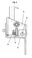
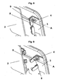
- the active head restraint 1 shown in figures 1 to 3 comprises a release mechanism for reducing the gap between an occupant's head and the head restraint in case of an accident.
- the head-engaging member 2 is mounted on a cassette comprising essentially a movable part 5 and a stationary part 3.
- the stationary part 3 is mounted on the backrest of a vehicle seat (not shown).
- the movable part 5 is connected pivotably about an across-vehicle axis A to the stationary part 3.
- the movable part 5 pivots forward and moves the attached head-engaging member 2 essentially towards an occupant's head (not shown) such that the gap between the head restraint and an occupant's head is reduced.
- a wedging body 4 connected rotatably about a vertical axis to the stationary part 3 of the cassette.
- a spring 6 the wedging body 4 is preloaded and abuts with its small width portion against the movable part 5 adjacent to the clearance between the movable part 5 and the stationary part 3 that open up upon a forward pivot movement of the movable part 5 about the cross-vehicle axis A during an activation process.
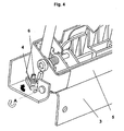
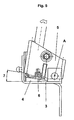
- Figures 4 and 5 show the active head restraint 1 in an activated state where the gap between an occupant's head and the head restraint is reduced by a forward pivot movement of the movable part 5 about the cross-vehicle axis A.
- a clearance in form of an angle 7 opens up.
- the clearance is filled gradually by the preloaded movable wedging body 4 that rotates about a vertical axis into the clearance and prevents the movable part 5 of the head restraint 1 from moving back.
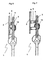
- a second embodiment of the invention is shown in figures 6 to 12 .
- the head-engaging member 2 is connected to at least one rotatable cam 8 such that the gap between an occupant's head and the head-engaging member 2 is reduced upon a concerted rotation of the cam 8 about an across-vehicle axis.
- the preloaded movable wedging body 4 is urged to move into a clearance that opens up upon rotation of the cam 8 in order to prevent the cams 8 from rotating back.
- the cam 8 comprises an extension 9 provided on the surface of the cam 8 such that the extension 9 follows a circular path away from the stationary part 3 when the cam 8 rotates about an across-vehicle axis A upon actuation of the anti-whiplash system.
- the clearance opens up between the extension 9 on the cam 8 and the stationary part 3 of the release mechanism.
- the wedging body 4 is connected rotatably about an alongside-vehicle axis to the stationary part 3.
- the wedging body 4 is preloaded and abuts with its small width portion against the extension 9 of the cam 8.
- the clearance between the extension 9 of the cam 8 and the stationary part 3 opens up upon a rotation of the cam 8 about an across-vehicle axis A during an activation process.
- the clearance is large enough to engage the small width portion of the wedging body 4 the wedging body 4 rotates about an alongside-vehicle axis such that it fills the clearance and prevents the cam 8 from moving back.
- the cam 8 has reached the activated position as shown in figures 7 , 9 , 11 and 12 the clearance is maximally opened up and the wedging body 4 has reached its final blocking position.
Landscapes
- Engineering & Computer Science (AREA)
- Aviation & Aerospace Engineering (AREA)
- Transportation (AREA)
- Mechanical Engineering (AREA)
- Seats For Vehicles (AREA)
Claims (8)
- Anti-Schleudertrauma-System zur Verwendung in Fahrzeugsitzen mit einer Kopfstütze (1), die an der Rücklehne eines Fahrzeugsitzes montiert ist, wobei die Kopfstütze (1) einen Auslösemechanismus (2, 3, 5; 2, 3, 8) zum Reduzieren des Zwischenraums zwischen dem Kopf eines Insassen und der Kopfstütze im Falle eines Unfalls aufweist, wobei der Auslösemechanismus ein bewegliches Teil (5; 2, 8) und ein ortsfestes Teil (3) aufweist, wobei ein Zwischenraum zwischen dem beweglichen Teil (5; 2, 8) und dem ortsfesten Teil (3) sich zunehmend öffnet, wenn der Auslösemechanismus ausgelöst wird,
dadurch gekennzeichnet, dass
zusätzlich zu dem Auslösemechanismus ein Keilkörper (4) mit einem Bereich kleiner Breite und einem Bereich großer Breite und einem dazwischen liegenden Bereich ansteigender Breite vorgesehen ist, wobei der Keilkörper (4) mit seinem Bereich kleiner Breite auf den Freiraum zwischen dem beweglichen Teil (5; 2, 8) und dem ortsfesten Teil (3) gerichtet ist, und dass der Keilkörper (4) beweglich ist und vorgespannt ist, um sich in den Freiraum zu bewegen, soweit sich dieser öffnet, um dadurch an dem beweglichen Teil (5; 2, 8) und an dem ortsfesten Teil (3) anzuliegen, um zu verhindern, dass das bewegliche Teil (5; 2, 8) der Kopfstütze (1) sich wieder zurückbewegt. - Anti-Schleudertrauma-System nach Anspruch 1, wobei der Keilkörper (4) durch eine Feder (6) vorgespannt ist.
- Anti-Schleudertrauma-System nach Anspruch 1 oder 2, wobei der Keilkörper (4) ein im Wesentlichen keilförmiger Körper ist.
- Anti-Schleudertrauma-System nach einem der vorhergehenden Ansprüche, wobei der Keilkörper (4) drehbar ist und einen helixförmigen Oberflächenabschnitt aufweist, der von dem Bereich mit kleiner Breite über den dazwischen liegenden Bereich ansteigender Breite zu dem Bereich großer Breite ansteigt.
- Anti-Schleudertrauma-System nach Anspruch 4, wobei der Keilkörper (4) dazu gezwungen wird, sich fortschreitend in den Freiraum zu drehen, wenn der Auslösemechanismus ausgelöst wird, um zu verhindern, dass das bewegliche Teil (2, 5) der Kopfstütze (1) sich zurückbewegt.
- Anti-Schleudertrauma-System nach einem der vorhergehenden Ansprüche, wobei der Auslösemechanismus dazu ausgestaltet ist, das bewegliche Teil (2, 5) der Kopfstütze (1) nach vorne in Bezug auf die Rücklehne des Fahrzeugsitzes zu schwenken, so dass ein winkelförmiger Freiraum (7) zwischen dem beweglichen Teil (2, 5) und dem ortsfesten Teil (3) nahe der Schwenkachse (A) geöffnet wird, wenn der Auslösemechanismus ausgelöst wird, und der bewegliche Keilkörper (4) dazu gezwungen wird, sich in den winkelförmigen Freiraum (7) zu bewegen.
- Anti-Schleudertrauma-System nach einem der vorhergehenden Ansprüche 1 bis 5, wobei das bewegliche Teil (2, 8) ein Kopfanlageteil (2) und wenigstens einen drehbaren Nocken (8) aufweist, der an dem Kopfanlageteil (2) befestigt ist, wobei der drehbare Nocken (8) ebenfalls drehbar an dem ortsfesten Teil (3) angebracht ist, so dass die Lücke zwischen dem Kopfanlageteil (2) und dem ortsfesten Teil (3) sich bei Drehung des Nockens (8) vergrößert, wobei der Nocken (8) eine Verlängerung (9) aufweist, so dass die Verlängerung (9) einem kreisförmigen Weg weg von dem ortsfesten Teil (3) folgt, wenn sich der Nocken (8) dreht, so dass der Freiraum zwischen der Verlängerung (9) des Nockens (8) und dem ortsfesten Teil (3) sich öffnet, und wobei der bewegliche Keilkörper (4) vorgespannt ist, um sich in den Freiraum zu bewegen, sobald sich dieser öffnet, um dadurch an der Verlängerung (9) des Nockens (8) und an dem ortsfesten Teil (3) anzuliegen, um zu verhindern, dass das bewegliche Teil (5) der Kopfstütze sich wieder zurückbewegt.
- Anti-Schleudertrauma-System nach einem der vorhergehenden Ansprüche, wobei der Auslösemechanismus einen Rückkehrmechanismus (10) zum Zurückführen der Kopfstütze in ihre Ausgangsposition, nachdem der Auslösemechanismus ausgelöst worden ist, ausweist, wobei der Rückkehrmechanismus Einrichtungen zum Zurückführen des beweglichen Keilkörpers zurück in seine vorgespannte Ausgangsposition aufweist.
Applications Claiming Priority (1)
| Application Number | Priority Date | Filing Date | Title |
|---|---|---|---|
| PCT/IB2007/002614 WO2009027761A1 (en) | 2007-08-29 | 2007-08-29 | Anti-whiplash backdrive system |
Publications (3)
| Publication Number | Publication Date |
|---|---|
| EP2181017A1 EP2181017A1 (de) | 2010-05-05 |
| EP2181017A4 EP2181017A4 (de) | 2011-07-27 |
| EP2181017B1 true EP2181017B1 (de) | 2012-06-06 |
Family
ID=38973155
Family Applications (1)
| Application Number | Title | Priority Date | Filing Date |
|---|---|---|---|
| EP07804901A Not-in-force EP2181017B1 (de) | 2007-08-29 | 2007-08-29 | Antischleudertraumarückstellsystem |
Country Status (3)
| Country | Link |
|---|---|
| US (1) | US8360520B2 (de) |
| EP (1) | EP2181017B1 (de) |
| WO (1) | WO2009027761A1 (de) |
Families Citing this family (2)
| Publication number | Priority date | Publication date | Assignee | Title |
|---|---|---|---|---|
| GB2566060B (en) * | 2017-09-01 | 2020-04-01 | Jaguar Land Rover Ltd | Head restraint apparatus for a vehicle and method |
| US11987158B2 (en) * | 2022-07-05 | 2024-05-21 | GM Global Technology Operations LLC | Energy absorbing headrest for a vehicle |
Family Cites Families (15)
| Publication number | Priority date | Publication date | Assignee | Title |
|---|---|---|---|---|
| DE29603467U1 (de) * | 1996-02-26 | 1996-06-20 | Trw Occupant Restraint Systems Gmbh, 73551 Alfdorf | Fahrzeugsitz |
| DE10004766B4 (de) | 2000-02-03 | 2004-10-28 | Keiper Gmbh & Co. Kg | Kopfstütze für einen Fahrzeugsitz |
| DE10215137B4 (de) * | 2002-02-05 | 2007-11-08 | Johnson Controls Gmbh | Kopfstütze für einen Fahrzeugsitz |
| DE10208620C1 (de) * | 2002-02-27 | 2003-07-24 | Itw Automotive Prod Gmbh & Co | Kopfstütze für Automobilsitze |
| KR20040104993A (ko) * | 2003-06-03 | 2004-12-14 | 현대자동차주식회사 | 액티브 헤드레스트 |
| US6749256B1 (en) * | 2003-09-08 | 2004-06-15 | Lear Corporation | Vehicle seat having a movable head restraint |
| DE10355773B3 (de) * | 2003-11-26 | 2005-01-20 | Grammer Ag | Kopfstütze für Kraftfahrzeugsitze |
| DE102004016474B3 (de) * | 2004-03-31 | 2005-08-11 | Johnson Controls Gmbh | Kopfstütze, insbesondere für ein Kraftfahrzeug |
| DE102004035583B4 (de) * | 2004-07-22 | 2008-10-02 | Keiper Gmbh & Co.Kg | Crashaktive Kopfstütze |
| DE102004059237B3 (de) * | 2004-12-08 | 2006-02-23 | Grammer Ag | Kopfstütze für Fahrzeugsitze |
| GB2424363B (en) * | 2005-03-24 | 2008-07-16 | Autoliv Dev | Active headrest with lock mechanism |
| JP2006327406A (ja) * | 2005-05-26 | 2006-12-07 | Nissan Motor Co Ltd | 車両用シートおよびそのシートによる乗員の背部支持方法 |
| GB2433429A (en) * | 2005-12-21 | 2007-06-27 | Nissan Technical Ct Europ Ltd | Vehicle seat with active head restraint apparatus |
| US20070246989A1 (en) * | 2006-04-21 | 2007-10-25 | Brockman Mark A | Adjustable headrest |
| JP2008074265A (ja) * | 2006-09-21 | 2008-04-03 | Aisin Seiki Co Ltd | 車両用シート |
-
2007
- 2007-08-29 EP EP07804901A patent/EP2181017B1/de not_active Not-in-force
- 2007-08-29 US US12/675,680 patent/US8360520B2/en not_active Expired - Fee Related
- 2007-08-29 WO PCT/IB2007/002614 patent/WO2009027761A1/en not_active Ceased
Also Published As
| Publication number | Publication date |
|---|---|
| US8360520B2 (en) | 2013-01-29 |
| EP2181017A1 (de) | 2010-05-05 |
| US20110049947A1 (en) | 2011-03-03 |
| WO2009027761A1 (en) | 2009-03-05 |
| EP2181017A4 (de) | 2011-07-27 |
Similar Documents
| Publication | Publication Date | Title |
|---|---|---|
| JP5107288B2 (ja) | ヒンジ機構およびそのような機構を備える車両用シート | |
| US5681086A (en) | Articulation for vehicle seat, and vehicle seat equipped with such an articulation | |
| US6325458B1 (en) | Pivot mechanism for a vehicle seat and seat fitted with said mechanism | |
| US7185950B2 (en) | Head restraint system | |
| KR101367313B1 (ko) | 차량 시트 | |
| EP2293960B1 (de) | Scheibenneigungsversteller mit integralen bewegungsanschlägen | |
| JP2005529783A (ja) | ヘッド/ネックレスト一体型シートアセンブリ | |
| CA2554613A1 (en) | Multi-position headrest for vehicle seat | |
| KR101438062B1 (ko) | 특히 자동차용, 헤드 지지대 | |
| US6983989B1 (en) | Linear adjustable active head restraint | |
| US20110272977A1 (en) | Head rest for a vehicle | |
| JP2003210269A (ja) | 車両座席用ヒンジ機構及びそのようなヒンジ機構を取り付けた座席 | |
| JP3983232B2 (ja) | 正面衝突したときに座席背もたれをブロックするためのブロッキング手段と蝶番で止められた背もたれとを有する車両の座席 | |
| JP2009132314A (ja) | 後席乗員保護装置 | |
| KR20130039756A (ko) | 특히, 자동차용 머리 받침대 | |
| EP2181020B1 (de) | Fahrzeugsitz mit einer verstaubaren kopfstütze und einem antischleudertraumasystem | |
| EP2181017B1 (de) | Antischleudertraumarückstellsystem | |
| EP3243695B1 (de) | Fahrzeugsitz | |
| JP2006503746A (ja) | 車両座席の、特に回動可能な要素のための、移動制限装置 | |
| JP4194578B2 (ja) | 車両の座席の関節機構及びかかる関節機構が備わった車両の座席 | |
| US20070284919A1 (en) | Vehicle Seat With Pivotable Flap | |
| CN112937396B (zh) | 致动式后排中央头枕 | |
| CN215244453U (zh) | 载具座椅 | |
| WO2023104847A1 (en) | A tiltable head restraint | |
| CN118369247A (zh) | 用于快速旋转车辆座椅组件的装置 |
Legal Events
| Date | Code | Title | Description |
|---|---|---|---|
| PUAI | Public reference made under article 153(3) epc to a published international application that has entered the european phase |
Free format text: ORIGINAL CODE: 0009012 |
|
| 17P | Request for examination filed |
Effective date: 20100208 |
|
| AK | Designated contracting states |
Kind code of ref document: A1 Designated state(s): AT BE BG CH CY CZ DE DK EE ES FI FR GB GR HU IE IS IT LI LT LU LV MC MT NL PL PT RO SE SI SK TR |
|
| AX | Request for extension of the european patent |
Extension state: AL BA HR MK RS |
|
| DAX | Request for extension of the european patent (deleted) | ||
| REG | Reference to a national code |
Ref country code: DE Ref legal event code: R079 Ref document number: 602007023193 Country of ref document: DE Free format text: PREVIOUS MAIN CLASS: B60N0002427000 Ipc: B60N0002480000 |
|
| A4 | Supplementary search report drawn up and despatched |
Effective date: 20110628 |
|
| RIC1 | Information provided on ipc code assigned before grant |
Ipc: B60N 2/48 20060101AFI20110621BHEP |
|
| RTI1 | Title (correction) |
Free format text: ANTI-WHIPLASH BACKDRIVE PREVENTION SYSTEM |
|
| GRAP | Despatch of communication of intention to grant a patent |
Free format text: ORIGINAL CODE: EPIDOSNIGR1 |
|
| GRAS | Grant fee paid |
Free format text: ORIGINAL CODE: EPIDOSNIGR3 |
|
| GRAA | (expected) grant |
Free format text: ORIGINAL CODE: 0009210 |
|
| AK | Designated contracting states |
Kind code of ref document: B1 Designated state(s): AT BE BG CH CY CZ DE DK EE ES FI FR GB GR HU IE IS IT LI LT LU LV MC MT NL PL PT RO SE SI SK TR |
|
| REG | Reference to a national code |
Ref country code: GB Ref legal event code: FG4D |
|
| REG | Reference to a national code |
Ref country code: AT Ref legal event code: REF Ref document number: 560848 Country of ref document: AT Kind code of ref document: T Effective date: 20120615 Ref country code: CH Ref legal event code: EP |
|
| REG | Reference to a national code |
Ref country code: IE Ref legal event code: FG4D |
|
| REG | Reference to a national code |
Ref country code: DE Ref legal event code: R096 Ref document number: 602007023193 Country of ref document: DE Effective date: 20120802 |
|
| REG | Reference to a national code |
Ref country code: NL Ref legal event code: VDEP Effective date: 20120606 |
|
| PG25 | Lapsed in a contracting state [announced via postgrant information from national office to epo] |
Ref country code: SE Free format text: LAPSE BECAUSE OF FAILURE TO SUBMIT A TRANSLATION OF THE DESCRIPTION OR TO PAY THE FEE WITHIN THE PRESCRIBED TIME-LIMIT Effective date: 20120606 Ref country code: LT Free format text: LAPSE BECAUSE OF FAILURE TO SUBMIT A TRANSLATION OF THE DESCRIPTION OR TO PAY THE FEE WITHIN THE PRESCRIBED TIME-LIMIT Effective date: 20120606 Ref country code: CY Free format text: LAPSE BECAUSE OF FAILURE TO SUBMIT A TRANSLATION OF THE DESCRIPTION OR TO PAY THE FEE WITHIN THE PRESCRIBED TIME-LIMIT Effective date: 20120606 Ref country code: FI Free format text: LAPSE BECAUSE OF FAILURE TO SUBMIT A TRANSLATION OF THE DESCRIPTION OR TO PAY THE FEE WITHIN THE PRESCRIBED TIME-LIMIT Effective date: 20120606 |
|
| REG | Reference to a national code |
Ref country code: AT Ref legal event code: MK05 Ref document number: 560848 Country of ref document: AT Kind code of ref document: T Effective date: 20120606 |
|
| REG | Reference to a national code |
Ref country code: LT Ref legal event code: MG4D Effective date: 20120606 |
|
| PG25 | Lapsed in a contracting state [announced via postgrant information from national office to epo] |
Ref country code: GR Free format text: LAPSE BECAUSE OF FAILURE TO SUBMIT A TRANSLATION OF THE DESCRIPTION OR TO PAY THE FEE WITHIN THE PRESCRIBED TIME-LIMIT Effective date: 20120907 Ref country code: LV Free format text: LAPSE BECAUSE OF FAILURE TO SUBMIT A TRANSLATION OF THE DESCRIPTION OR TO PAY THE FEE WITHIN THE PRESCRIBED TIME-LIMIT Effective date: 20120606 Ref country code: SI Free format text: LAPSE BECAUSE OF FAILURE TO SUBMIT A TRANSLATION OF THE DESCRIPTION OR TO PAY THE FEE WITHIN THE PRESCRIBED TIME-LIMIT Effective date: 20120606 |
|
| PG25 | Lapsed in a contracting state [announced via postgrant information from national office to epo] |
Ref country code: RO Free format text: LAPSE BECAUSE OF FAILURE TO SUBMIT A TRANSLATION OF THE DESCRIPTION OR TO PAY THE FEE WITHIN THE PRESCRIBED TIME-LIMIT Effective date: 20120606 Ref country code: SK Free format text: LAPSE BECAUSE OF FAILURE TO SUBMIT A TRANSLATION OF THE DESCRIPTION OR TO PAY THE FEE WITHIN THE PRESCRIBED TIME-LIMIT Effective date: 20120606 Ref country code: CZ Free format text: LAPSE BECAUSE OF FAILURE TO SUBMIT A TRANSLATION OF THE DESCRIPTION OR TO PAY THE FEE WITHIN THE PRESCRIBED TIME-LIMIT Effective date: 20120606 Ref country code: NL Free format text: LAPSE BECAUSE OF FAILURE TO SUBMIT A TRANSLATION OF THE DESCRIPTION OR TO PAY THE FEE WITHIN THE PRESCRIBED TIME-LIMIT Effective date: 20120606 Ref country code: AT Free format text: LAPSE BECAUSE OF FAILURE TO SUBMIT A TRANSLATION OF THE DESCRIPTION OR TO PAY THE FEE WITHIN THE PRESCRIBED TIME-LIMIT Effective date: 20120606 Ref country code: BE Free format text: LAPSE BECAUSE OF FAILURE TO SUBMIT A TRANSLATION OF THE DESCRIPTION OR TO PAY THE FEE WITHIN THE PRESCRIBED TIME-LIMIT Effective date: 20120606 Ref country code: IS Free format text: LAPSE BECAUSE OF FAILURE TO SUBMIT A TRANSLATION OF THE DESCRIPTION OR TO PAY THE FEE WITHIN THE PRESCRIBED TIME-LIMIT Effective date: 20121006 Ref country code: EE Free format text: LAPSE BECAUSE OF FAILURE TO SUBMIT A TRANSLATION OF THE DESCRIPTION OR TO PAY THE FEE WITHIN THE PRESCRIBED TIME-LIMIT Effective date: 20120606 |
|
| PG25 | Lapsed in a contracting state [announced via postgrant information from national office to epo] |
Ref country code: PL Free format text: LAPSE BECAUSE OF FAILURE TO SUBMIT A TRANSLATION OF THE DESCRIPTION OR TO PAY THE FEE WITHIN THE PRESCRIBED TIME-LIMIT Effective date: 20120606 Ref country code: PT Free format text: LAPSE BECAUSE OF FAILURE TO SUBMIT A TRANSLATION OF THE DESCRIPTION OR TO PAY THE FEE WITHIN THE PRESCRIBED TIME-LIMIT Effective date: 20121008 |
|
| REG | Reference to a national code |
Ref country code: CH Ref legal event code: PL |
|
| PG25 | Lapsed in a contracting state [announced via postgrant information from national office to epo] |
Ref country code: MC Free format text: LAPSE BECAUSE OF NON-PAYMENT OF DUE FEES Effective date: 20120831 |
|
| PLBE | No opposition filed within time limit |
Free format text: ORIGINAL CODE: 0009261 |
|
| STAA | Information on the status of an ep patent application or granted ep patent |
Free format text: STATUS: NO OPPOSITION FILED WITHIN TIME LIMIT |
|
| PG25 | Lapsed in a contracting state [announced via postgrant information from national office to epo] |
Ref country code: LI Free format text: LAPSE BECAUSE OF NON-PAYMENT OF DUE FEES Effective date: 20120831 Ref country code: ES Free format text: LAPSE BECAUSE OF FAILURE TO SUBMIT A TRANSLATION OF THE DESCRIPTION OR TO PAY THE FEE WITHIN THE PRESCRIBED TIME-LIMIT Effective date: 20120917 Ref country code: CH Free format text: LAPSE BECAUSE OF NON-PAYMENT OF DUE FEES Effective date: 20120831 Ref country code: DK Free format text: LAPSE BECAUSE OF FAILURE TO SUBMIT A TRANSLATION OF THE DESCRIPTION OR TO PAY THE FEE WITHIN THE PRESCRIBED TIME-LIMIT Effective date: 20120606 |
|
| 26N | No opposition filed |
Effective date: 20130307 |
|
| REG | Reference to a national code |
Ref country code: IE Ref legal event code: MM4A |
|
| REG | Reference to a national code |
Ref country code: DE Ref legal event code: R097 Ref document number: 602007023193 Country of ref document: DE Effective date: 20130307 |
|
| PG25 | Lapsed in a contracting state [announced via postgrant information from national office to epo] |
Ref country code: BG Free format text: LAPSE BECAUSE OF FAILURE TO SUBMIT A TRANSLATION OF THE DESCRIPTION OR TO PAY THE FEE WITHIN THE PRESCRIBED TIME-LIMIT Effective date: 20120906 Ref country code: IE Free format text: LAPSE BECAUSE OF NON-PAYMENT OF DUE FEES Effective date: 20120829 |
|
| PG25 | Lapsed in a contracting state [announced via postgrant information from national office to epo] |
Ref country code: MT Free format text: LAPSE BECAUSE OF FAILURE TO SUBMIT A TRANSLATION OF THE DESCRIPTION OR TO PAY THE FEE WITHIN THE PRESCRIBED TIME-LIMIT Effective date: 20120606 |
|
| PG25 | Lapsed in a contracting state [announced via postgrant information from national office to epo] |
Ref country code: TR Free format text: LAPSE BECAUSE OF FAILURE TO SUBMIT A TRANSLATION OF THE DESCRIPTION OR TO PAY THE FEE WITHIN THE PRESCRIBED TIME-LIMIT Effective date: 20120606 |
|
| PG25 | Lapsed in a contracting state [announced via postgrant information from national office to epo] |
Ref country code: LU Free format text: LAPSE BECAUSE OF NON-PAYMENT OF DUE FEES Effective date: 20120829 |
|
| PG25 | Lapsed in a contracting state [announced via postgrant information from national office to epo] |
Ref country code: HU Free format text: LAPSE BECAUSE OF FAILURE TO SUBMIT A TRANSLATION OF THE DESCRIPTION OR TO PAY THE FEE WITHIN THE PRESCRIBED TIME-LIMIT Effective date: 20070829 |
|
| PGFP | Annual fee paid to national office [announced via postgrant information from national office to epo] |
Ref country code: DE Payment date: 20140827 Year of fee payment: 8 |
|
| PGFP | Annual fee paid to national office [announced via postgrant information from national office to epo] |
Ref country code: FR Payment date: 20140808 Year of fee payment: 8 Ref country code: GB Payment date: 20140827 Year of fee payment: 8 |
|
| PGFP | Annual fee paid to national office [announced via postgrant information from national office to epo] |
Ref country code: IT Payment date: 20140820 Year of fee payment: 8 |
|
| REG | Reference to a national code |
Ref country code: DE Ref legal event code: R119 Ref document number: 602007023193 Country of ref document: DE |
|
| GBPC | Gb: european patent ceased through non-payment of renewal fee |
Effective date: 20150829 |
|
| PG25 | Lapsed in a contracting state [announced via postgrant information from national office to epo] |
Ref country code: IT Free format text: LAPSE BECAUSE OF NON-PAYMENT OF DUE FEES Effective date: 20150829 |
|
| REG | Reference to a national code |
Ref country code: FR Ref legal event code: ST Effective date: 20160429 |
|
| PG25 | Lapsed in a contracting state [announced via postgrant information from national office to epo] |
Ref country code: DE Free format text: LAPSE BECAUSE OF NON-PAYMENT OF DUE FEES Effective date: 20160301 Ref country code: GB Free format text: LAPSE BECAUSE OF NON-PAYMENT OF DUE FEES Effective date: 20150829 |
|
| PG25 | Lapsed in a contracting state [announced via postgrant information from national office to epo] |
Ref country code: FR Free format text: LAPSE BECAUSE OF NON-PAYMENT OF DUE FEES Effective date: 20150831 |