EP2181368B1 - Dispositif de programmation pour un réseau constitué de noeuds de commande et installation équipée d'un tel dispositif de programmation - Google Patents
Dispositif de programmation pour un réseau constitué de noeuds de commande et installation équipée d'un tel dispositif de programmation Download PDFInfo
- Publication number
- EP2181368B1 EP2181368B1 EP08803094A EP08803094A EP2181368B1 EP 2181368 B1 EP2181368 B1 EP 2181368B1 EP 08803094 A EP08803094 A EP 08803094A EP 08803094 A EP08803094 A EP 08803094A EP 2181368 B1 EP2181368 B1 EP 2181368B1
- Authority
- EP
- European Patent Office
- Prior art keywords
- module
- control
- control node
- programming device
- network
- Prior art date
- Legal status (The legal status is an assumption and is not a legal conclusion. Google has not performed a legal analysis and makes no representation as to the accuracy of the status listed.)
- Active
Links
Images




Classifications
-
- G—PHYSICS
- G05—CONTROLLING; REGULATING
- G05B—CONTROL OR REGULATING SYSTEMS IN GENERAL; FUNCTIONAL ELEMENTS OF SUCH SYSTEMS; MONITORING OR TESTING ARRANGEMENTS FOR SUCH SYSTEMS OR ELEMENTS
- G05B19/00—Program-control systems
- G05B19/02—Program-control systems electric
- G05B19/04—Program control other than numerical control, i.e. in sequence controllers or logic controllers
- G05B19/042—Program control other than numerical control, i.e. in sequence controllers or logic controllers using digital processors
- G05B19/0421—Multiprocessor system
-
- G—PHYSICS
- G05—CONTROLLING; REGULATING
- G05B—CONTROL OR REGULATING SYSTEMS IN GENERAL; FUNCTIONAL ELEMENTS OF SUCH SYSTEMS; MONITORING OR TESTING ARRANGEMENTS FOR SUCH SYSTEMS OR ELEMENTS
- G05B19/00—Program-control systems
- G05B19/02—Program-control systems electric
- G05B19/418—Total factory control, i.e. centrally controlling a plurality of machines, e.g. direct or distributed numerical control [DNC], flexible manufacturing systems [FMS], integrated manufacturing systems [IMS] or computer integrated manufacturing [CIM]
- G05B19/41845—Total factory control, i.e. centrally controlling a plurality of machines, e.g. direct or distributed numerical control [DNC], flexible manufacturing systems [FMS], integrated manufacturing systems [IMS] or computer integrated manufacturing [CIM] characterised by system universality, reconfigurability, modularity
-
- H—ELECTRICITY
- H04—ELECTRIC COMMUNICATION TECHNIQUE
- H04L—TRANSMISSION OF DIGITAL INFORMATION, e.g. TELEGRAPHIC COMMUNICATION
- H04L41/00—Arrangements for maintenance, administration or management of data switching networks, e.g. of packet switching networks
- H04L41/08—Configuration management of networks or network elements
- H04L41/0803—Configuration setting
-
- G—PHYSICS
- G05—CONTROLLING; REGULATING
- G05B—CONTROL OR REGULATING SYSTEMS IN GENERAL; FUNCTIONAL ELEMENTS OF SUCH SYSTEMS; MONITORING OR TESTING ARRANGEMENTS FOR SUCH SYSTEMS OR ELEMENTS
- G05B2219/00—Program-control systems
- G05B2219/20—Pc systems
- G05B2219/21—Pc I-O input output
- G05B2219/21081—At start up, check I-O configuration and store addresses in ram
-
- G—PHYSICS
- G05—CONTROLLING; REGULATING
- G05B—CONTROL OR REGULATING SYSTEMS IN GENERAL; FUNCTIONAL ELEMENTS OF SUCH SYSTEMS; MONITORING OR TESTING ARRANGEMENTS FOR SUCH SYSTEMS OR ELEMENTS
- G05B2219/00—Program-control systems
- G05B2219/20—Pc systems
- G05B2219/25—Pc structure of the system
- G05B2219/25062—Detect physical location of field device
-
- G—PHYSICS
- G05—CONTROLLING; REGULATING
- G05B—CONTROL OR REGULATING SYSTEMS IN GENERAL; FUNCTIONAL ELEMENTS OF SUCH SYSTEMS; MONITORING OR TESTING ARRANGEMENTS FOR SUCH SYSTEMS OR ELEMENTS
- G05B2219/00—Program-control systems
- G05B2219/20—Pc systems
- G05B2219/25—Pc structure of the system
- G05B2219/25093—During start, integration into machine, send module functionality to scheduler
-
- G—PHYSICS
- G05—CONTROLLING; REGULATING
- G05B—CONTROL OR REGULATING SYSTEMS IN GENERAL; FUNCTIONAL ELEMENTS OF SUCH SYSTEMS; MONITORING OR TESTING ARRANGEMENTS FOR SUCH SYSTEMS OR ELEMENTS
- G05B2219/00—Program-control systems
- G05B2219/20—Pc systems
- G05B2219/25—Pc structure of the system
- G05B2219/25096—Detect addresses of connected I-O, modules
-
- Y—GENERAL TAGGING OF NEW TECHNOLOGICAL DEVELOPMENTS; GENERAL TAGGING OF CROSS-SECTIONAL TECHNOLOGIES SPANNING OVER SEVERAL SECTIONS OF THE IPC; TECHNICAL SUBJECTS COVERED BY FORMER USPC CROSS-REFERENCE ART COLLECTIONS [XRACs] AND DIGESTS
- Y02—TECHNOLOGIES OR APPLICATIONS FOR MITIGATION OR ADAPTATION AGAINST CLIMATE CHANGE
- Y02P—CLIMATE CHANGE MITIGATION TECHNOLOGIES IN THE PRODUCTION OR PROCESSING OF GOODS
- Y02P90/00—Enabling technologies with a potential contribution to greenhouse gas [GHG] emissions mitigation
- Y02P90/02—Total factory control, e.g. smart factories, flexible manufacturing systems [FMS] or integrated manufacturing systems [IMS]
Definitions
- the invention relates to a programming device for a network of control nodes and a system with such a programming device.
- the control task to be executed is geographically and functionally optimally distributed to the control nodes of the decentralized control.
- the control nodes communicate with each other and with the higher-level systems via industrial local networks. Due to the decentralized control, the communication effort can be reduced since the individual control nodes themselves have to assume control tasks relating to their areas and only have to communicate with the other control nodes or with the higher-level systems for coordination.
- the decentralized control is based on the basic idea of dividing the automation task into individual functional and logically completed modules, which can then be arranged close to the process, thereby reducing the cabling and installation costs. By dividing into modules, the complexity can be reduced, so that functions can be realized more easily.
- Another trend in automation technology is open systems that allow the user to combine automation components from different manufacturers. As a result, it is possible for the user to use the best technical solution for individual subtasks and also to select the most favorable manufacturer.
- An essential requirement for the automation components in open systems is the connectivity, ie the individual automation components must be integrated into the system Be able to exchange data with each other.
- open systems require interoperability of the automation components, ie the individual automation components must have defined profiles in order to ensure cooperation during the execution of the automation task.
- the interchangeability of automation components from different manufacturers is required, ie the devices of the manufacturers must have the same range of functions.
- WO 2005/093 530 A describes a method for configuring the communication relationships between control nodes in a manufacturing plant by means of one of the control nodes, which discloses all the features of the preamble of claim 1.
- the object of the invention is to provide a programming device for a network of control nodes and a system with such a programming device, which enable flexible asset management, in particular with regard to changes in the production and manufacturing process.
- a programming device which determines the communication relationship between the control nodes in the network.
- the programming device has a detection module to detect the control node connected to the network.
- a plant object module connected to the acquisition module is provided, which contains a plant object model representing the control node configuration of the network, which defines the communication relationships between the determined control nodes.
- Connected to the system object module in the programming device is a configuration module which transmits the communication relationships between the control nodes in the network established by the system object module to the control nodes.
- the inventive design allows a decentralized control in the form of an open system with high compatibility with respect to the control nodes. Changes in the production and manufacturing process, in particular production expansion and product change can be implemented easily without much effort in the decentralized control using the programming device according to the invention, since the programming device can set the communication relationship between the individual control nodes and thus adapt to the desired production and manufacturing process ,
- the plant object module in the programming device is designed so that the communication relationships between the participants in the control node are determined on the basis of the system object module and then transmitted to the control node using the configuration module.
- the data transmission between the control nodes in the network in the form data packets that are transmitted on the network performed, wherein the control nodes are designed to convert a control node process image or other data that does not belong to the process image into data telegrams.
- This design of data traffic between the control nodes makes it possible to design the communication relationships between the control nodes simply and flexibly in order to achieve optimum adaptation to the production and production processes.
- each subscriber in the control node is designed to directly access the control node process image transmitted between the subscribers or other data which does not belong to the process image.
- This data transfer procedure ensures fast data exchange in the control node.
- Fig. 1 shows such a decentralized control with three control nodes 1A, 1B, 1C and a programming device 2 for configuring and monitoring the network.
- the control nodes 1 each have a network interface 11, which forms a physical interface to the network.
- the control node 1 and the programming device 2 are connected to each other via an industrial bus system 3, a so-called field bus.
- the essential requirement of the fieldbus system for use in process and manufacturing technology is the real-time capability, ie the fieldbus system must ensure that every data packet sent arrives at the receiver within a limited guaranteed time.
- Fig. 1 shows a control node 1A with three participants 12A, 12B, 12 C, which are connected via an internal bus system 13 to the network interface 11 of the control node.
- Each control node has a control node description representing the functional and communication characteristics of the control node.
- This control node description is standardized for all control nodes and stored as a file in a memory area 14 of the control node.
- the individual subscribers in turn, analogously to the control node, have their own subscriber description, which reproduces the communication and functional characteristics of the subscriber and as a standardized file in a memory area (not shown). the participant or in the memory area 14 of the control node is stored.
- control-technical content of the system or the hardware of the control nodes must be adapted extensively in the case of product and production process changes. This adaptation can be substantially reduced with the inventively provided program device 2 on the plant network.
- the programming device 2 which is connected via the fieldbus 3 to the control node 1 or the participants 12 in the control node, can determine the control node connected to the network or participants in the control node in a first step. On the basis of a system object model provided in the programming device 2, the programming device can then determine the communication relationships between the determined control nodes or the determined subscribers in the control node and then transmit these communication relationships to the control nodes or the subscribers in the control node.
- the structure of the programming device is shown schematically in FIG Fig. 2 shown.
- the individual components of the programming device can be embodied both in hardware and in software form.
- the programming device 2 has three interfaces: a first fieldbus interface 21 for connecting the control nodes 1 via the fieldbus 3, which is designed as a network interface, a data interface 22 and a man-machine interface 23rd
- the programming device 2 can display a plant description and a product and process description of, for example, as in Fig. 2 is shown, an engineering system 4, with which a plant design was made to manufacture a product, import.
- the plant description contains the orientation and order of the network participants in relation to the overall system and a representation of the network parameters and communication endpoints.
- the plant description and a product and process description is converted by an attached to the data interface 22 system configuration input module 24 in an object model that holds the system description and the product and process description in a standardized format.
- the programming device further comprises a device description input / output module 25, with which the programming device 2 can import or export control node or subscriber descriptions.
- the device description input / output module 25 can exchange the device and subscriber description via the data interface 22 with an external database 5 or also query via the data interface 21 from the control nodes or the participants in the control node. Furthermore, there is also the possibility that via the device description input / output module 25 updated device descriptions are stored back into the control nodes or the subscribers in the control nodes.
- the plant configuration input module 24 and the device description input / output module 25 are connected to a plant object module 26 for merging the object model containing a standardized plant, product and process description with the control node or subscriber descriptions into a plant object model.
- the asset module 26 determines the communication relationships between the control nodes 1 and subscribers 12 in the control node.
- the requirement for communication relationships in industrial automation control systems is the real-time capability, i.
- the decentralized control must react in good time to all occurring events in all operating conditions.
- the exchange of real-time data between the control nodes in the network or the participants in the control node is preferably carried out cyclically in order to ensure a fast and deterministic communication.
- non-real-time data in particular parameters that do not need to be permanently and time-critically evaluated, are instead exchanged acyclically between the control nodes or the nodes in the control node.
- the system object module 26 determines the distribution between cyclic and acyclic data exchange with the communication relationships between the control nodes 1 and subscribers 12 in the control node.
- the communication between the control nodes in the network is carried out according to the definition by the system object module 26 according to the rules of the fieldbus protocol, wherein the data to be exchanged are converted between the control node 1 into data telegrams.
- the preferred communication infrastructure in the fieldbus is the Ethernet protocol, which allows high data rates to be achieved.
- the data exchange between the participants in the control node in contrast, in order to enable a fast data transmission, determined by the asset module 26 preferably in the form of data mapping operations, each participant 12 is designed in the control node 1, a direct data access to the between the participants via the internal bus thirteenth exchanged data.
- the system object module 26 is furthermore connected to a detection module 27, with which the control node 1 or subscriber 12 connected to the network can be determined in the control node 1.
- the detection module 27 via the fieldbus interface 21 connected to the network Determine control node or participant in the control node.
- Each connected to the network control node or each participant in the control node namely has a unique address associated with it, via which it can be addressed.
- the control nodes or the participants in the control node can refer to this address, for example, optionally via the Dynamic Host Configuration Protocol (DHCP) or via AutoIP.
- DHCP Dynamic Host Configuration Protocol
- the detection module 27 can use different mechanisms.
- the detection module 27 can transmit a so-called broadcast telegram via fieldbus interface 21 to all control nodes 1 or subscribers 12 in the control node 1, which are connected to the network.
- the control nodes 1 or the subscribers 12 in the network then respond to this broadcast telegram with a response telegram in order to notify the acquisition module 27 of the address of the control node or of the subscriber in the control node.
- a network protocol for transmitting the broadcast telegram e.g. the User Datagram Protocol (UPP), which is a minimal connectionless network protocol.
- UDP User Datagram Protocol
- UPNP Universal Plug and Play Protocol
- the acquisition module 26 may also request the control nodes 1 and the participants 12 in the control node 1, the control node or subscriber description, which characterizes the network properties and the functions of the device and the control node or the participants in the control node in a standardized format stored to the device description input / output module 25 to transmit.
- control node 1 may also transmit the control node or subscriber description to the device description input / output module 25.
- the acquisition module 27 forwards the addresses of the detected control nodes or subscribers in the control node and the device description input / output module 25 forwards the control node or subscriber descriptions to the asset module 26.
- the system object module 26 compares the number of control nodes or subscribers provided in the control node according to the system object module with the detected control nodes or subscribers in the control node. If the detected control nodes or subscribers in the control node do not completely cover the control node or subscriber number provided in accordance with the system description, the system object module 26 gives e.g. via the man-machine interface 23 an error message. The further configuration process of the system by the programming device 2 is then interrupted.
- the system object module 26 can also compare the control node or subscriber descriptions read from the database 5 with the currently detected control node or subscriber descriptions and, if appropriate, update the control node or subscriber description stored in the database 5 or the control node or subscriber accordingly.
- the communication relationships between the control nodes 1 in the network determined by the asset object module 26 based on the asset model standardized by the asset configuration input module 24 and the control node or subscriber descriptions read in via the capture module 27 or the device description import / export module 25 or between the participants 12 in each control node specify each sender and receiver, the data transmission type and the data type.
- the data to be transferred are divided into product process and control parameters, event data and process data.
- Product process and control parameters are transferred acyclically before the production process for parameterization between control nodes or their subscribers. They are not real-time critical.
- Event data is used to notify application programs in the control nodes or participants in the control nodes about events.
- Such event data may be the change of a process signal, the exceeding of a threshold, an operator intervention, the occurrence of an error, etc.
- the event data is acyclically exchanged between the participants of the communication relationships and is not real-time critical.
- Process data is usually function data, e.g. Sensor data required for the process and manufacturing process and real-time critical.
- This process data is preferably cyclically exchanged between the subscribers to guarantee real-time transmission.
- the process data can also be transmitted in an acyclic way between the participants.
- Such process data, which is transmitted acyclically, are process and product parameters for the control nodes or for the participants in the control node for executing the application programs.
- the asset object module 26 also determines with the communication relationships how the data transfer has to occur. In a data transfer between the control nodes or participants in a control node on participants in another control node, the data transmission takes place according to the fieldbus protocol, wherein the system object module, the message format and in particular specifies the data structure in the telegram. The control nodes 1 then use their network connection unit 11 to convert the process data to be transmitted into these predetermined message formats.
- the data transmission from the asset module 26 is set as transparent local communication, wherein the participants in the control node then perform data mapping operations in which a direct data access of the participants is performed on the transmitted control node process image. In contrast to network transmission, it is then not necessary to copy the data into data telegrams, as a result of which particularly fast data transmission between subscribers of a local node can be achieved.
- the system object module 26 transfers the data set with the defined communication relationships to a configuration output module 28, which converts the communication relationships specified by the system object module 26 into telegrams in order to send them via the fieldbus interface 21 and the fieldbus 3 to the control nodes 1 or the subscribers 12 in FIG to transmit the control node.
- a process parameter output module 29 connected to the system object module 26 is provided in the programming device 2, which converts the process and product parameters distributed by the system object module 26 to the individual nodes or control nodes into telegrams and these via the fieldbus interface 21 and the fieldbus 3 on the control nodes 1 and the participants 12 transmits in the control node.
- the programming device 2 may also have a monitoring module 30, which is connected to the control node 1 via the fieldbus interface 21 and the field bus 3, to the status of the control nodes during machine operation or to monitor the participant in the control node and to perform an error detection, the errors can be transmitted via the fieldbus interface 21 or displayed via the man-machine interface 23.
- a monitoring module 30 which is connected to the control node 1 via the fieldbus interface 21 and the field bus 3, to the status of the control nodes during machine operation or to monitor the participant in the control node and to perform an error detection, the errors can be transmitted via the fieldbus interface 21 or displayed via the man-machine interface 23.
- the man-machine interface 23 of the programming device 2 preferably has a user interface 31 for the operator, via which preferably a complete plant, product and process description is graphically displayed.
- the control nodes or subscribers in the control node, the network topology and the network parameters, the control node and subscriber description and the process and product parameters can be displayed.
- the data sets specified by the investment object module 26 with the communication relationships can be displayed on the user interface 31. It is also possible to visualize the plant object model, the plant, product and process description, the descriptions of individual control nodes but also of the entire plant on the user interface 31.
- the user interface 31 can be designed so that the individual representations can also be changed by the operator. These inputs are then fed back to the plant object module 26 via the man-machine interface 23.
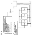
- FIG. 3A to C show different operating modes of in Fig. 1 represented decentralized control with a network of control node 1 and a programming device 2, as shown in Fig. 2 is shown in detail.
- Fig. 3A and Fig. 3B are the two initialization steps of the programming device 2, namely the detection phase and the configuration phase of the decentralized control, and in Fig. 3C the machine operation shown.
- the data exchange carried out in each case is indicated by arrows in the figures.
- the programming device 2 imports the system description, which was generated for example by means of an engineering system 5, to a certain production and manufacturing processes.
- the plant description includes the orientation and the order of the participants in the network in relation to the entire plant to carry out the desired production and manufacturing process.
- the programming device 2 reads in a process description and a product description as well as information about the network parameters and the communication end points from the engineering system.
- the programming device 2 detects the control node 1 or subscriber 12 connected to the network in the control node.
- the control nodes 1 or the subscribers 12 in the control node receive at startup on the fieldbus 3 via DHCP or by auto-IP e.g. from a server (not shown) a valid address.
- this valid address can also be previously stored in the control node or the participants in the control node.
- the control nodes or the participants in the control node transmit this address to the programming device 2 either automatically at start-up on the network or at the request of the programming device, e.g. with the help of a broadcast telegram.
- the programming device 2 also detects the subscriber characteristics.
- the control node and subscriber descriptions identify the network properties of the participants as well as their functions. These control node and subscriber descriptions are received by the programming device 2 either from an external database (not shown) or via fieldbus 3 directly from control nodes in the control node.
- the programming device 2 preferably displays the read-in information on the user interface so that the operator can make changes, for example in the control node and subscriber descriptions, the product and process parameters and the network topology and their parameters.
- the programming device 2 sets the communication parameters between the participants in the network.
- the event and data streams are defined, as well as the type of data transmission cyclically, ie real-time capable, or determined acyclically.
- the specified data record with the communication relationships K is then written by the programming device 2 via the fieldbus 3 into the control nodes or subscribers in the control node.
- the participants are given the data transmission type, the data type and the sender or receiver of the data.
- the programming device 2 transmits the process parameters P important for the individual control nodes or subscribers in the control node for carrying out the production and production process.
- the initialization steps shown then switch the network to machine operation to perform the desired production and manufacturing process.
- the programming device 2 is operated by the remote controller as in Fig. 3C shown, no longer needed.
- the programming device 2 is then either turned off or has an observational function in the production and manufacturing process, so the fault monitoring and diagnosis is used.
- the programming device can also have control computer function and be integrated into the control process.
- control nodes or the nodes in the control node autonomously exchange process and event data via the communication relationships preconfigured by the programming device 2.
- the data transmission takes place in a transparent manner Data mapping operations with a direct data access of each participant to the control node process image transmitted between the participants.
- the data transmission is carried out in accordance with the specified network protocol, the control node data being converted by the associated network connections into the network telegrams.
Landscapes
- Engineering & Computer Science (AREA)
- Physics & Mathematics (AREA)
- General Physics & Mathematics (AREA)
- Automation & Control Theory (AREA)
- Computer Networks & Wireless Communication (AREA)
- Signal Processing (AREA)
- General Engineering & Computer Science (AREA)
- Manufacturing & Machinery (AREA)
- Quality & Reliability (AREA)
- Programmable Controllers (AREA)
- Computer And Data Communications (AREA)
- Stored Programmes (AREA)
Claims (13)
- Dispositif de programmation (2) destiné à un réseau (3) constitué de noeuds de commande (1), comprenant :un module de détection (27) destiné à déterminer les noeuds de commande connectés au réseau,un module d'objet d'installation relié au module de détection (26), qui comporte un modèle d'objet d'installation représentant la configuration des noeuds de commande du réseau, dans lequel le module d'objet d'installation est apte à établir les relations de communication entre les noeuds de réseau déterminés sur la base du modèle d'objet d'installation, etun module de sortie de configuration (28) relié au module d'objet d'installation, destiné à transmettre aux noeuds de commande les relations de communication établies par le module d'objet d'installation entre les noeuds de commande du réseau,
caractérisé parun module d'entrée de configuration d'installation (24) relié au module d'objet d'installation (26), destiné à convertir une description d'installation, de produit etde processus en un modèle d'objet qui comporte la description d'installation, de produit et de processus en un format normalisé, etun module d'entrée/sortie de description d'appareil (25) relié au module d'objet d'installation (26), destiné à l'entrée et à la sortie de descriptions de noeuds de commande,dans lequel le module d'objet d'installation (26) est apte à combiner le modèle d'objet comportant la description d'installation, de produit et de processus en format normalisé, aux descriptions de noeuds de commande, en le modèle d'objet d'installation. - Dispositif de programmation selon la revendication 1, caractérisé en ce que le module d'objet d'installation (26) est apte à établir les relations de communication entre les noeuds de commande déterminés sur le réseau à partir des adresses des noeuds de commande correspondants et du type de transmission de données à utiliser.
- Dispositif de programmation selon la revendication 1 ou 2, caractérisé en ce que le module d'objet d'installation (26) est en outre apte à établir les relations de communication entre des abonnés (12) du noeud de commande (1) sur la base du modèle d'objet d'installation, et dans lequel le module de sortie de configuration (28) relié au module d'objet d'installation est apte à transmettre au noeud de commande les relations de communication établies par le module d'objet d'installation entre les abonnés du noeud de commande.
- Dispositif de programmation selon la revendication 3, caractérisé en ce que le module d'objet d'installation (26) est apte à établir les relations de communication entre les abonnés (12) du noeud de commande sur la base du modèle d'objet d'installation à partir des processus de formation d'images de données s'effectuant entre les abonnés.
- Dispositif de programmation selon l'une quelconque des revendications 1 à 4, caractérisé par un module de sortie de paramètres de processus (29) relié au module d'objet d'installation (26), destiné à fournir en sortie aux noeuds de commande (1) des paramètres de processus et de produits.
- Dispositif de programmation selon l'une quelconque des revendications 1 à 5, caractérisé par un module de surveillance (30) relié au module d'objet d'installation, destiné à surveiller les noeuds de commande (1).
- Dispositif de programmation selon l'une quelconque des revendications 1 à 6, caractérisé par un module de traitement (23, 31) destiné à représenter et/ou traiter le modèle d'objet d'installation et la description d'installation, de produit et de processus.
- Installation comprenant un réseau comportant des noeuds de commande (1) et un dispositif de programmation (2) selon l'une quelconque des revendication 1 à 7, caractérisé en ce que le dispositif de programmation est apte à établir les relations de communication entre les noeuds de commande ou dans les noeuds de commande dans le contexte d'un processus d'initialisation.
- Installation selon la revendication 8, caractérisée en ce que le module de détection (27) du dispositif de programmation (2), pour obtenir les noeuds de commande (1) connectés à l'installation, envoie sur le réseau connecté (3) un télégramme de diffusion aux noeuds de commande (1) connectés, auquel les noeuds de commande connectés au réseau répondent par un télégramme d'identification.
- Installation selon la revendication 9, caractérisée en ce que chaque noeud de commande (1) envoie un télégramme d'identification au module de détection (27) du dispositif de programmation (2) lors d'un démarrage.
- Installation selon l'une quelconque des revendications 8 à 10, caractérisée en ce que chaque noeud de commande (1) dispose d'une adresse valide qui peut être stockée de manière permanente ou être obtenue par DHCP ou par AUTO-IP et qui est transférée au dispositif de programmation (2).
- Installation selon l'une quelconque des revendications 8 à 11, caractérisée en ce que la transmission de données entre les noeuds de commande (1) du réseau s'effectue sous la forme de paquets de données qui sont transmis sur le réseau (3), dans lequel les noeuds de commande sont aptes à effectuer une transformation d'une image des processus des noeuds de commande en les télégrammes de données.
- Installation selon l'une quelconque des revendications 8 à 12, caractérisée en ce que la transmission de données entre les abonnés (12) du noeud de commande (1) s'effectue sous la forme de processus de formation d'images des données, dans lequel chaque abonné d'un noeud de commande est apte à effectuer un accès direct à l'image de processus du noeud de commande transmise entre les abonnés.
Applications Claiming Priority (2)
| Application Number | Priority Date | Filing Date | Title |
|---|---|---|---|
| DE102007039428A DE102007039428A1 (de) | 2007-08-21 | 2007-08-21 | Programmiervorrichtung für ein Netzwerk aus Steuerknoten und Anlage mit einer solchen Programmiervorrichtung |
| PCT/EP2008/060857 WO2009024576A1 (fr) | 2007-08-21 | 2008-08-19 | Dispositif de programmation pour un réseau constitué de noeuds de commande et installation équipée d'un tel dispositif de programmation |
Publications (2)
| Publication Number | Publication Date |
|---|---|
| EP2181368A1 EP2181368A1 (fr) | 2010-05-05 |
| EP2181368B1 true EP2181368B1 (fr) | 2012-12-26 |
Family
ID=40120424
Family Applications (1)
| Application Number | Title | Priority Date | Filing Date |
|---|---|---|---|
| EP08803094A Active EP2181368B1 (fr) | 2007-08-21 | 2008-08-19 | Dispositif de programmation pour un réseau constitué de noeuds de commande et installation équipée d'un tel dispositif de programmation |
Country Status (6)
| Country | Link |
|---|---|
| US (1) | US8892785B2 (fr) |
| EP (1) | EP2181368B1 (fr) |
| JP (1) | JP5084908B2 (fr) |
| CN (1) | CN101784968B (fr) |
| DE (1) | DE102007039428A1 (fr) |
| WO (1) | WO2009024576A1 (fr) |
Families Citing this family (14)
| Publication number | Priority date | Publication date | Assignee | Title |
|---|---|---|---|---|
| EP2226694A1 (fr) * | 2009-03-05 | 2010-09-08 | Siemens Aktiengesellschaft | Appareil de programmation et procédé destiné au paramétrage d'une liaison de communication entre des composants d'automatisation dans un agencement d'automatisation industriel |
| DE102009042354C5 (de) | 2009-09-23 | 2017-07-13 | Phoenix Contact Gmbh & Co. Kg | Verfahren und Vorrichtung zur sicherheitsgerichteten Kommunikation im Kommunikations-Netzwerk einer Automatisierungs-Anlage |
| DE102010040054A1 (de) * | 2010-08-31 | 2012-03-01 | Endress + Hauser Process Solutions Ag | Verfahren zur Sicherstellung der korrekten Funktionsweise einer Automatisierungsanlage |
| US9304963B2 (en) * | 2011-01-14 | 2016-04-05 | Rockwell Automation Technologies, Inc. | Data table structure for self-organized management of communication with functional modules coupled via backplane assembly based on received module description including control logic |
| EP2557464B1 (fr) * | 2011-08-12 | 2015-07-29 | Siemens Aktiengesellschaft | Procédé destiné au fonctionnement d'un système d'automatisation |
| DE102011121522A1 (de) * | 2011-12-16 | 2013-06-20 | Robert Bosch Gmbh | Verfahren zum Steuern einer Anlage mit Echtzeitübertragung von Datentelegrammen |
| DE102012102187C5 (de) * | 2012-03-15 | 2016-11-03 | Phoenix Contact Gmbh & Co. Kg | Steuerungsvorrichtung zum Steuern von sicherheitskritischen Prozessen in einer automatisierten Anlage und Verfahren zur Parametrierung der Steuerungsvorrichtung |
| DE102012011216A1 (de) * | 2012-06-06 | 2013-12-12 | Rwe Innogy Gmbh | Steuerung eines windenergiesystems |
| DE202013100498U1 (de) * | 2013-02-04 | 2014-05-06 | Aumüller Aumatic GmbH | Antriebssystem |
| DE102014202071A1 (de) * | 2014-02-05 | 2015-08-06 | Robert Bosch Gmbh | Verfahren und Einrichtung zum Betrieb eines Kommunikationsnetzwerks insbesondere eines Kraftfahrzeugs |
| US10320958B2 (en) * | 2014-12-19 | 2019-06-11 | Emerson Process Management Lllp | Fast data transfer communication protocol for an industrial process network |
| AT520270B1 (de) | 2017-07-28 | 2021-01-15 | Wittmann Kunststoffgeraete | Verfahren zum Verwalten und Steuern von Produktionsmitteln mit einer oder |
| DE102018129813A1 (de) * | 2018-11-26 | 2020-05-28 | Beckhoff Automation Gmbh | Datenübertragungsverfahren und Automatisierungskommunikationsnetzwerk |
| EP3805878B1 (fr) * | 2019-10-11 | 2022-06-15 | Siemens Aktiengesellschaft | Procédé de visualisation de contenu d'écran sur un système de visualisation de données ainsi que système de visualisation de données destiné à la visualisation du contenu de l'écran |
Family Cites Families (19)
| Publication number | Priority date | Publication date | Assignee | Title |
|---|---|---|---|---|
| DE2842372A1 (de) | 1978-09-28 | 1980-04-10 | Siemens Ag | Speicherprogrammierbare steuerung |
| JPH08110878A (ja) * | 1994-10-11 | 1996-04-30 | Mitsubishi Electric Corp | ネットワークシステム |
| US5771339A (en) * | 1995-06-07 | 1998-06-23 | Xerox Corporation | Method for automatically deriving print engine capabilities for incremental scheduling from compositional print engine models |
| US6098116A (en) | 1996-04-12 | 2000-08-01 | Fisher-Rosemont Systems, Inc. | Process control system including a method and apparatus for automatically sensing the connection of devices to a network |
| US6826590B1 (en) * | 1996-08-23 | 2004-11-30 | Fieldbus Foundation | Block-oriented control system on high speed ethernet |
| US5978850A (en) * | 1997-07-02 | 1999-11-02 | National Instruments Corporation | System and method for accessing parameters in a fieldbus network using a tag parameters interface |
| US5923557A (en) * | 1997-08-01 | 1999-07-13 | Hewlett-Packard Company | Method and apparatus for providing a standard interface to process control devices that are adapted to differing field-bus protocols |
| US6574234B1 (en) * | 1997-09-05 | 2003-06-03 | Amx Corporation | Method and apparatus for controlling network devices |
| HK1047204B (en) * | 1999-06-21 | 2011-11-04 | Fieldbus Foundation | Block-oriented control system on high speed ethernet |
| US6711629B1 (en) * | 1999-10-18 | 2004-03-23 | Fisher-Rosemount Systems, Inc. | Transparent support of remote I/O in a process control system |
| EP1298506A1 (fr) * | 2001-09-27 | 2003-04-02 | Siemens Aktiengesellschaft | Accès dynamique aux ressources d'automatisation |
| DE10151116A1 (de) * | 2001-10-15 | 2003-05-08 | Siemens Ag | Verfahren zur Inbetriebnahme eines Bedien- und Beobachtungssystems von Feldgeräten |
| US7849171B2 (en) * | 2002-02-27 | 2010-12-07 | Ricoh Co. Ltd. | Method and apparatus for monitoring remote devices by creating device objects for the monitored devices |
| DE10254010B4 (de) | 2002-11-19 | 2009-01-02 | Siemens Ag | Verfahren zur automatischen Konfiguration einer Parametrieroberfläche von Werkzeugmaschinen oder Produktionsmaschinen |
| DE102004015240A1 (de) * | 2004-03-29 | 2005-10-27 | Siemens Ag | Modulare Maschine und entsprechendes Verfahren zum dynamischen Konfigurieren der Topologie dieser Maschine |
| DE102004060301A1 (de) * | 2004-12-15 | 2006-06-22 | Robert Bosch Gmbh | Verfahren zum Initialisieren eines elektronischen Systems umfassend mehrere Plug-Ins |
| DE102005034944B3 (de) * | 2005-07-22 | 2006-11-09 | Siemens Ag | Verfahren und Anordnung zur automatischen Konfiguration eines Master-Slave-Feldbussystems |
| DE102005051769A1 (de) * | 2005-10-27 | 2007-05-03 | Endress + Hauser Flowtec Ag | Vorrichtung zum Betreiben einer Prozessanlage |
| DE102006027012A1 (de) * | 2006-06-08 | 2007-12-13 | Endress + Hauser Process Solutions Ag | Verfahren zum Austausch eines Feldgerätes der Automatisierungstechnik |
-
2007
- 2007-08-21 DE DE102007039428A patent/DE102007039428A1/de not_active Withdrawn
-
2008
- 2008-08-19 JP JP2010521415A patent/JP5084908B2/ja not_active Expired - Fee Related
- 2008-08-19 EP EP08803094A patent/EP2181368B1/fr active Active
- 2008-08-19 CN CN200880103816XA patent/CN101784968B/zh active Active
- 2008-08-19 WO PCT/EP2008/060857 patent/WO2009024576A1/fr not_active Ceased
-
2010
- 2010-02-18 US US12/707,960 patent/US8892785B2/en active Active
Also Published As
| Publication number | Publication date |
|---|---|
| EP2181368A1 (fr) | 2010-05-05 |
| JP2010537295A (ja) | 2010-12-02 |
| US20100217894A1 (en) | 2010-08-26 |
| CN101784968A (zh) | 2010-07-21 |
| WO2009024576A1 (fr) | 2009-02-26 |
| CN101784968B (zh) | 2012-11-14 |
| JP5084908B2 (ja) | 2012-11-28 |
| US8892785B2 (en) | 2014-11-18 |
| DE102007039428A1 (de) | 2009-02-26 |
Similar Documents
| Publication | Publication Date | Title |
|---|---|---|
| EP2181368B1 (fr) | Dispositif de programmation pour un réseau constitué de noeuds de commande et installation équipée d'un tel dispositif de programmation | |
| EP2181369B1 (fr) | Noeud de commande et commande | |
| EP3627800B1 (fr) | Communication publication/abonnement de données de commande de machines | |
| DE102010029952B4 (de) | Verfahren zum Integrieren von zumindest einem Feldgerät in ein Netzwerk der Automatisierungstechnik | |
| EP3353610B1 (fr) | Unité de liaison, système de surveillance et procédé permettant de faire fonctionner un système d'automatisation | |
| EP2730062B1 (fr) | Système et procédé de paramétrage d'appareils de terrain d'un système d'automatisation ou de commande | |
| EP3648416B1 (fr) | Appareil d'automatisation à analyse de réseau intégrée et connexion en nuage | |
| WO2003067853A2 (fr) | Systeme et procede pour analyser un reseau et/ou produire la topologie d'un reseau | |
| EP2490372B1 (fr) | Réseau en temps réel planifié de manière topologique indépendant du port | |
| DE102008056114B3 (de) | Verfahren und Vorrichtung zur Diagnose von Netzwerken, insbesondere von Feldbussystemen | |
| EP1527554A2 (fr) | Reseau informatique comportant des noeuds informatiques de diagnostic | |
| EP1738236B1 (fr) | Reseau d'automatisation a composantes reseau produisant des messages d'etat | |
| DE102012102187C5 (de) | Steuerungsvorrichtung zum Steuern von sicherheitskritischen Prozessen in einer automatisierten Anlage und Verfahren zur Parametrierung der Steuerungsvorrichtung | |
| EP3616365A1 (fr) | Procédé permettant de faire fonctionner un appareil de terrain | |
| WO2013139569A1 (fr) | Procédé de paramétrage d'un appareil de terrain | |
| EP2557464B1 (fr) | Procédé destiné au fonctionnement d'un système d'automatisation | |
| EP2181527B1 (fr) | Noeud de commande pour un réseau constitué de noeuds de commande | |
| EP3948448B1 (fr) | Procédé de modification, bornier comprenant un logiciel, et système de borniers pour modification d'un logiciel de commande d'un système d'automatisation | |
| WO2014173739A1 (fr) | Système de commande d'une installation d'automatisation et système de développement associé | |
| EP3751788A1 (fr) | Procédé de configuration d'un protocole d'application dans une installation de fabrication, programme informatique et module de processus | |
| EP2095193B1 (fr) | Procédé d'utilisation d'un appareil de terrain fonctionnant selon le modèle de bloc pour un système d'automatisation réparti | |
| DE102017222798A1 (de) | AS-i Feldbusgerät und Verfahren zum Anschließen eines AS-i Feldbusgeräts |
Legal Events
| Date | Code | Title | Description |
|---|---|---|---|
| PUAI | Public reference made under article 153(3) epc to a published international application that has entered the european phase |
Free format text: ORIGINAL CODE: 0009012 |
|
| 17P | Request for examination filed |
Effective date: 20100208 |
|
| AK | Designated contracting states |
Kind code of ref document: A1 Designated state(s): AT BE BG CH CY CZ DE DK EE ES FI FR GB GR HR HU IE IS IT LI LT LU LV MC MT NL NO PL PT RO SE SI SK TR |
|
| AX | Request for extension of the european patent |
Extension state: AL BA MK RS |
|
| DAX | Request for extension of the european patent (deleted) | ||
| GRAP | Despatch of communication of intention to grant a patent |
Free format text: ORIGINAL CODE: EPIDOSNIGR1 |
|
| GRAP | Despatch of communication of intention to grant a patent |
Free format text: ORIGINAL CODE: EPIDOSNIGR1 |
|
| GRAS | Grant fee paid |
Free format text: ORIGINAL CODE: EPIDOSNIGR3 |
|
| GRAA | (expected) grant |
Free format text: ORIGINAL CODE: 0009210 |
|
| AK | Designated contracting states |
Kind code of ref document: B1 Designated state(s): AT BE BG CH CY CZ DE DK EE ES FI FR GB GR HR HU IE IS IT LI LT LU LV MC MT NL NO PL PT RO SE SI SK TR |
|
| REG | Reference to a national code |
Ref country code: GB Ref legal event code: FG4D Free format text: NOT ENGLISH |
|
| REG | Reference to a national code |
Ref country code: CH Ref legal event code: EP |
|
| REG | Reference to a national code |
Ref country code: AT Ref legal event code: REF Ref document number: 590783 Country of ref document: AT Kind code of ref document: T Effective date: 20130115 |
|
| REG | Reference to a national code |
Ref country code: DE Ref legal event code: R096 Ref document number: 502008008966 Country of ref document: DE Effective date: 20130228 |
|
| PG25 | Lapsed in a contracting state [announced via postgrant information from national office to epo] |
Ref country code: LT Free format text: LAPSE BECAUSE OF FAILURE TO SUBMIT A TRANSLATION OF THE DESCRIPTION OR TO PAY THE FEE WITHIN THE PRESCRIBED TIME-LIMIT Effective date: 20121226 Ref country code: NO Free format text: LAPSE BECAUSE OF FAILURE TO SUBMIT A TRANSLATION OF THE DESCRIPTION OR TO PAY THE FEE WITHIN THE PRESCRIBED TIME-LIMIT Effective date: 20130326 Ref country code: HR Free format text: LAPSE BECAUSE OF FAILURE TO SUBMIT A TRANSLATION OF THE DESCRIPTION OR TO PAY THE FEE WITHIN THE PRESCRIBED TIME-LIMIT Effective date: 20121226 Ref country code: FI Free format text: LAPSE BECAUSE OF FAILURE TO SUBMIT A TRANSLATION OF THE DESCRIPTION OR TO PAY THE FEE WITHIN THE PRESCRIBED TIME-LIMIT Effective date: 20121226 Ref country code: SE Free format text: LAPSE BECAUSE OF FAILURE TO SUBMIT A TRANSLATION OF THE DESCRIPTION OR TO PAY THE FEE WITHIN THE PRESCRIBED TIME-LIMIT Effective date: 20121226 |
|
| REG | Reference to a national code |
Ref country code: LT Ref legal event code: MG4D |
|
| REG | Reference to a national code |
Ref country code: NL Ref legal event code: VDEP Effective date: 20121226 |
|
| PG25 | Lapsed in a contracting state [announced via postgrant information from national office to epo] |
Ref country code: LV Free format text: LAPSE BECAUSE OF FAILURE TO SUBMIT A TRANSLATION OF THE DESCRIPTION OR TO PAY THE FEE WITHIN THE PRESCRIBED TIME-LIMIT Effective date: 20121226 Ref country code: GR Free format text: LAPSE BECAUSE OF FAILURE TO SUBMIT A TRANSLATION OF THE DESCRIPTION OR TO PAY THE FEE WITHIN THE PRESCRIBED TIME-LIMIT Effective date: 20130327 Ref country code: SI Free format text: LAPSE BECAUSE OF FAILURE TO SUBMIT A TRANSLATION OF THE DESCRIPTION OR TO PAY THE FEE WITHIN THE PRESCRIBED TIME-LIMIT Effective date: 20121226 |
|
| PG25 | Lapsed in a contracting state [announced via postgrant information from national office to epo] |
Ref country code: BG Free format text: LAPSE BECAUSE OF FAILURE TO SUBMIT A TRANSLATION OF THE DESCRIPTION OR TO PAY THE FEE WITHIN THE PRESCRIBED TIME-LIMIT Effective date: 20130326 Ref country code: CZ Free format text: LAPSE BECAUSE OF FAILURE TO SUBMIT A TRANSLATION OF THE DESCRIPTION OR TO PAY THE FEE WITHIN THE PRESCRIBED TIME-LIMIT Effective date: 20121226 Ref country code: EE Free format text: LAPSE BECAUSE OF FAILURE TO SUBMIT A TRANSLATION OF THE DESCRIPTION OR TO PAY THE FEE WITHIN THE PRESCRIBED TIME-LIMIT Effective date: 20121226 Ref country code: ES Free format text: LAPSE BECAUSE OF FAILURE TO SUBMIT A TRANSLATION OF THE DESCRIPTION OR TO PAY THE FEE WITHIN THE PRESCRIBED TIME-LIMIT Effective date: 20130406 Ref country code: IS Free format text: LAPSE BECAUSE OF FAILURE TO SUBMIT A TRANSLATION OF THE DESCRIPTION OR TO PAY THE FEE WITHIN THE PRESCRIBED TIME-LIMIT Effective date: 20130426 Ref country code: SK Free format text: LAPSE BECAUSE OF FAILURE TO SUBMIT A TRANSLATION OF THE DESCRIPTION OR TO PAY THE FEE WITHIN THE PRESCRIBED TIME-LIMIT Effective date: 20121226 |
|
| PG25 | Lapsed in a contracting state [announced via postgrant information from national office to epo] |
Ref country code: PT Free format text: LAPSE BECAUSE OF FAILURE TO SUBMIT A TRANSLATION OF THE DESCRIPTION OR TO PAY THE FEE WITHIN THE PRESCRIBED TIME-LIMIT Effective date: 20130426 Ref country code: NL Free format text: LAPSE BECAUSE OF FAILURE TO SUBMIT A TRANSLATION OF THE DESCRIPTION OR TO PAY THE FEE WITHIN THE PRESCRIBED TIME-LIMIT Effective date: 20121226 Ref country code: PL Free format text: LAPSE BECAUSE OF FAILURE TO SUBMIT A TRANSLATION OF THE DESCRIPTION OR TO PAY THE FEE WITHIN THE PRESCRIBED TIME-LIMIT Effective date: 20121226 Ref country code: RO Free format text: LAPSE BECAUSE OF FAILURE TO SUBMIT A TRANSLATION OF THE DESCRIPTION OR TO PAY THE FEE WITHIN THE PRESCRIBED TIME-LIMIT Effective date: 20121226 |
|
| PLBI | Opposition filed |
Free format text: ORIGINAL CODE: 0009260 |
|
| 26 | Opposition filed |
Opponent name: WAGO KONTAKTTECHNIK GMBH & CO. KG Effective date: 20130925 |
|
| PG25 | Lapsed in a contracting state [announced via postgrant information from national office to epo] |
Ref country code: DK Free format text: LAPSE BECAUSE OF FAILURE TO SUBMIT A TRANSLATION OF THE DESCRIPTION OR TO PAY THE FEE WITHIN THE PRESCRIBED TIME-LIMIT Effective date: 20121226 |
|
| PLAX | Notice of opposition and request to file observation + time limit sent |
Free format text: ORIGINAL CODE: EPIDOSNOBS2 |
|
| PG25 | Lapsed in a contracting state [announced via postgrant information from national office to epo] |
Ref country code: CY Free format text: LAPSE BECAUSE OF FAILURE TO SUBMIT A TRANSLATION OF THE DESCRIPTION OR TO PAY THE FEE WITHIN THE PRESCRIBED TIME-LIMIT Effective date: 20121226 |
|
| PLAB | Opposition data, opponent's data or that of the opponent's representative modified |
Free format text: ORIGINAL CODE: 0009299OPPO |
|
| REG | Reference to a national code |
Ref country code: DE Ref legal event code: R026 Ref document number: 502008008966 Country of ref document: DE Effective date: 20130925 |
|
| R26 | Opposition filed (corrected) |
Opponent name: WAGO KONTAKTTECHNIK GMBH & CO. KG Effective date: 20130925 |
|
| BERE | Be: lapsed |
Owner name: BECKHOFF AUTOMATION G.M.B.H. Effective date: 20130831 |
|
| PLAF | Information modified related to communication of a notice of opposition and request to file observations + time limit |
Free format text: ORIGINAL CODE: EPIDOSCOBS2 |
|
| PLBP | Opposition withdrawn |
Free format text: ORIGINAL CODE: 0009264 |
|
| GBPC | Gb: european patent ceased through non-payment of renewal fee |
Effective date: 20130819 |
|
| PG25 | Lapsed in a contracting state [announced via postgrant information from national office to epo] |
Ref country code: MC Free format text: LAPSE BECAUSE OF FAILURE TO SUBMIT A TRANSLATION OF THE DESCRIPTION OR TO PAY THE FEE WITHIN THE PRESCRIBED TIME-LIMIT Effective date: 20121226 |
|
| PLBB | Reply of patent proprietor to notice(s) of opposition received |
Free format text: ORIGINAL CODE: EPIDOSNOBS3 |
|
| REG | Reference to a national code |
Ref country code: IE Ref legal event code: MM4A |
|
| PG25 | Lapsed in a contracting state [announced via postgrant information from national office to epo] |
Ref country code: BE Free format text: LAPSE BECAUSE OF NON-PAYMENT OF DUE FEES Effective date: 20130831 |
|
| PLBD | Termination of opposition procedure: decision despatched |
Free format text: ORIGINAL CODE: EPIDOSNOPC1 |
|
| PG25 | Lapsed in a contracting state [announced via postgrant information from national office to epo] |
Ref country code: GB Free format text: LAPSE BECAUSE OF NON-PAYMENT OF DUE FEES Effective date: 20130819 Ref country code: IE Free format text: LAPSE BECAUSE OF NON-PAYMENT OF DUE FEES Effective date: 20130819 |
|
| PLBM | Termination of opposition procedure: date of legal effect published |
Free format text: ORIGINAL CODE: 0009276 |
|
| STAA | Information on the status of an ep patent application or granted ep patent |
Free format text: STATUS: OPPOSITION PROCEDURE CLOSED |
|
| 27C | Opposition proceedings terminated |
Effective date: 20140711 |
|
| PG25 | Lapsed in a contracting state [announced via postgrant information from national office to epo] |
Ref country code: MT Free format text: LAPSE BECAUSE OF FAILURE TO SUBMIT A TRANSLATION OF THE DESCRIPTION OR TO PAY THE FEE WITHIN THE PRESCRIBED TIME-LIMIT Effective date: 20121226 Ref country code: TR Free format text: LAPSE BECAUSE OF FAILURE TO SUBMIT A TRANSLATION OF THE DESCRIPTION OR TO PAY THE FEE WITHIN THE PRESCRIBED TIME-LIMIT Effective date: 20121226 |
|
| PG25 | Lapsed in a contracting state [announced via postgrant information from national office to epo] |
Ref country code: LU Free format text: LAPSE BECAUSE OF NON-PAYMENT OF DUE FEES Effective date: 20130819 Ref country code: HU Free format text: LAPSE BECAUSE OF FAILURE TO SUBMIT A TRANSLATION OF THE DESCRIPTION OR TO PAY THE FEE WITHIN THE PRESCRIBED TIME-LIMIT; INVALID AB INITIO Effective date: 20080819 |
|
| REG | Reference to a national code |
Ref country code: FR Ref legal event code: PLFP Year of fee payment: 8 |
|
| REG | Reference to a national code |
Ref country code: FR Ref legal event code: PLFP Year of fee payment: 9 |
|
| REG | Reference to a national code |
Ref country code: FR Ref legal event code: PLFP Year of fee payment: 10 |
|
| REG | Reference to a national code |
Ref country code: FR Ref legal event code: PLFP Year of fee payment: 11 |
|
| PGFP | Annual fee paid to national office [announced via postgrant information from national office to epo] |
Ref country code: DE Payment date: 20250728 Year of fee payment: 18 |
|
| PGFP | Annual fee paid to national office [announced via postgrant information from national office to epo] |
Ref country code: IT Payment date: 20250829 Year of fee payment: 18 |
|
| PGFP | Annual fee paid to national office [announced via postgrant information from national office to epo] |
Ref country code: AT Payment date: 20250819 Year of fee payment: 18 Ref country code: FR Payment date: 20250821 Year of fee payment: 18 |
|
| PGFP | Annual fee paid to national office [announced via postgrant information from national office to epo] |
Ref country code: CH Payment date: 20250901 Year of fee payment: 18 |