EP2181480B2 - Ensemble d'accumulateurs et/ou de batteries - Google Patents
Ensemble d'accumulateurs et/ou de batteries Download PDFInfo
- Publication number
- EP2181480B2 EP2181480B2 EP08774476.9A EP08774476A EP2181480B2 EP 2181480 B2 EP2181480 B2 EP 2181480B2 EP 08774476 A EP08774476 A EP 08774476A EP 2181480 B2 EP2181480 B2 EP 2181480B2
- Authority
- EP
- European Patent Office
- Prior art keywords
- battery pack
- signal
- rechargeable battery
- evaluation circuit
- signal evaluation
- Prior art date
- Legal status (The legal status is an assumption and is not a legal conclusion. Google has not performed a legal analysis and makes no representation as to the accuracy of the status listed.)
- Active
Links
Images
Classifications
-
- H—ELECTRICITY
- H01—ELECTRIC ELEMENTS
- H01M—PROCESSES OR MEANS, e.g. BATTERIES, FOR THE DIRECT CONVERSION OF CHEMICAL ENERGY INTO ELECTRICAL ENERGY
- H01M10/00—Secondary cells; Manufacture thereof
- H01M10/42—Methods or arrangements for servicing or maintenance of secondary cells or secondary half-cells
- H01M10/48—Accumulators combined with arrangements for measuring, testing or indicating the condition of cells, e.g. the level or density of the electrolyte
- H01M10/482—Accumulators combined with arrangements for measuring, testing or indicating the condition of cells, e.g. the level or density of the electrolyte for several batteries or cells simultaneously or sequentially
-
- G—PHYSICS
- G01—MEASURING; TESTING
- G01R—MEASURING ELECTRIC VARIABLES; MEASURING MAGNETIC VARIABLES
- G01R31/00—Arrangements for testing electric properties; Arrangements for locating electric faults; Arrangements for electrical testing characterised by what is being tested not provided for elsewhere
- G01R31/36—Arrangements for testing, measuring or monitoring the electrical condition of accumulators or electric batteries, e.g. capacity or state of charge [SoC]
- G01R31/396—Acquisition or processing of data for testing or for monitoring individual cells or groups of cells within a battery
-
- Y—GENERAL TAGGING OF NEW TECHNOLOGICAL DEVELOPMENTS; GENERAL TAGGING OF CROSS-SECTIONAL TECHNOLOGIES SPANNING OVER SEVERAL SECTIONS OF THE IPC; TECHNICAL SUBJECTS COVERED BY FORMER USPC CROSS-REFERENCE ART COLLECTIONS [XRACs] AND DIGESTS
- Y02—TECHNOLOGIES OR APPLICATIONS FOR MITIGATION OR ADAPTATION AGAINST CLIMATE CHANGE
- Y02E—REDUCTION OF GREENHOUSE GAS [GHG] EMISSIONS, RELATED TO ENERGY GENERATION, TRANSMISSION OR DISTRIBUTION
- Y02E60/00—Enabling technologies; Technologies with a potential or indirect contribution to GHG emissions mitigation
- Y02E60/10—Energy storage using batteries
Definitions
- the present invention relates to an accumulator or battery pack with built-in monitoring circuits for monitoring the operation of the individual voltage-supplying cells.
- Such rechargeable batteries or battery packs are used, for example, in laptops or power tools, with z. B. in Li-ion batteries, the voltage of each individual cell is monitored and a malfunction of the cell is output to a charger or to a consumer when a monitoring circuit determines that the voltage of a cell has fallen below a predetermined limit value.
- the present invention provides a device, in particular a rechargeable battery pack or battery pack, comprising a plurality of individual interconnected voltage-supplying cells, each cell being assigned a monitoring circuit in order to monitor the function of the cell and in dependence thereon providing cell information, and wherein each monitoring circuit is coupled to a coupling arrangement which, depending on the cell information, causes the provision of a galvanically isolated status signal in such a way that the monitoring circuit is galvanically isolated from a signal evaluation circuit providing the status signal via the coupling arrangement.
- a device in particular a rechargeable battery pack or battery pack, comprising a plurality of individual interconnected voltage-supplying cells, each cell being assigned a monitoring circuit in order to monitor the function of the cell and in dependence thereon providing cell information, and wherein each monitoring circuit is coupled to a coupling arrangement which, depending on the cell information, causes the provision of a galvanically isolated status signal in such a way that the monitoring circuit is galvanically isolated from a signal evaluation circuit providing the status signal via the coupling arrangement.
- the signal evaluation circuit can be provided outside of the accumulator or battery pack, which then only comprises the cells supplying voltage, their associated monitoring circuits and the coupling arrangement.
- An external signal evaluation circuit for example provided in a charger, can then be connected to the coupling arrangements provided in the rechargeable battery pack or battery pack in order to evaluate the status signal.
- the coupling arrangement comprises a first coupling element for communicating with a second coupling element arranged outside the accumulator or battery pack.
- a first coupling element for communicating with a second coupling element arranged outside the accumulator or battery pack.
- only one coupling element is contained in the accumulator or battery pack, so that when this accumulator or battery pack is installed, no line connection to a signal evaluation circuit has to be made, but only the galvanically separated signal connection between the first coupling element provided in the accumulator or battery pack and a second coupling element provided, for example, in a charger must be produced.
- a signal evaluation circuit can be provided which is respectively coupled to the coupling arrangements and which provides a signal to a charger or a consumer as a function of the cell information.
- the signal evaluation circuit provided in the accu or battery pack, the complete monitoring of the cells, including the provision of a malfunction signal in the event of a malfunction of an individual cell, is already contained in the accu or battery pack, so that such an accu or battery pack in particular can be easily integrated into a device.
- the coupling arrangement comprises a device for establishing a radio connection.
- each cell it is not absolutely necessary for each cell to be assigned its own monitoring circuit, but rather several voltage-supplying cells can be assigned to a monitoring circuit.
- Such a cascaded arrangement of battery cells and monitoring circuits makes it even easier to monitor large quantities of individual voltage-supplying cells. Furthermore, compared to providing a separate monitoring circuit for each cell, there are savings in monitoring circuits and coupling arrangements.
- Each monitoring circuit can monitor the voltage and / or the temperature and / or the internal pressure and / or the internal resistance and / or the humidity of the cell (s) assigned to it. By monitoring such cell-typical parameters, both the state of charge and possible malfunctions (e.g. electrolyte leakage) of each individual voltage-supplying cell can be recorded quickly.
- a further, separate aspect of the invention is the problem of how a signal which is dependent on the cell information and which has been transmitted to the signal evaluation circuit via the coupling arrangements can be transferred to a charger or with as little effort as possible can be made available to a consumer, for example, to end a charging process or to limit the power requirement of a consumer when the state of charge is low.
- the simplest possible connection here is the provision of a contact on the signal evaluation circuit, via which a voltage level compared to the minus or plus pole of the accumulator or battery pack is delivered directly to the charger or the consumer.
- a temperature sensor is already provided in the rechargeable battery charger, which in turn provides the charger or the consumer with a signal that is dependent on the temperature of the rechargeable battery pack or battery pack.
- the signal evaluation circuit can then transmit a signal, which is dependent on the cell information, to a charging device or a consumer via this temperature sensor present in the accumulator or battery pack by influencing an electrical variable of the temperature sensor.
- this can be done, for example, by connecting a further resistor in parallel to the NTC resistor. This generates a temperature sensor signal which indicates a high temperature, which causes the charging or discharging process to be terminated.
- a signal that is dependent on the cell information can be superimposed on the temperature sensor, or the temperature sensor can be short-circuited or interrupted, so that in turn a signal that is dependent on the cell information can be transmitted to the charger or the consumer without the need for another temperature sensor besides the existing temperature sensor Connection for signal transmission from the accumulator or battery pack to the charger or the consumer must be provided.
- the signal evaluation circuit can also provide a signal that is dependent on the cell information via an optical or radio interface or via an inductive or capacitive coupling unit to a charger or a consumer.
- a signal that is dependent on the cell information via an optical or radio interface or via an inductive or capacitive coupling unit to a charger or a consumer.
- the signal evaluation circuit can interrupt the flow of current into or out of the battery via a switch provided in the battery pack and thus automatically terminate the charging or discharging process without the need for a signal to be transmitted to the charger or the consumer.
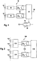
- an accumulator or battery pack 10 comprises a plurality of individual voltage-supplying cells 12 (rechargeable or non-rechargeable, such as accumulator cells or battery cells), which are each connected to a monitoring circuit 14.
- the monitoring circuit 14 monitors operating parameters of the cell 12 assigned to it, such as the cell voltage (overvoltage or undervoltage), the temperature, the Internal pressure, internal resistance or humidity of the cell (in order to be able to detect the leakage of electrolyte) and provides corresponding cell information.
- Such monitoring circuits 14 are already known in principle and are also used in conventional battery packs for monitoring individual battery cells.
- a signal evaluation circuit 18 is provided, which is electrically isolated (potential-free) with each monitoring circuit 14 via an optocoupler 16.
- the signal evaluation circuit 18 can either be provided as part of the accumulator or battery pack 10, or can be present as a separate component that can be connected to the accumulator or battery pack 10 and z. B. in a charger with which the accumulator or battery pack 10 can be charged, or a consumer that can be operated by the accumulator or battery pack 10, can be integrated.
- the optocoupler 16 is a coupling arrangement 16 which is implemented in a single component.
- a coupling arrangement can also be provided which comprises only a first coupling element, such as a light-emitting diode which communicates with a second coupling element, such as a photocell, provided outside the accumulator or battery pack.
- the second coupling element can be connected to the signal evaluation circuit provided externally to the accumulator or battery pack 10.
- the coupling arrangement can comprise an inductive or capacitive coupling.
- the coupling arrangement comprises a radio link (e.g. a local radio network within the battery pack).
- a radio link e.g. a local radio network within the battery pack.
- the signal evaluation circuit 18 does not generate high voltages, so that in principle an unlimited number of cells 12 are provided can. Furthermore, it is easily possible to expand a rechargeable battery pack 10 according to the invention by further individual cells 12 and monitoring circuits 14 without having to carry out complex measures on the signal evaluation circuit 18 for this purpose.
- the exchange of individual cells 12 is also possible without any problems, so that, for example, more cost-effective cells 12 with higher tolerances than previously usual can be used.
- the signal evaluation circuit 18 can then provide a signal directly via a connection 20 of the accumulator or battery pack 10 for a charger or for a consumer, which signal indicates the state of charge and / or malfunctions of individual accumulator cells.
- a voltage level or a bus communication signal for example, can be used as the signal.
- a temperature sensor 22 such as a temperature resistor, in particular an NTC resistor 22, already provided for signaling an increased temperature in the accumulator or battery pack 10, can be used to record an electrical variable, such as an electrical resistance or a temperature voltage or a signal from the signal evaluation circuit 18 to terminate the charging or discharging process are output to the charger and / or the consumer.
- an electrical variable such as an electrical resistance or a temperature voltage or a signal from the signal evaluation circuit 18 to terminate the charging or discharging process are output to the charger and / or the consumer.
- a further resistor 24 is connected in parallel with the NTC resistor 22 and can be switched on by the signal evaluation circuit 18.
- the overall resistance of the arrangement is reduced and thus the signal evaluation circuit 18 can signal to the charger or the consumer through the corresponding change in resistance that the temperature is too high, although this is not present, and thus, for example, termination of the charging or discharging process on the part of the connected Effect charger or the consumer.
- thermosensor which is evaluated by the charger or the consumer, or to short-circuit such a temperature sensor or some other element provided in the accumulator or battery pack (for example a coding resistor) or interrupt to effect a termination of the charging or discharging process.
- a temperature sensor which is evaluated by the charger or the consumer, or to short-circuit such a temperature sensor or some other element provided in the accumulator or battery pack (for example a coding resistor) or interrupt to effect a termination of the charging or discharging process.
- the signal transmission from the signal evaluation circuit 18 to the charger or consumer can also take place via an optical interface, a radio link or an inductive or capacitive coupling, or the Signal evaluation circuit 18 can control a circuit breaker built into accumulator or battery pack 10 in such a way that the flow of current into or out of accumulator pack 10 can be interrupted as a function of the signals from monitoring circuits 14.
- Fig. 2 shows a battery pack 100 according to a modified second embodiment. This differs from the battery pack 10 according to the first embodiment only with regard to the structure of the monitoring circuits 114, which, in contrast to the monitoring circuits 14 of the first embodiment, are designed in such a way that a monitoring circuit 114 monitors the operating parameters of several individual battery cells 112 and can provide corresponding cell information to the signal evaluation circuit 118 via optocouplers 116 not according to the invention.
- This cascaded structure makes it even easier to monitor large numbers of individual battery cells 112 in a battery pack 100, since only prefabricated modules, each comprising several battery cells 112 and a monitoring circuit 114 assigned to them, with a signal evaluation circuit 118 and optocouplers 116 (or other coupling arrangements, as described in connection with the first embodiment) must be combined. In addition, monitoring circuits 114 and coupling arrangements 116 can be saved.
Landscapes
- Engineering & Computer Science (AREA)
- Manufacturing & Machinery (AREA)
- Chemical & Material Sciences (AREA)
- Chemical Kinetics & Catalysis (AREA)
- Electrochemistry (AREA)
- General Chemical & Material Sciences (AREA)
- Physics & Mathematics (AREA)
- General Physics & Mathematics (AREA)
- Charge And Discharge Circuits For Batteries Or The Like (AREA)
- Secondary Cells (AREA)
- Battery Mounting, Suspending (AREA)
- Primary Cells (AREA)
Claims (6)
- Bloc d'accumulateurs ou de batteries (10 ; 100), comprenant plusieurs cellules (12 ; 112) individuelles délivrant une tension reliées les unes aux autres, un circuit de surveillance (14 ; 114) étant associé à chaque cellule (12 ; 112) pour surveiller une fonction de la cellule (12 ; 112) et pour délivrer, en fonction de celle-ci, une information de cellule, et chaque circuit de surveillance (14 ; 114) étant connecté à un arrangement de couplage (16 ; 116) qui, en fonction des informations de cellule, provoque la délivrance d'un signal d'état isolé galvaniquement de telle sorte que le circuit de surveillance (14 ; 114) est isolé galvaniquement par l'arrangement de couplage (16 ; 116) d'un circuit d'interprétation de signal (18 ; 118) qui délivre le signal d'état, caractérisé en ce que l'arrangement de couplage (16 ; 116) comprend un appareil pour établir une liaison radioélectrique.
- Bloc d'accumulateurs ou de batteries (10 ; 100) selon la revendication 1, caractérisé en ce que l'arrangement de couplage (16 ; 116) comprend un premier élément de couplage destiné à communiquer avec un deuxième élément de couplage disposé à l'extérieur du bloc d'accumulateurs ou de batteries (10 ; 100).
- Bloc d'accumulateurs ou de batteries (10 ; 100) selon la revendication 1, caractérisé en ce que le circuit d'interprétation de signal (18 ; 118) délivre au chargeur ou au consommateur un signal dépendant des informations de cellule par le biais d'une sonde de température (22) présente dans le bloc d'accumulateurs ou de batteries (10 ; 100), en ce que le circuit d'interprétation de signal (18 ; 118) influence une grandeur électrique de la sonde de température (22).
- Bloc d'accumulateurs ou de batteries (10 ; 100) selon la revendication 1, caractérisé en ce que le circuit d'interprétation de signal (18 ; 118) délivre au chargeur ou au consommateur un signal dépendant des informations de cellule par le biais d'une interface optique ou radioélectrique ou par le biais d'une unité de couplage inductive ou capacitive.
- Bloc d'accumulateurs ou de batteries (10 ; 100) selon la revendication 1, caractérisé en ce que le circuit d'interprétation de signal (18 ; 118) est configuré pour interrompre le flux de courant dans le bloc d'accumulateurs ou de batteries en fonction des informations de cellule par le biais d'un commutateur présent dans le bloc d'accumulateurs ou de batteries (10 ; 100).
- Bloc d'accumulateurs ou de batteries (100) selon l'une des revendications 1 à 5, caractérisé en ce que plusieurs cellules délivrant une tension sont respectivement associées (112) à l'un des circuits de surveillance (114).
Applications Claiming Priority (2)
| Application Number | Priority Date | Filing Date | Title |
|---|---|---|---|
| DE102007038532A DE102007038532A1 (de) | 2007-08-16 | 2007-08-16 | Akku- bzw. Batteriepack |
| PCT/EP2008/058315 WO2009021771A2 (fr) | 2007-08-16 | 2008-06-27 | Ensemble d'accumulateurs et/ou de batteries |
Publications (3)
| Publication Number | Publication Date |
|---|---|
| EP2181480A2 EP2181480A2 (fr) | 2010-05-05 |
| EP2181480B1 EP2181480B1 (fr) | 2015-10-07 |
| EP2181480B2 true EP2181480B2 (fr) | 2021-03-31 |
Family
ID=40229999
Family Applications (1)
| Application Number | Title | Priority Date | Filing Date |
|---|---|---|---|
| EP08774476.9A Active EP2181480B2 (fr) | 2007-08-16 | 2008-06-27 | Ensemble d'accumulateurs et/ou de batteries |
Country Status (5)
| Country | Link |
|---|---|
| EP (1) | EP2181480B2 (fr) |
| JP (1) | JP2010537362A (fr) |
| CN (1) | CN101779326A (fr) |
| DE (1) | DE102007038532A1 (fr) |
| WO (1) | WO2009021771A2 (fr) |
Families Citing this family (13)
| Publication number | Priority date | Publication date | Assignee | Title |
|---|---|---|---|---|
| DE102009036608A1 (de) * | 2009-08-07 | 2011-02-24 | Sanyo Component Europe Gmbh | Wiederaufladbare Batterie und Anschlussgerät zum Anschluss an eine wiederaufladbare Batterie |
| DE102009058783A1 (de) * | 2009-12-18 | 2011-06-22 | Continental Automotive GmbH, 30165 | Energiespeicheranordnung |
| DE102010007076A1 (de) | 2010-02-06 | 2011-08-11 | Fraunhofer-Gesellschaft zur Förderung der angewandten Forschung e.V., 80686 | Elektrischer Energiespeicher |
| DE102010040031B4 (de) * | 2010-08-31 | 2019-01-03 | Continental Automotive Gmbh | Überwachung der Spannung einer Zelle eines Batterie-Energiespeichers auf ein Über- und/oder Unterschreiten einer Referenzspannung |
| DE102011001107B3 (de) * | 2011-03-04 | 2012-01-26 | Ulrich Alber Gmbh | Schaltungsanordnung, elektrischer Energiespeicher und elektrisch betreibbares Gerät |
| DE102012019085B4 (de) | 2012-09-27 | 2026-06-03 | Volkswagen Aktiengesellschaft | Verfahren und Vorrichtung zum Überwachen von Betriebsgrößen einer Batterieanordnung mit mehreren Batteriezellen |
| DE102013219360A1 (de) * | 2013-09-26 | 2015-03-26 | Siemens Aktiengesellschaft | Energiespeichereinrichtung |
| JP2015220812A (ja) | 2014-05-15 | 2015-12-07 | 株式会社ケーヒン | 電圧検出装置 |
| DE102016008978A1 (de) | 2016-07-23 | 2018-01-25 | Man Truck & Bus Ag | Traktionsenergiespeichersystem für ein Fahrzeug |
| DE102016012228A1 (de) | 2016-10-13 | 2018-04-19 | Man Truck & Bus Ag | Traktionsenergiespeichersystem für ein Fahrzeug |
| DE102016013702A1 (de) | 2016-11-17 | 2018-05-17 | Man Truck & Bus Ag | Traktionsenergiespeichersystem mit Betriebsgrenzenbestimmung |
| DE102016014932A1 (de) | 2016-12-15 | 2018-06-21 | Man Truck & Bus Ag | Technik zum veränderlichen Verschalten eines Traktionsenergiespeichersystems |
| US11404886B2 (en) * | 2020-04-17 | 2022-08-02 | Snap-On Incorporated | Communicating battery charger |
Citations (4)
| Publication number | Priority date | Publication date | Assignee | Title |
|---|---|---|---|---|
| US5712568A (en) † | 1995-09-05 | 1998-01-27 | Ford Motor Company | Battery voltage measurement system |
| US5808469A (en) † | 1995-01-06 | 1998-09-15 | Chrysler Corporation | Battery monitor for electric vehicles |
| DE19822571A1 (de) † | 1998-05-20 | 1999-11-25 | Hubert Gauseweg | Anordnung zum Überwachen der Betriebsdaten von elektrischen Batterien |
| US20040199343A1 (en) † | 2003-04-01 | 2004-10-07 | Cardinal Mark E. | Integrated, self-powered battery monitoring device and system |
Family Cites Families (3)
| Publication number | Priority date | Publication date | Assignee | Title |
|---|---|---|---|---|
| AU738680B2 (en) * | 1997-01-21 | 2001-09-27 | Metrixx Limited | Signalling system |
| US6104967A (en) * | 1997-07-25 | 2000-08-15 | 3M Innovative Properties Company | Fault-tolerant battery system employing intra-battery network architecture |
| US6411912B1 (en) * | 1999-07-09 | 2002-06-25 | Alcatel | Voltage level bus translator and safety interlock system for battery modules |
-
2007
- 2007-08-16 DE DE102007038532A patent/DE102007038532A1/de not_active Withdrawn
-
2008
- 2008-06-27 WO PCT/EP2008/058315 patent/WO2009021771A2/fr not_active Ceased
- 2008-06-27 EP EP08774476.9A patent/EP2181480B2/fr active Active
- 2008-06-27 JP JP2010520511A patent/JP2010537362A/ja not_active Withdrawn
- 2008-06-27 CN CN200880103322A patent/CN101779326A/zh active Pending
Patent Citations (4)
| Publication number | Priority date | Publication date | Assignee | Title |
|---|---|---|---|---|
| US5808469A (en) † | 1995-01-06 | 1998-09-15 | Chrysler Corporation | Battery monitor for electric vehicles |
| US5712568A (en) † | 1995-09-05 | 1998-01-27 | Ford Motor Company | Battery voltage measurement system |
| DE19822571A1 (de) † | 1998-05-20 | 1999-11-25 | Hubert Gauseweg | Anordnung zum Überwachen der Betriebsdaten von elektrischen Batterien |
| US20040199343A1 (en) † | 2003-04-01 | 2004-10-07 | Cardinal Mark E. | Integrated, self-powered battery monitoring device and system |
Non-Patent Citations (3)
| Title |
|---|
| "Kopplung (Elektronik)", Wikipedia, 1 June 2006, Seite 1 † |
| "Kopplung (Elektronik)", Wikipedia, 11 April 2015, Seiten 1-2 † |
| "Kopplung (Elektronik)", Wikipedia, 28 September 2007, Seite 1 † |
Also Published As
| Publication number | Publication date |
|---|---|
| CN101779326A (zh) | 2010-07-14 |
| WO2009021771A3 (fr) | 2009-11-12 |
| EP2181480B1 (fr) | 2015-10-07 |
| WO2009021771A2 (fr) | 2009-02-19 |
| EP2181480A2 (fr) | 2010-05-05 |
| DE102007038532A1 (de) | 2009-02-19 |
| JP2010537362A (ja) | 2010-12-02 |
Similar Documents
| Publication | Publication Date | Title |
|---|---|---|
| EP2181480B1 (fr) | Ensemble d'accumulateurs et/ou de batteries | |
| EP0582913B1 (fr) | Dispositif de commutation | |
| EP2759018B1 (fr) | Système de gestion de batterie, batterie, véhicule automobile avec système de gestion de batterie et procédé de surveillance d'une batterie | |
| EP2368304B1 (fr) | Dispositif de stockage d'énergie et procédé pour faire fonctionner un tel dispositif | |
| DE102017104958B4 (de) | Batteriespeichersystem | |
| DE102011079126B4 (de) | Batteriemanagementsystem, Batterie, Kraftfahrzeug mit Batteriemanagementsystem sowie Verfahren zur Überwachung einer Batterie | |
| DE102012214091A1 (de) | Batterie-Management-System mit Datenschnittstelle für Batteriemodul, Batteriemodul mit Datenspeicher, Batteriesystem mit Batterie-Management-System sowie Batteriemodul und Kraftfahrzeug mit Batteriesystem | |
| DE102014202626A1 (de) | Batteriemanagementsystem für eine Batterie mit mehreren Batteriezellen und Verfahren | |
| DE102011079292A1 (de) | Batteriemanagementsystem und dazugehöriges Verfahren zur Bestimmung eines Ladezustands einer Batterie, Batterie mit Batteriemanagementsystem und Kraftfahrzeug mit Batteriemanagementsystem | |
| AT519841B1 (de) | Sicherheitsüberwachungseinheit | |
| DE102012210616A1 (de) | Batteriemanagementsystem mit erhöhter Robustheit gegenüber negativen Spannungen | |
| DE102014202394A1 (de) | Verfahren zur Erkennung einer Änderung eines elektrischen Kontakt-Übergangswiderstandes bei einem Batteriesystem sowie zur Ausführung eines solchen Verfahrens ausgebildetes Batteriesystem | |
| DE102012205553A1 (de) | Batteriezelle für ein Fahrzeug mit einer Vorrichtung zur Abkopplung und/oder Überbrückung von Anschlüssen der Batteriezelle | |
| WO2013120637A1 (fr) | Procédé de surveillance d'une batterie | |
| WO2021073965A1 (fr) | Circuit d'unité de commande pour véhicule automobile, véhicule automobile et procédé de fonctionnement du circuit d'unité de commande | |
| DE102012209174A1 (de) | Batterie und Kraftfahrzeug mit der Batterie | |
| DE102017218734A1 (de) | Hochspannungs-Betriebssystem und Verfahren zum Betreiben eines Hochspannung-Batteriesystems | |
| EP3573864A1 (fr) | Bloc de batterie et procédé permettant de faire fonctionner un bloc de batterie | |
| DE102012209177B4 (de) | Batteriesystem mit separat angeschlossener Bestimmungsschaltung sowie Batterie und Kraftfahrzeug mit Batteriesystem | |
| DE102013204509A1 (de) | Batteriemodul und Verfahren zum Überwachen eines Batteriemoduls | |
| EP2669242A1 (fr) | Chariot de manutention avec emplacements d'insertion de batterie | |
| EP2803109B1 (fr) | Système de batterie pour véhicule à moteur | |
| DE112018002328T5 (de) | Batteriesystem-überwachungsgerät und batteriepack | |
| DE102010011277B4 (de) | Batteriesystem und Verfahren zum Ändern des Ladungszustands eines Batteriesystems | |
| DE102010003216A1 (de) | Erhöhung der Performance und Zuverlässigkeit von Akkumulatorsystemen |
Legal Events
| Date | Code | Title | Description |
|---|---|---|---|
| PUAI | Public reference made under article 153(3) epc to a published international application that has entered the european phase |
Free format text: ORIGINAL CODE: 0009012 |
|
| AK | Designated contracting states |
Kind code of ref document: A2 Designated state(s): AT BE BG CH CY CZ DE DK EE ES FI FR GB GR HR HU IE IS IT LI LT LU LV MC MT NL NO PL PT RO SE SI SK TR |
|
| AX | Request for extension of the european patent |
Extension state: AL BA MK RS |
|
| 17P | Request for examination filed |
Effective date: 20100512 |
|
| RBV | Designated contracting states (corrected) |
Designated state(s): AT BE BG CH CY CZ DE DK EE ES FI FR GB GR HR HU IE IS IT LI LT LU LV MC MT NL NO PL PT RO SE SI SK TR |
|
| DAX | Request for extension of the european patent (deleted) | ||
| 17Q | First examination report despatched |
Effective date: 20110530 |
|
| GRAP | Despatch of communication of intention to grant a patent |
Free format text: ORIGINAL CODE: EPIDOSNIGR1 |
|
| INTG | Intention to grant announced |
Effective date: 20150708 |
|
| GRAS | Grant fee paid |
Free format text: ORIGINAL CODE: EPIDOSNIGR3 |
|
| GRAA | (expected) grant |
Free format text: ORIGINAL CODE: 0009210 |
|
| AK | Designated contracting states |
Kind code of ref document: B1 Designated state(s): AT BE BG CH CY CZ DE DK EE ES FI FR GB GR HR HU IE IS IT LI LT LU LV MC MT NL NO PL PT RO SE SI SK TR |
|
| REG | Reference to a national code |
Ref country code: GB Ref legal event code: FG4D Free format text: NOT ENGLISH |
|
| REG | Reference to a national code |
Ref country code: AT Ref legal event code: REF Ref document number: 754230 Country of ref document: AT Kind code of ref document: T Effective date: 20151015 Ref country code: CH Ref legal event code: EP |
|
| REG | Reference to a national code |
Ref country code: IE Ref legal event code: FG4D Free format text: LANGUAGE OF EP DOCUMENT: GERMAN |
|
| REG | Reference to a national code |
Ref country code: DE Ref legal event code: R096 Ref document number: 502008013460 Country of ref document: DE |
|
| REG | Reference to a national code |
Ref country code: NL Ref legal event code: MP Effective date: 20151007 |
|
| REG | Reference to a national code |
Ref country code: LT Ref legal event code: MG4D |
|
| PG25 | Lapsed in a contracting state [announced via postgrant information from national office to epo] |
Ref country code: LT Free format text: LAPSE BECAUSE OF FAILURE TO SUBMIT A TRANSLATION OF THE DESCRIPTION OR TO PAY THE FEE WITHIN THE PRESCRIBED TIME-LIMIT Effective date: 20151007 Ref country code: IS Free format text: LAPSE BECAUSE OF FAILURE TO SUBMIT A TRANSLATION OF THE DESCRIPTION OR TO PAY THE FEE WITHIN THE PRESCRIBED TIME-LIMIT Effective date: 20160207 Ref country code: IT Free format text: LAPSE BECAUSE OF FAILURE TO SUBMIT A TRANSLATION OF THE DESCRIPTION OR TO PAY THE FEE WITHIN THE PRESCRIBED TIME-LIMIT Effective date: 20151007 Ref country code: HR Free format text: LAPSE BECAUSE OF FAILURE TO SUBMIT A TRANSLATION OF THE DESCRIPTION OR TO PAY THE FEE WITHIN THE PRESCRIBED TIME-LIMIT Effective date: 20151007 Ref country code: NL Free format text: LAPSE BECAUSE OF FAILURE TO SUBMIT A TRANSLATION OF THE DESCRIPTION OR TO PAY THE FEE WITHIN THE PRESCRIBED TIME-LIMIT Effective date: 20151007 Ref country code: NO Free format text: LAPSE BECAUSE OF FAILURE TO SUBMIT A TRANSLATION OF THE DESCRIPTION OR TO PAY THE FEE WITHIN THE PRESCRIBED TIME-LIMIT Effective date: 20160107 Ref country code: ES Free format text: LAPSE BECAUSE OF FAILURE TO SUBMIT A TRANSLATION OF THE DESCRIPTION OR TO PAY THE FEE WITHIN THE PRESCRIBED TIME-LIMIT Effective date: 20151007 |
|
| PG25 | Lapsed in a contracting state [announced via postgrant information from national office to epo] |
Ref country code: PL Free format text: LAPSE BECAUSE OF FAILURE TO SUBMIT A TRANSLATION OF THE DESCRIPTION OR TO PAY THE FEE WITHIN THE PRESCRIBED TIME-LIMIT Effective date: 20151007 Ref country code: FI Free format text: LAPSE BECAUSE OF FAILURE TO SUBMIT A TRANSLATION OF THE DESCRIPTION OR TO PAY THE FEE WITHIN THE PRESCRIBED TIME-LIMIT Effective date: 20151007 Ref country code: PT Free format text: LAPSE BECAUSE OF FAILURE TO SUBMIT A TRANSLATION OF THE DESCRIPTION OR TO PAY THE FEE WITHIN THE PRESCRIBED TIME-LIMIT Effective date: 20160208 Ref country code: GR Free format text: LAPSE BECAUSE OF FAILURE TO SUBMIT A TRANSLATION OF THE DESCRIPTION OR TO PAY THE FEE WITHIN THE PRESCRIBED TIME-LIMIT Effective date: 20160108 Ref country code: LV Free format text: LAPSE BECAUSE OF FAILURE TO SUBMIT A TRANSLATION OF THE DESCRIPTION OR TO PAY THE FEE WITHIN THE PRESCRIBED TIME-LIMIT Effective date: 20151007 Ref country code: SE Free format text: LAPSE BECAUSE OF FAILURE TO SUBMIT A TRANSLATION OF THE DESCRIPTION OR TO PAY THE FEE WITHIN THE PRESCRIBED TIME-LIMIT Effective date: 20151007 |
|
| REG | Reference to a national code |
Ref country code: FR Ref legal event code: PLFP Year of fee payment: 9 |
|
| REG | Reference to a national code |
Ref country code: DE Ref legal event code: R026 Ref document number: 502008013460 Country of ref document: DE |
|
| PLBI | Opposition filed |
Free format text: ORIGINAL CODE: 0009260 |
|
| PG25 | Lapsed in a contracting state [announced via postgrant information from national office to epo] |
Ref country code: CZ Free format text: LAPSE BECAUSE OF FAILURE TO SUBMIT A TRANSLATION OF THE DESCRIPTION OR TO PAY THE FEE WITHIN THE PRESCRIBED TIME-LIMIT Effective date: 20151007 |
|
| 26 | Opposition filed |
Opponent name: PREH GMBH Effective date: 20160706 |
|
| PLAX | Notice of opposition and request to file observation + time limit sent |
Free format text: ORIGINAL CODE: EPIDOSNOBS2 |
|
| PG25 | Lapsed in a contracting state [announced via postgrant information from national office to epo] |
Ref country code: RO Free format text: LAPSE BECAUSE OF FAILURE TO SUBMIT A TRANSLATION OF THE DESCRIPTION OR TO PAY THE FEE WITHIN THE PRESCRIBED TIME-LIMIT Effective date: 20151007 Ref country code: DK Free format text: LAPSE BECAUSE OF FAILURE TO SUBMIT A TRANSLATION OF THE DESCRIPTION OR TO PAY THE FEE WITHIN THE PRESCRIBED TIME-LIMIT Effective date: 20151007 Ref country code: EE Free format text: LAPSE BECAUSE OF FAILURE TO SUBMIT A TRANSLATION OF THE DESCRIPTION OR TO PAY THE FEE WITHIN THE PRESCRIBED TIME-LIMIT Effective date: 20151007 Ref country code: SK Free format text: LAPSE BECAUSE OF FAILURE TO SUBMIT A TRANSLATION OF THE DESCRIPTION OR TO PAY THE FEE WITHIN THE PRESCRIBED TIME-LIMIT Effective date: 20151007 |
|
| PLAB | Opposition data, opponent's data or that of the opponent's representative modified |
Free format text: ORIGINAL CODE: 0009299OPPO |
|
| R26 | Opposition filed (corrected) |
Opponent name: PREH GMBH Effective date: 20160706 |
|
| PG25 | Lapsed in a contracting state [announced via postgrant information from national office to epo] |
Ref country code: SI Free format text: LAPSE BECAUSE OF FAILURE TO SUBMIT A TRANSLATION OF THE DESCRIPTION OR TO PAY THE FEE WITHIN THE PRESCRIBED TIME-LIMIT Effective date: 20151007 |
|
| PLBB | Reply of patent proprietor to notice(s) of opposition received |
Free format text: ORIGINAL CODE: EPIDOSNOBS3 |
|
| PG25 | Lapsed in a contracting state [announced via postgrant information from national office to epo] |
Ref country code: BE Free format text: LAPSE BECAUSE OF NON-PAYMENT OF DUE FEES Effective date: 20160630 |
|
| PG25 | Lapsed in a contracting state [announced via postgrant information from national office to epo] |
Ref country code: MC Free format text: LAPSE BECAUSE OF FAILURE TO SUBMIT A TRANSLATION OF THE DESCRIPTION OR TO PAY THE FEE WITHIN THE PRESCRIBED TIME-LIMIT Effective date: 20151007 |
|
| REG | Reference to a national code |
Ref country code: CH Ref legal event code: PL |
|
| REG | Reference to a national code |
Ref country code: IE Ref legal event code: MM4A |
|
| PG25 | Lapsed in a contracting state [announced via postgrant information from national office to epo] |
Ref country code: CH Free format text: LAPSE BECAUSE OF NON-PAYMENT OF DUE FEES Effective date: 20160630 Ref country code: LI Free format text: LAPSE BECAUSE OF NON-PAYMENT OF DUE FEES Effective date: 20160630 |
|
| PG25 | Lapsed in a contracting state [announced via postgrant information from national office to epo] |
Ref country code: IE Free format text: LAPSE BECAUSE OF NON-PAYMENT OF DUE FEES Effective date: 20160627 |
|
| REG | Reference to a national code |
Ref country code: FR Ref legal event code: PLFP Year of fee payment: 10 |
|
| REG | Reference to a national code |
Ref country code: AT Ref legal event code: MM01 Ref document number: 754230 Country of ref document: AT Kind code of ref document: T Effective date: 20160627 |
|
| PG25 | Lapsed in a contracting state [announced via postgrant information from national office to epo] |
Ref country code: AT Free format text: LAPSE BECAUSE OF NON-PAYMENT OF DUE FEES Effective date: 20160627 |
|
| RIC2 | Information provided on ipc code assigned after grant |
Ipc: H01M 10/48 20060101AFI20171207BHEP Ipc: G01R 31/36 20060101ALI20171207BHEP |
|
| PG25 | Lapsed in a contracting state [announced via postgrant information from national office to epo] |
Ref country code: CY Free format text: LAPSE BECAUSE OF FAILURE TO SUBMIT A TRANSLATION OF THE DESCRIPTION OR TO PAY THE FEE WITHIN THE PRESCRIBED TIME-LIMIT Effective date: 20151007 Ref country code: HU Free format text: LAPSE BECAUSE OF FAILURE TO SUBMIT A TRANSLATION OF THE DESCRIPTION OR TO PAY THE FEE WITHIN THE PRESCRIBED TIME-LIMIT; INVALID AB INITIO Effective date: 20080627 |
|
| REG | Reference to a national code |
Ref country code: FR Ref legal event code: PLFP Year of fee payment: 11 |
|
| PG25 | Lapsed in a contracting state [announced via postgrant information from national office to epo] |
Ref country code: TR Free format text: LAPSE BECAUSE OF FAILURE TO SUBMIT A TRANSLATION OF THE DESCRIPTION OR TO PAY THE FEE WITHIN THE PRESCRIBED TIME-LIMIT Effective date: 20151007 Ref country code: MT Free format text: LAPSE BECAUSE OF FAILURE TO SUBMIT A TRANSLATION OF THE DESCRIPTION OR TO PAY THE FEE WITHIN THE PRESCRIBED TIME-LIMIT Effective date: 20151007 Ref country code: LU Free format text: LAPSE BECAUSE OF NON-PAYMENT OF DUE FEES Effective date: 20160627 |
|
| PG25 | Lapsed in a contracting state [announced via postgrant information from national office to epo] |
Ref country code: BG Free format text: LAPSE BECAUSE OF FAILURE TO SUBMIT A TRANSLATION OF THE DESCRIPTION OR TO PAY THE FEE WITHIN THE PRESCRIBED TIME-LIMIT Effective date: 20151007 |
|
| RAP2 | Party data changed (patent owner data changed or rights of a patent transferred) |
Owner name: ROBERT BOSCH GMBH |
|
| PUAH | Patent maintained in amended form |
Free format text: ORIGINAL CODE: 0009272 |
|
| STAA | Information on the status of an ep patent application or granted ep patent |
Free format text: STATUS: PATENT MAINTAINED AS AMENDED |
|
| 27A | Patent maintained in amended form |
Effective date: 20210331 |
|
| AK | Designated contracting states |
Kind code of ref document: B2 Designated state(s): AT BE BG CH CY CZ DE DK EE ES FI FR GB GR HR HU IE IS IT LI LT LU LV MC MT NL NO PL PT RO SE SI SK TR |
|
| REG | Reference to a national code |
Ref country code: DE Ref legal event code: R102 Ref document number: 502008013460 Country of ref document: DE |
|
| P01 | Opt-out of the competence of the unified patent court (upc) registered |
Effective date: 20230509 |
|
| PGFP | Annual fee paid to national office [announced via postgrant information from national office to epo] |
Ref country code: GB Payment date: 20250620 Year of fee payment: 18 |
|
| PGFP | Annual fee paid to national office [announced via postgrant information from national office to epo] |
Ref country code: FR Payment date: 20250626 Year of fee payment: 18 |
|
| PGFP | Annual fee paid to national office [announced via postgrant information from national office to epo] |
Ref country code: DE Payment date: 20250814 Year of fee payment: 18 |