EP2181638B1 - Panier de lave-vaisselle pliable - Google Patents
Panier de lave-vaisselle pliable Download PDFInfo
- Publication number
- EP2181638B1 EP2181638B1 EP08019207A EP08019207A EP2181638B1 EP 2181638 B1 EP2181638 B1 EP 2181638B1 EP 08019207 A EP08019207 A EP 08019207A EP 08019207 A EP08019207 A EP 08019207A EP 2181638 B1 EP2181638 B1 EP 2181638B1
- Authority
- EP
- European Patent Office
- Prior art keywords
- wire
- mesh
- base
- foldable
- edge
- Prior art date
- Legal status (The legal status is an assumption and is not a legal conclusion. Google has not performed a legal analysis and makes no representation as to the accuracy of the status listed.)
- Not-in-force
Links
- 238000005452 bending Methods 0.000 description 11
- 238000004519 manufacturing process Methods 0.000 description 3
- 239000000463 material Substances 0.000 description 2
- 239000002184 metal Substances 0.000 description 2
- 239000004033 plastic Substances 0.000 description 2
- 229920003023 plastic Polymers 0.000 description 2
- 229910000831 Steel Inorganic materials 0.000 description 1
- 230000001419 dependent effect Effects 0.000 description 1
- 230000000694 effects Effects 0.000 description 1
- 239000003623 enhancer Substances 0.000 description 1
- 239000011521 glass Substances 0.000 description 1
- 239000006223 plastic coating Substances 0.000 description 1
- 239000010959 steel Substances 0.000 description 1
- 239000000126 substance Substances 0.000 description 1
- XLYOFNOQVPJJNP-UHFFFAOYSA-N water Substances O XLYOFNOQVPJJNP-UHFFFAOYSA-N 0.000 description 1
Images




Classifications
-
- A—HUMAN NECESSITIES
- A47—FURNITURE; DOMESTIC ARTICLES OR APPLIANCES; COFFEE MILLS; SPICE MILLS; SUCTION CLEANERS IN GENERAL
- A47L—DOMESTIC WASHING OR CLEANING; SUCTION CLEANERS IN GENERAL
- A47L15/00—Washing or rinsing machines for crockery or tableware
- A47L15/42—Details
- A47L15/50—Racks ; Baskets
- A47L15/503—Racks ; Baskets with foldable parts
Definitions
- the invention relates to a foldable dishwasher basket.
- baskets especially dishwasher baskets
- dishwasher baskets are made of a wire mesh, which is entirely manufactured and assembled by the basket suppliers.
- the appearance of such baskets is comparable to an open box, which means that they take up very much room and thus are quite expensive for transportation.
- Some other baskets are designed to be stackable, but in case of dishwasher baskets it is, in the most cases, impossible due to the various number of prongs and racks integrated inside the baskets.
- DE 201 02 169 U1 discloses a basket, which is designated to hold the items to be washed in a dish washer for home use, especially with plates and glasses, and which comprises a bottom side and edges which consist of a large number of bars.
- IT 53045 discloses a dishwasher basket comprising a base mesh embossed in plastic and reinforced by steel bars, lateral wings of the same mesh type and hinged to the four sides of the base mesh.
- DE 10 2004 060 951 A1 discloses a dishwasher basket for a dishwasher with a base frame, consisting of a base plane, with an edge protruding upwards at at least one side, where the edge protruding upwards extends at least the height of the spikes of the dishwasher basket showing upwards and, eventually, the height of the dish parts arranged in at least one dish basket towards the top.
- US 6,349,877 B1 discloses a tote box which is assembled from a box blank, corner enhancers and a self-locking top rail, wherein when folded into the appropriate shape, the box results in a bottom, two opposed end walls, and two opposed side walls and said top rail which is channel shaped extends around the top edge of the tote box to hold the erected box blank in an assembled relationship and to reinforce the top edge of the tote box.
- foldable dishwasher basket here after referred to as foldable basket according to claim 1.
- Advantageous embodiments are described especially in the dependent claims.
- the foldable dishwasher basket comprises
- the foldable basket according to the invention allows to provide a basket design that allows flexibility and reduces transportation costs.
- the foldable basket according to the invention needs less space during storage and transportation, which saves costs, as storage and transportation costs depend on the required space.
- the foldable basket according to the invention can be unfolded at an largely arbitrary time, for example when mounting the basket into a dishwasher, so that it also has a high degree of flexibility.
- the fixing element is or comprises at least one fixation wire, wherein at least one side mesh comprises at least one side wire extending, preferably perpendicularly, towards and/or beyond the upper edge of the side mesh, wherein preferably the at least one fixation wire is formed like an at least substantially rectangular loop and surrounds the side meshes along their upper edges and is clippable over at least one, especially upper, end of the at least one side wire.
- a fixation wire is at least relatively easy and cheap to produce and to handle, furthermore it at least substantially does not affect the functionality of the basket, for example as it at least normally needs only little space.
- the foldable basket especially at least one side mesh and/or the base mesh, comprises at least one wire, where the at least one wire is made out of metal, plastics or metal with a plastic coating or another material or combination of different materials.
- the wire has a round, especially circular cross section.
- a frame that is fixable to the upper edge of at least one side mesh for fixation thereof in the upright position, wherein the frame comprises a groove for clipping fixation onto the upper edge of the at least one side mesh, wherein the frame preferably comprises at least one bottom lid which can be bent inwards to cover at least a substantial part of the groove and/or the gap formed by the groove.
- a groove for clipping fixation allows a stable and, at the same time, easy fixing and at least substantially does not effect the functionality of the basket.
- a bottom lid which can be bent inwards is able to cover at least parts of the groove and/or the gap formed by the groove and therefore to protect the remaining opening of the groove from dirt, water or other substances
- the side mesh comprises at least one interior side wire extending, preferably perpendicularly, towards and/or beyond the upper edge of the side mesh, wherein the at least one bottom lid comprises at least one cutout which leave(s) open space for the at least one interior side wire.
- This can improve the closing of the lid, so that a larger fraction of the gap or groove can be covered.
- the at least one side mesh is hold in its upright orientation by at least one snapping connection or clipping connection, wherein preferably at least one base wire or side wire is used as a snapping or clipping part.
- a snapping connection or clipping connection is an advantageous connection, as the parts, on the one hand are at least relatively easy to connect and, on the other hand, an at least relatively stable and/or durable connection is formed. Furthermore, it is normally at least relatively easy to separate the connection again.
- the base mesh comprises
- the side mesh comprises a lower side wire at its lower edge opposite to its upper edge, wherein the lower side wire is clippable over at least one base wire end to fix the side mesh in the upright orientation at the base mesh, wherein preferably a further base wire works as a fixation point for the side mesh in its upright position and/or wherein preferably the lower side wire is fixed to another side wire extending perpendicularly towards or beyond the upper side wire,
- a connection wherein the lower side wire is clippable over at least one base wire can be produced at least relatively cost-saving, as normally, a smaller number of additional parts is necessary, as the used wires usually are existing anyway so that they preferably only have to be arranged in a different way.
- the foldable basket comprises four side meshes, wherein at least two side meshes, especially on opposite sides of the base mesh, are bendably connected with the base mesh and/or wherein at least two side meshes, especially on the remaining opposite sides of the base mesh, are rotatably connected to the base mesh.
- a bendable connection can establish a very stable connection, as usually, the at least one connecting element is a part which is fixed in both meshes.
- the angle between the meshes can normally adjusted very precisely, which can allow a very accurate manufacturing.
- At least two side meshes are arranged or arrangeble at least substantially in the same plane as the base mesh, preferably for storing or transporting, or angular with respect to the base mesh. This can help to reduce the transportation costs further, as the height of the package for the basket can be at least relatively low.
- the rotatable connection between the base mesh and the at least one side mesh is realized by a first and a second group of hinges, wherein the first group of hinges comprises hinges which are open to the inside and the second group of hinges comprises hinges which are open to the outside of the base mesh.
- first group of hinges comprises hinges which are open to the inside
- second group of hinges comprises hinges which are open to the outside of the base mesh.
- At least one side mesh comprises at least one side wire extending, preferably perpendicularly, cowards and/or beyond the upper edge of the side mesh, wherein the side wire of the side mesh comprises at least one hinged end, wherein the hinged end is hingable or hinged between two base wires within an at least substantially parallel section, wherein preferably the two base wires have along their at least substantially parallel section such a distance that the hinged end fits in between them so that they form two stopping elements for the hinged end when arranged in the upright position, where the two base wires are preferably at least substantially directly adjacent to the hinged end on opposite sides.
- This embodiment also allows a manufacturing with at least relatively low costs, as, for the connection, no or at least not many additional parts are necessary.
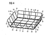
- FIG 4 shows basic elements of a basket, especially of a dishwasher basket.
- the basket comprises a base mesh 2 and four side meshes 3 to 6.
- the base mesh 2 comprises at its first edge or edge area a first base wire 21. At its second edge, which is perpendicular to the first base wire 21, a third base wire 23 is arranged. At its third edge, which is perpendicular to the second base wire 23 and opposed to the first base wire 21, a forth base wire 24 is arranged. At its forth edge, which is perpendicular to the forth base wire 24 and opposed to the third base wire 23, a fifth base wire 25 is arranged. In addition, a second base wire 22 is arranged between and parallel to the third base wire 23 and the fifth base wire 25.
- the first side mesh 3 comprises at its first edge or edge area a first side wire 31.
- the first side wire 31 is the lower side wire and forms the lower edge of the side mesh, at least when the side mesh is in an upright orientation.
- a second side wire 32 is arranged.
- a third side wire 33 is arranged.
- the third side wire 33 is the upper side wire and forms the upper edge of the side mesh, at least when the side mesh is.in an upright orientation.
- a forth side wire 34 is arranged at its forth edge, which is perpendicular to the third side wire 33 and opposed to the second side wire 32.
- the second side mesh 4 comprises at its first edge or edge area a first side wire 41.
- a second side wire 42 is arranged.
- a third side wire 43 is arranged.
- a forth side wire 44 is arranged.
- the third side mesh 5 comprises at its first edge or edge area a first side wire 51.
- a second side wire 52 is arranged.
- a third side wire 53 is arranged.
- a forth side wire 54 is arranged.
- the forth side mesh 6 comprises at its first edge or edge area a first side wire 61. At its second edge, which is perpendicular to the first side wire 61, a second side wire 62 is arranged. At its third edge, which is perpendicular to the second side wire 62 and opposed to the first side wire 61, a third side wire 63 is arranged. At its forth edge, which is perpendicular to the third side wire 63 and opposed to the second side wire 62, a forth side wire 64 is arranged.
- the four side meshes 3 to 6 are in their upright positions, whereas the base mesh 2 is in a horizontal position.
- the first side wire 31 of the first side mesh 3, which is horizontal and the lowest side wire in the upright, assembled position of the first side mesh 3 is arranged near or next to the third base wire 23.
- the first side wire 41 of the second side mesh 4 which is horizontal and the lowest side wire in the upright, assembled position of the second side mesh 4 is arranged near or next to the forth base wire 24.
- the first side wire 51 of the third side mesh 5, which is horizontal and the lowest side wire in the upright, assembled position of the third side mesh 5 is arranged near or next to the fifth base wire 25.
- the first side wire 61 of the forth side mesh 6, which is horizontal and the lowest side wire in the upright, assembled position of the forth side mesh 6 is arranged near or next to the first base wire 21.
- the third side wires 33, 43, 53 and 53 of the side meshes 3 to 6 are horizontal and the highest side wires of the respective side meshes.in their upright positions.
- the second side wires 32, 42, 52 and 52 as well as the forth side wires 34, 44; 54 and 54 of the side meshes 3 to 6 are vertical in their upright positions.
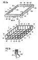
- FIG 1 and 2 show a detail of a foldable basket according to the invention, including parts of the side meshes 3, 4 and 5 and, not shown, 6, as well as a base mesh 2.
- the basket comprises a looped wire 72 with an at least substantially rectangular shape so that it can be clipped over the upper side wires 33, 43, 53 and 63 in their upright positions which form the upper rims the side meshes 3 to 6.
- the forth side wire 34 of the side mesh 3 comprises, at its outer end, an outward bending 346 for fixing the looped wire 72.
- the second side wire 52 of the side mesh 5 comprises, at its outer end, an outward bending 526.
- the remaining vertical side wires can comprise corresponding bendings, which is, however, not shown in the figures.
- the looped wire 72 can be clipped over the bending 346 of the forth side wire 34 of the side mesh 3 and over the bending 526 of the second side wire 52 of the base mesh 5 in their upright positions and, which is not shown in FIG 1 , preferably over corresponding bendings of the remaining horizontal side wires, which are arranged also in their upright positions.
- the looped wire 72 After clipping the looped wire 72 over the side wires, which is shown partly in FIG 2 , the looped wire 72 is arranged adjacent to the third side wires 33, 43, 53 and 63 of side meshes 3, 4, 5 and 6.
- the bendings 346 and 526 can preferably be made in a way that they return to their original position after clipping the looped wire 72 over them.
- FIG 3a and b show other embodiments of a foldable basket according to the invention, with a base mesh 2 and side meshes 3 to 6.
- the connection of the side meshes 3 to 6 is accomplished by an at least substantially rectangular frame 8 which comprises four sides 83 to 86 where each side 83 to 86 comprises a groove along its bottom side to incorporate the side wires 33, 43, 53 and 63, respectively.
- Each side mesh 3 to 6 comprises side wires 32, 42, 52, 62, 34, 44, 54 and 64, respectively, at its horizontal edges as well as side meshes 371 to 374, 471 to 474, 571 to 574 and 671 to 674, respectively, in between them.
- each side 83 to 86 comprises a bottom lid 836 to 876 at its outer bottom side where each bottom lid comprises four recesses 831 to 834, 841 to 844, 851 to 854.and 861 to 864, respectively.
- the recesses 831 to 834, 841 to 844, 851 to 854 and 861 to 864, respectively, have the same distance from the edges as the corresponding side meshes 371 to 374, 471 to 474, 571 to 574 and 671 to 674, respectively.
- the bottom lids 836 to 876 are bent inwards so that the recesses 831 to 834, 841 to 844, 851 to 854 and 861 to 864, respectively, are filled out by the side meshes side 371 to 374, 471 to 474, 571 to 574 and 671 to 674, respectively.
- FIG 3b shows a cross section through the part 83.
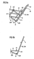
- FIG 5a to 7 show details of a foldable basket according to the invention.
- the figures show a part of a base mesh 2 and a part of a side mesh 3 which are in communication with each other.
- the base mesh 2 comprises a first base wire 21 which is perpendicular to a second base wire 22 and a third base wire 23.
- the base wires 22 and 23 are parallel to each other, whereas the third base wire 23 is, with respect to the not shown center of the base mesh 2, arranged outwards relative to the second base wire 22.
- the side mesh 3 comprises a first side wire 31, which is perpendicular to a second side wire 32.
- the second side wire 32 comprises two segments 323 and 324 between which a bending 325 with an angle of about 90° is arranged.
- the bending 325 surrounds the first side wire 31.
- the segment 323 has a hinged end 321 which encompasses the second base wire 22 when it is hooked over the second base wire 22.
- a forth side wire 34 which is parallel to the second side wire 32 can be seen in FIG 5a , where the forth side wire 34 is of the same form as the second side wire 32. Consequently, it also comprises a looped end 341 which also encompasses the second base wire 22 when it is hooked over the second base wire 22.
- the lower side wire 31 does not necessarily need to be directly adjacent to base wire 23.
- base wire 23 can be located closer to base wire 22 as well.
- Ease wire 22 works as a vertical fixation point for the side mesh 3, it guarantees and/or enables the horizontal position of side wire 323.
- base wire 23 is as distant as possible from base wire 22, so that the lever formed by side wire 32 is as long as possible.
- wire 31 does not necessarily need to be bent around wire 31.
- the position of wire 31 regarding wire 324 is at least substantially depending on the geometry of wire end 211. It needs to be in the right position to be able to be clipped over wire end 211.
- FIG 5a and FIG 5b show a part of the side mesh 3 in a position, where its hinged side wire ends 321 and 341 are not hinged over the second base wire 22 of the base mesh 2.
- FIG 6a and FIG 6b show a part of the side mesh 3 in a position; where its hinged side wire ends 341 and, not shown, 321, are hinged over the second base wire 22 of the base mesh 2.
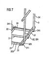
- FIG 7 shows parts of the side mesh 3 in an upright position with respect to the base mesh 2.
- the first side wire 31 is clipped over the end portion 211 of the first base wire 21 and the end portion 241 of the forth base wire 24.
- the first side wire 31 is arranged parallel and adjacent to the third base wire 23.
- the first side wire 31 In a tilted position, after clipping the first side wire 31 over the end portion 211 of the first base wire 21 and the end portion 241 of the forth base wire 24, the first side wire 31 could be arranged with distance to the third base wire 23.
- FIG 8a and 8b show a detail of another embodiment of a foldable basket according to the invention with a second side wire 32 of the side mesh 3 and a first base wire 21 of the base mesh. 2 from the side of the base mesh 2.
- two parallel base wires 22 and 23 are shown, which are perpendicular with respect to the first base wire 21.
- the base wires 22 and 23 have a distance which is slightly more than the diameter of.a side wire.
- the second side wire 32 comprises a hooked end 322 which is formed similar like a question mark with its lower part merging onto the second side wire 32.
- the outer part of the hooked end 322 its curved nearly like a half circle where the end area of the hooked end 322 is directed at least nearly perpendicular with respect to the second side wire 32.
- the hooked end 322 is intended, when a connection with base mesh 2 is to be formed, to be rotated around the third side wire 23 of base mesh 2.
- FIG 8a shows the second side wire 32 in parallel state with respect to the first base wire 21.
- the hooked end 322 can be hooked in between the second base wire 22 and the third base wire 23. Therefore, when the base wire 21 and the side wire 32 are pulled away from each other, the hooked end 322 will hold the two wires together. Substantially, in a translational movement, the side wire 32 can only be moved upwards with respect to the base mesh 2.
- FIG 8b shows the second side wire 32 in perpendicular, upright state with respect to the first base wire 21.
- the hook 322 is now clamped between the second base wire 22 and the third base wire 23 which means that the side wire 32 can be moved translationally in neither direction, only a rotational movement is possible.
- FIG 9 shows the arrangement according to FIG 8b from above the base mesh 2 where, as a further base wire, the forth base wire 24 can be seen which is parallel to the first base wire 21. Another base wire is arranged between the base wires 21 and 24.
- the forth side wire 34 can be seen. It comprises, at its lower end, a hook 342 which is formed like the hook 322.
- the hook 342 is surrounding the base mesh 23 in the same manner like the hook 322.
- FIG 10 shows a principle of another embodiment of the invention where the base mesh 2 is viewed from the side. It can be seen the first base mesh 21 and, perpendicular, the third base mesh 23. Furthermore, the perpendicular side wires 31 and 32 of side mesh 3 can be seen, where side wire 31 is parallel to base mesh 23.
- a hook 212 is arranged.
- the hook 212 starts perpendicular to the first base wire 21 and bends inwards towards the base wire 21, where its outest end is bent into the opposite direction away from the first base wire 21.
- the hook 212 grips around the side mesh 31 and therefore connects the base mesh 2 and the side mesh 3.
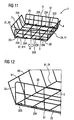
- FIG 11 shows a partly assembled basket 1 according to the invention with a base mesh 2 and two separate side meshes 3 and 5 on opposite sides.
- the two remaining opposite side meshes 4 and 6 are connected integrally and bendably or foldably with the base mesh 2.
- the opposite side meshes 3 and 5 are connected with the base mesh 2 by hooks 233 to 236 and well as 253 to 256, respectively.
- a first group 253, 254 of hinges are fixed to the fifth base wire 25 whose openings are oriented to the inside of the base mesh 2.
- the hinges are formed similar like the hinge 212 shown in FIG 10 .
- a second group 255 and 256 of hinges is arranged besides the first group of hinges whose openings are oriented to the outside of the base mesh 2.
- a first group 233, 234 of hinges is fixed to the third base wire 23 whose openings are oriented to the outside of the base mesh 2. Furthermore, a second group 235 and 236 of hinges is arranged beside the first group of hinges whose openings are oriented to the inside of the base mesh 2.
- the side mesh 3 is rotated with respect to base mesh 2.
- the side mesh 3 is positioned with upright orientation with the center of the first, lower side wire 31 over the center of base wire 23, where side wire 31 is rotated with respect to base wire 23 around a rotation axis M which is extending upwardly through the center of side mesh 3.
- the side mesh 5 and the base mesh 2 are connected in the same way.
- FIG 12 shows a part of the base mesh 2 according to FIG 11 with parts of the side meshes 3 and 6 and hinges 233 and 234.
- FIG 13a to 13d show another embodiment of a foldable basket 1 which is, in FIG 13d , stapled with two other baskets 1' and 1" .
- FIG 13a shows a base mesh 2 and four side meshes 3 to 6 wherein the four side meshes 3 to 6 are arranged in a transporting and/or storing orientation.
- the four side meshes 3 to 6 are in the same plane as the base mesh 2.
- FIG 13b shows the foldable basket 1 in an unassembled state, where base 2 and side meshes 3 to 6 are already connected and each side mesh 3 to 6 is tilted with respect to the base mesh 2 from the upright position with an angle of about 30°.
- FIG 13d shows three unassembled baskets 1, 1' and 1" in a stapled state.
- Each basket 1, 1', 1 " has its side meshes 3 to 6 tilted with respect to the base mesh 2 from the upright position with an angle of about 30° so that the.baskets can be stapled easily and space-savingly.
Landscapes
- Rigid Containers With Two Or More Constituent Elements (AREA)
- Food-Manufacturing Devices (AREA)
- Table Devices Or Equipment (AREA)
Claims (11)
- Panier pliable pour lave-vaisselle (1), comprenanta) un maillage de base (2), en particulier au moins substantiellement rectangulaire, etb) au moins deux, en particulier quatre, maillages latéraux pliables, flexibles ou articulés (3, 4, 5, 6),c) où chaque maillage latéral pliable, flexible ou articulé (3, 4, 5, 6) est relié ou reliable de manière pivotable, de préférence par au moins un élément de charnière, de manière pliable ou de manière flexible au maillage de base (2),d) où chaque maillage latéral (3) comprend, sur la base d'une orientation verticale du maillage latéral (3), un bord supérieur,e) où les maillages latéraux sont fixés dans leur orientation verticale par au moins un élément de fixation qui s'étire au moins substantiellement le long, de préférence autour, des bords supérieurs des maillages latéraux.
- Panier pliable selon la revendication 1,a) où l'élément de fixation est ou comprend au moins un fil de fixation (72),b) où au moins un maillage latéral (3 ; 5) comprend au moins un fil latéral (34 ; 52) s'étirant, de préférence perpendiculairement, vers et/ou au-delà du bord supérieur du maillage latéral (3 ; 5),c) où de préférence l'au moins un fil de fixation (72) est formé comme une boucle au moins substantiellement rectangulaire et entoure les maillages latéraux (3, 4, 5, 6) le long de leurs bords supérieurs et est clipsable sur au moins une extrémité (346 ; 526), surtout supérieure, de l'au moins un fil latéral (34 ; 52).
- Panier pliable selon l'une des revendications précédentes,a) avec un cadre (8) qui est fixable au bord supérieur (33, 43, 53, 63) d'au moins un maillage latéral (3, 4, 5, 6) pour la fixation de celui-ci dans la position verticale,b) où le cadre (8) comprend une rainure pour la fixation par clipsage sur le bord supérieur (33, 43, 53, 63) de l'au moins un maillage latéral (3, 4, 5, 6),c) où le cadre (8) comprend de préférence au moins un couvercle de fond (836, 846, 856 et 866) qui peut être plié vers l'intérieur pour couvrir au moins une partie substantielle de la rainure.
- Panier pliable selon l'une des revendications précédentes,a) où le maillage latéral (3) comprend au moins un fil latéral intérieur (371 à 374) s'étirant, de préférence perpendiculairement, vers et/ou au-delà du bord supérieur du maillage latéral (3),b) où l'au moins un couvercle de fond (836 à 876) comprend au moins une découpe (831 à 834) qui laisse un espace ouvert pour l'au moins un fil latéral intérieur (371 à 374).
- Panier pliable selon l'une des revendications précédentes,a) où l'au moins un maillage latéral (3, 4, 5, 6) est maintenu dans son orientation verticale par au moins une connexion par encliquetage ou connexion par clipsage,b) où de préférence au moins un fil de base ou fil latéral (31) est utilisé comme une partie d'encliquetage ou clipsage.
- Panier pliable selon l'une des revendications précédentes,a) où le maillage de base (2) comprenda1) un premier fil de base (21) à un premier bord du maillage de base (2) avec une première extrémité de fil de base (211),a2) un deuxième fil de base (22) qui est perpendiculaire au premier fil de base (21),a3) un troisième fil de base (23) à un deuxième bord en face du premier bord du maillage de base (2) qui est parallèle au deuxième fil de base (22),a4) où le troisième fil de base (23) est, par rapport au maillage de base (2), disposé vers l'extérieur par rapport au deuxième fil de base (22),b) où l'au moins un maillage latéral (3) comprendb1) un premier fil latéral inférieur (31) à un premier bord inférieur du maillage latéral (3),b2) un deuxième fil latéral (32) à un deuxième bord du maillage latéral (3),b3) un troisième fil latéral supérieur (33) à un troisième bord supérieur du maillage latéral, parallèle et en face du premier fil latéral (31) et perpendiculaire au deuxième fil latéral (32),b3) un quatrième fil latéral (34) à un quatrième bord du maillage latéral, perpendiculaire au premier fil latéral (31) et de préférence parallèle et en face du deuxième fil latéral (32),c) où de préférence le panier pliable comprend au moins un premier (3) et un deuxième (4) maillage latéral, où le premier maillage latéral (3) est, dans un état assemblé, au moins substantiellement perpendiculaire par rapport au deuxième maillage latéral (4) et par rapport au maillage de base (2) et/oud) où de préférence le premier fil latéral (31) du premier maillage latéral (3) est relié de manière pivotable ou pliable ou flexible au troisième fil de base (23) du maillage de base (2).
- Panier pliable selon l'une des revendications précédentes,a) où le maillage latéral comprend un fil latéral inférieur (31) à son bord inférieur en face de son bord supérieur,b) où le fil latéral inférieur (31) est clipsable sur au moins une extrémité de fil de base (211) pour fixer le maillage latéral dans l'orientation verticale au maillage de base (2),c) où de préférence un ultérieur fil de base (22) sert de point de fixation pour le maillage latéral (3) dans sa position verticale et/oud) où de préférence le fil latéral inférieur (31) est fixé à un autre fil latéral (32) s'étirant perpendiculairement vers ou au-delà du fil latéral supérieur (33),d1) où de préférence l'autre fil latéral (32) est plié avec un angle, surtout au moins substantiellement perpendiculaire et/oud2) où de préférence l'autre fil latéral (32) a une extrémité articulée (321) qui englobe un ou l'ultérieur fil de base (22) qui est de préférence parallèle à un autre fil de base (23).
- Panier pliable selon l'une des revendications précédentes,a) où le panier pliable (1) comprend quatre maillages latéraux (3, 4, 5, 6),b) où au moins deux maillages latéraux (4, 6), surtout sur les côtés opposés du maillage de base (2), sont reliés de manière flexible au maillage de base (2) et/ouc) où au moins deux maillages latéraux (3, 5), surtout sur les côtés opposés restants du maillage de base (2), sont reliés de manière pivotable maillage de base.
- Panier pliable selon l'une des revendications précédentes, où au moins deux maillages latéraux (4, 6) sont disposés ou peuvent être disposésa) au moins substantiellement dans le même plan que le maillage de base (2), de préférence pour le stockage ou le transport, oub) de manière angulaire par rapport au maillage de base (2).
- Panier pliable selon l'une des revendications précédentes,a) où la connexion pivotable entre le maillage de base (2) et l'au moins un maillage latéral (3, 5) est réalisée par un premier (253, 254) et un deuxième groupe (255, 256) de charnières,b) où le premier groupe de charnières (253, 254) comprend des charnières qui sont ouvertes vers l'intérieur et le deuxième groupe de charnières (255, 256) comprend des charnières qui sont ouvertes vers l'extérieur du maillage de base (2).
- Panier pliable selon l'une des revendications précédentes,a) où au moins un maillage latéral (3) comprend au moins un fil latéral (32, 34) s'étirant, de préférence perpendiculairement, vers et/ou au-delà du bord supérieur du maillage latéral (3),b) où le fil latéral (32) du maillage latéral (3) comprend au moins une extrémité articulée (322),c) où l'extrémité articulée (322) est articulable ou articulée entre deux fils de base (22, 23) dans au moins une section substantiellement parallèle,d) où de préférence les deux fils de base (22, 23) ont, le long de leur section au moins substantiellement parallèle, une distance telle que l'extrémité articulée (322) s'adapte entre eux de sorte qu'ils forment deux éléments de butée pour l'extrémité articulée (322) lors qu'elle est disposée dans la position verticale, où les deux fils de base (22, 23) sont de préférence au moins substantiellement directement adjacents à l'extrémité articulée (322) sur des côtés opposés.
Priority Applications (3)
| Application Number | Priority Date | Filing Date | Title |
|---|---|---|---|
| AT08019207T ATE552767T1 (de) | 2008-11-03 | 2008-11-03 | Zusammenklappbarer spülmaschinenkorb |
| EP08019207A EP2181638B1 (fr) | 2008-11-03 | 2008-11-03 | Panier de lave-vaisselle pliable |
| PL08019207T PL2181638T3 (pl) | 2008-11-03 | 2008-11-03 | Składany kosz do zmywarki |
Applications Claiming Priority (1)
| Application Number | Priority Date | Filing Date | Title |
|---|---|---|---|
| EP08019207A EP2181638B1 (fr) | 2008-11-03 | 2008-11-03 | Panier de lave-vaisselle pliable |
Publications (2)
| Publication Number | Publication Date |
|---|---|
| EP2181638A1 EP2181638A1 (fr) | 2010-05-05 |
| EP2181638B1 true EP2181638B1 (fr) | 2012-04-11 |
Family
ID=40548718
Family Applications (1)
| Application Number | Title | Priority Date | Filing Date |
|---|---|---|---|
| EP08019207A Not-in-force EP2181638B1 (fr) | 2008-11-03 | 2008-11-03 | Panier de lave-vaisselle pliable |
Country Status (3)
| Country | Link |
|---|---|
| EP (1) | EP2181638B1 (fr) |
| AT (1) | ATE552767T1 (fr) |
| PL (1) | PL2181638T3 (fr) |
Families Citing this family (3)
| Publication number | Priority date | Publication date | Assignee | Title |
|---|---|---|---|---|
| US9113773B2 (en) | 2013-12-12 | 2015-08-25 | Whirlpool Corporation | Dishwasher rack assembly with trim assembly |
| CN105996951B (zh) * | 2016-07-08 | 2019-01-29 | 珠海格力电器股份有限公司 | 筷篮组件及洗碗机 |
| CN119138816B (zh) * | 2024-11-20 | 2025-04-01 | 广东慧曼智能科技有限公司 | 一种洗碗机专用的清洗篮 |
Family Cites Families (4)
| Publication number | Priority date | Publication date | Assignee | Title |
|---|---|---|---|---|
| IT251280Y1 (it) | 2000-02-21 | 2003-11-19 | Electrolux Zanussi Elettrodome | Cesto perfezionato per articoli da lavare in una lavastoviglie comepiatti e bicchieri |
| US6349877B1 (en) * | 2000-09-08 | 2002-02-26 | Bradford Company | Tote box with corner enhancers and multiple piece top rail |
| DE10150770C1 (de) * | 2001-10-13 | 2002-11-28 | Dieter Konrad | Tragbare Geschirrspülmaschine |
| DE102004060951A1 (de) | 2004-12-17 | 2006-06-29 | BSH Bosch und Siemens Hausgeräte GmbH | Geschirrkorb für eine Geschirrspülmaschine |
-
2008
- 2008-11-03 EP EP08019207A patent/EP2181638B1/fr not_active Not-in-force
- 2008-11-03 PL PL08019207T patent/PL2181638T3/pl unknown
- 2008-11-03 AT AT08019207T patent/ATE552767T1/de active
Also Published As
| Publication number | Publication date |
|---|---|
| PL2181638T3 (pl) | 2012-09-28 |
| EP2181638A1 (fr) | 2010-05-05 |
| ATE552767T1 (de) | 2012-04-15 |
Similar Documents
| Publication | Publication Date | Title |
|---|---|---|
| EP2181639B1 (fr) | Panier pliable, panier de lave-vaisselle pliable de préférence | |
| EP2181638B1 (fr) | Panier de lave-vaisselle pliable | |
| AU640556B2 (en) | A stackable and collapsible shelf | |
| US6209741B1 (en) | Collapsible container | |
| US8757419B2 (en) | Crockery basket comprising height-adjustable racks | |
| AU2010238513B2 (en) | Box with foldable side walls and locking mechanism with overload protection | |
| AU2010238515B2 (en) | Box with foldable and self-locking lateral walls | |
| AU2010238512B2 (en) | Box with foldable and demountable outer walls | |
| CA2758767A1 (fr) | Caisse a parois laterales pliables et a structure stable des parois laterales | |
| NO20015077L (no) | Stablbar, selvb¶rende beholder med forskyvbart, mekanisk lukkeelement | |
| JP2010530728A (ja) | ケーブルルーティング装置 | |
| US9126720B2 (en) | Snap-fold containers | |
| JP4461148B2 (ja) | エンクロージャに用いられるフレーム構造体を製作するための組立てキット | |
| US20060289711A1 (en) | Plastic pot hanger and mould for manufacture thereof | |
| US6892895B2 (en) | Collapsible container | |
| KR20100006827U (ko) | 상판 접이식 책상 | |
| KR101083880B1 (ko) | 유리용기함체와 스텐레스 뚜껑에 형성된 잠금수단에 의하여 개폐되어지면서 밀폐되어지는 식품용기 | |
| US999207A (en) | Folding box. | |
| US1056491A (en) | Collapsible receptacle. | |
| US1008095A (en) | Collapsible poultry-coop. | |
| JP2012036585A (ja) | ドア | |
| JP3732968B2 (ja) | ボトルラック及びボトル収納棚 | |
| JP4879422B2 (ja) | 収納棚 | |
| GB2449472A (en) | A shopping basket | |
| JP4478252B2 (ja) | 支持スタンド |
Legal Events
| Date | Code | Title | Description |
|---|---|---|---|
| PUAI | Public reference made under article 153(3) epc to a published international application that has entered the european phase |
Free format text: ORIGINAL CODE: 0009012 |
|
| AK | Designated contracting states |
Kind code of ref document: A1 Designated state(s): AT BE BG CH CY CZ DE DK EE ES FI FR GB GR HR HU IE IS IT LI LT LU LV MC MT NL NO PL PT RO SE SI SK TR |
|
| AX | Request for extension of the european patent |
Extension state: AL BA MK RS |
|
| 17P | Request for examination filed |
Effective date: 20101105 |
|
| R17P | Request for examination filed (corrected) |
Effective date: 20101104 |
|
| 17Q | First examination report despatched |
Effective date: 20101207 |
|
| AKX | Designation fees paid |
Designated state(s): AT BE BG CH CY CZ DE DK EE ES FI FR GB GR HR HU IE IS IT LI LT LU LV MC MT NL NO PL PT RO SE SI SK TR |
|
| RAP1 | Party data changed (applicant data changed or rights of an application transferred) |
Owner name: ELECTROLUX HOME PRODUCTS CORPORATION N.V. |
|
| RAP1 | Party data changed (applicant data changed or rights of an application transferred) |
Owner name: ELECTROLUX HOME PRODUCTS CORPORATION N.V. |
|
| GRAP | Despatch of communication of intention to grant a patent |
Free format text: ORIGINAL CODE: EPIDOSNIGR1 |
|
| RTI1 | Title (correction) |
Free format text: FOLDABLE DISHWASHER BASKET |
|
| GRAS | Grant fee paid |
Free format text: ORIGINAL CODE: EPIDOSNIGR3 |
|
| GRAA | (expected) grant |
Free format text: ORIGINAL CODE: 0009210 |
|
| AK | Designated contracting states |
Kind code of ref document: B1 Designated state(s): AT BE BG CH CY CZ DE DK EE ES FI FR GB GR HR HU IE IS IT LI LT LU LV MC MT NL NO PL PT RO SE SI SK TR |
|
| REG | Reference to a national code |
Ref country code: GB Ref legal event code: FG4D |
|
| REG | Reference to a national code |
Ref country code: CH Ref legal event code: EP |
|
| REG | Reference to a national code |
Ref country code: AT Ref legal event code: REF Ref document number: 552767 Country of ref document: AT Kind code of ref document: T Effective date: 20120415 |
|
| REG | Reference to a national code |
Ref country code: IE Ref legal event code: FG4D |
|
| REG | Reference to a national code |
Ref country code: DE Ref legal event code: R096 Ref document number: 602008014723 Country of ref document: DE Effective date: 20120606 |
|
| REG | Reference to a national code |
Ref country code: NL Ref legal event code: VDEP Effective date: 20120411 |
|
| REG | Reference to a national code |
Ref country code: AT Ref legal event code: MK05 Ref document number: 552767 Country of ref document: AT Kind code of ref document: T Effective date: 20120411 |
|
| LTIE | Lt: invalidation of european patent or patent extension |
Effective date: 20120411 |
|
| REG | Reference to a national code |
Ref country code: PL Ref legal event code: T3 |
|
| PG25 | Lapsed in a contracting state [announced via postgrant information from national office to epo] |
Ref country code: LT Free format text: LAPSE BECAUSE OF FAILURE TO SUBMIT A TRANSLATION OF THE DESCRIPTION OR TO PAY THE FEE WITHIN THE PRESCRIBED TIME-LIMIT Effective date: 20120411 Ref country code: FI Free format text: LAPSE BECAUSE OF FAILURE TO SUBMIT A TRANSLATION OF THE DESCRIPTION OR TO PAY THE FEE WITHIN THE PRESCRIBED TIME-LIMIT Effective date: 20120411 Ref country code: IS Free format text: LAPSE BECAUSE OF FAILURE TO SUBMIT A TRANSLATION OF THE DESCRIPTION OR TO PAY THE FEE WITHIN THE PRESCRIBED TIME-LIMIT Effective date: 20120811 Ref country code: CY Free format text: LAPSE BECAUSE OF FAILURE TO SUBMIT A TRANSLATION OF THE DESCRIPTION OR TO PAY THE FEE WITHIN THE PRESCRIBED TIME-LIMIT Effective date: 20120411 Ref country code: SE Free format text: LAPSE BECAUSE OF FAILURE TO SUBMIT A TRANSLATION OF THE DESCRIPTION OR TO PAY THE FEE WITHIN THE PRESCRIBED TIME-LIMIT Effective date: 20120411 Ref country code: NO Free format text: LAPSE BECAUSE OF FAILURE TO SUBMIT A TRANSLATION OF THE DESCRIPTION OR TO PAY THE FEE WITHIN THE PRESCRIBED TIME-LIMIT Effective date: 20120711 |
|
| PG25 | Lapsed in a contracting state [announced via postgrant information from national office to epo] |
Ref country code: LV Free format text: LAPSE BECAUSE OF FAILURE TO SUBMIT A TRANSLATION OF THE DESCRIPTION OR TO PAY THE FEE WITHIN THE PRESCRIBED TIME-LIMIT Effective date: 20120411 Ref country code: PT Free format text: LAPSE BECAUSE OF FAILURE TO SUBMIT A TRANSLATION OF THE DESCRIPTION OR TO PAY THE FEE WITHIN THE PRESCRIBED TIME-LIMIT Effective date: 20120813 Ref country code: SI Free format text: LAPSE BECAUSE OF FAILURE TO SUBMIT A TRANSLATION OF THE DESCRIPTION OR TO PAY THE FEE WITHIN THE PRESCRIBED TIME-LIMIT Effective date: 20120411 Ref country code: GR Free format text: LAPSE BECAUSE OF FAILURE TO SUBMIT A TRANSLATION OF THE DESCRIPTION OR TO PAY THE FEE WITHIN THE PRESCRIBED TIME-LIMIT Effective date: 20120712 Ref country code: HR Free format text: LAPSE BECAUSE OF FAILURE TO SUBMIT A TRANSLATION OF THE DESCRIPTION OR TO PAY THE FEE WITHIN THE PRESCRIBED TIME-LIMIT Effective date: 20120411 |
|
| PG25 | Lapsed in a contracting state [announced via postgrant information from national office to epo] |
Ref country code: BE Free format text: LAPSE BECAUSE OF FAILURE TO SUBMIT A TRANSLATION OF THE DESCRIPTION OR TO PAY THE FEE WITHIN THE PRESCRIBED TIME-LIMIT Effective date: 20120411 |
|
| PG25 | Lapsed in a contracting state [announced via postgrant information from national office to epo] |
Ref country code: CZ Free format text: LAPSE BECAUSE OF FAILURE TO SUBMIT A TRANSLATION OF THE DESCRIPTION OR TO PAY THE FEE WITHIN THE PRESCRIBED TIME-LIMIT Effective date: 20120411 Ref country code: RO Free format text: LAPSE BECAUSE OF FAILURE TO SUBMIT A TRANSLATION OF THE DESCRIPTION OR TO PAY THE FEE WITHIN THE PRESCRIBED TIME-LIMIT Effective date: 20120411 Ref country code: EE Free format text: LAPSE BECAUSE OF FAILURE TO SUBMIT A TRANSLATION OF THE DESCRIPTION OR TO PAY THE FEE WITHIN THE PRESCRIBED TIME-LIMIT Effective date: 20120411 Ref country code: SK Free format text: LAPSE BECAUSE OF FAILURE TO SUBMIT A TRANSLATION OF THE DESCRIPTION OR TO PAY THE FEE WITHIN THE PRESCRIBED TIME-LIMIT Effective date: 20120411 Ref country code: DK Free format text: LAPSE BECAUSE OF FAILURE TO SUBMIT A TRANSLATION OF THE DESCRIPTION OR TO PAY THE FEE WITHIN THE PRESCRIBED TIME-LIMIT Effective date: 20120411 Ref country code: AT Free format text: LAPSE BECAUSE OF FAILURE TO SUBMIT A TRANSLATION OF THE DESCRIPTION OR TO PAY THE FEE WITHIN THE PRESCRIBED TIME-LIMIT Effective date: 20120411 Ref country code: NL Free format text: LAPSE BECAUSE OF FAILURE TO SUBMIT A TRANSLATION OF THE DESCRIPTION OR TO PAY THE FEE WITHIN THE PRESCRIBED TIME-LIMIT Effective date: 20120411 |
|
| PLBE | No opposition filed within time limit |
Free format text: ORIGINAL CODE: 0009261 |
|
| STAA | Information on the status of an ep patent application or granted ep patent |
Free format text: STATUS: NO OPPOSITION FILED WITHIN TIME LIMIT |
|
| 26N | No opposition filed |
Effective date: 20130114 |
|
| PG25 | Lapsed in a contracting state [announced via postgrant information from national office to epo] |
Ref country code: ES Free format text: LAPSE BECAUSE OF FAILURE TO SUBMIT A TRANSLATION OF THE DESCRIPTION OR TO PAY THE FEE WITHIN THE PRESCRIBED TIME-LIMIT Effective date: 20120722 |
|
| REG | Reference to a national code |
Ref country code: DE Ref legal event code: R097 Ref document number: 602008014723 Country of ref document: DE Effective date: 20130114 |
|
| PG25 | Lapsed in a contracting state [announced via postgrant information from national office to epo] |
Ref country code: BG Free format text: LAPSE BECAUSE OF FAILURE TO SUBMIT A TRANSLATION OF THE DESCRIPTION OR TO PAY THE FEE WITHIN THE PRESCRIBED TIME-LIMIT Effective date: 20120711 |
|
| REG | Reference to a national code |
Ref country code: IE Ref legal event code: MM4A |
|
| PG25 | Lapsed in a contracting state [announced via postgrant information from national office to epo] |
Ref country code: IE Free format text: LAPSE BECAUSE OF NON-PAYMENT OF DUE FEES Effective date: 20121103 |
|
| PG25 | Lapsed in a contracting state [announced via postgrant information from national office to epo] |
Ref country code: MT Free format text: LAPSE BECAUSE OF FAILURE TO SUBMIT A TRANSLATION OF THE DESCRIPTION OR TO PAY THE FEE WITHIN THE PRESCRIBED TIME-LIMIT Effective date: 20120411 |
|
| PG25 | Lapsed in a contracting state [announced via postgrant information from national office to epo] |
Ref country code: MC Free format text: LAPSE BECAUSE OF NON-PAYMENT OF DUE FEES Effective date: 20121130 |
|
| PG25 | Lapsed in a contracting state [announced via postgrant information from national office to epo] |
Ref country code: LU Free format text: LAPSE BECAUSE OF NON-PAYMENT OF DUE FEES Effective date: 20121103 |
|
| PG25 | Lapsed in a contracting state [announced via postgrant information from national office to epo] |
Ref country code: HU Free format text: LAPSE BECAUSE OF FAILURE TO SUBMIT A TRANSLATION OF THE DESCRIPTION OR TO PAY THE FEE WITHIN THE PRESCRIBED TIME-LIMIT Effective date: 20081103 |
|
| PGFP | Annual fee paid to national office [announced via postgrant information from national office to epo] |
Ref country code: GB Payment date: 20141119 Year of fee payment: 7 Ref country code: FR Payment date: 20141119 Year of fee payment: 7 |
|
| GBPC | Gb: european patent ceased through non-payment of renewal fee |
Effective date: 20151103 |
|
| REG | Reference to a national code |
Ref country code: FR Ref legal event code: ST Effective date: 20160729 |
|
| PG25 | Lapsed in a contracting state [announced via postgrant information from national office to epo] |
Ref country code: GB Free format text: LAPSE BECAUSE OF NON-PAYMENT OF DUE FEES Effective date: 20151103 |
|
| PG25 | Lapsed in a contracting state [announced via postgrant information from national office to epo] |
Ref country code: FR Free format text: LAPSE BECAUSE OF NON-PAYMENT OF DUE FEES Effective date: 20151130 |
|
| PGFP | Annual fee paid to national office [announced via postgrant information from national office to epo] |
Ref country code: DE Payment date: 20191121 Year of fee payment: 12 |
|
| PGFP | Annual fee paid to national office [announced via postgrant information from national office to epo] |
Ref country code: PL Payment date: 20191024 Year of fee payment: 12 Ref country code: IT Payment date: 20191128 Year of fee payment: 12 |
|
| PGFP | Annual fee paid to national office [announced via postgrant information from national office to epo] |
Ref country code: CH Payment date: 20191121 Year of fee payment: 12 Ref country code: TR Payment date: 20191028 Year of fee payment: 12 |
|
| REG | Reference to a national code |
Ref country code: DE Ref legal event code: R119 Ref document number: 602008014723 Country of ref document: DE |
|
| REG | Reference to a national code |
Ref country code: CH Ref legal event code: PL |
|
| PG25 | Lapsed in a contracting state [announced via postgrant information from national office to epo] |
Ref country code: CH Free format text: LAPSE BECAUSE OF NON-PAYMENT OF DUE FEES Effective date: 20201130 Ref country code: LI Free format text: LAPSE BECAUSE OF NON-PAYMENT OF DUE FEES Effective date: 20201130 |
|
| PG25 | Lapsed in a contracting state [announced via postgrant information from national office to epo] |
Ref country code: IT Free format text: LAPSE BECAUSE OF NON-PAYMENT OF DUE FEES Effective date: 20201103 |
|
| PG25 | Lapsed in a contracting state [announced via postgrant information from national office to epo] |
Ref country code: DE Free format text: LAPSE BECAUSE OF NON-PAYMENT OF DUE FEES Effective date: 20210601 |
|
| PG25 | Lapsed in a contracting state [announced via postgrant information from national office to epo] |
Ref country code: TR Free format text: LAPSE BECAUSE OF NON-PAYMENT OF DUE FEES Effective date: 20201103 |
|
| PG25 | Lapsed in a contracting state [announced via postgrant information from national office to epo] |
Ref country code: PL Free format text: LAPSE BECAUSE OF NON-PAYMENT OF DUE FEES Effective date: 20201103 |