EP2181772B1 - Dispositif d'irrigation - Google Patents
Dispositif d'irrigation Download PDFInfo
- Publication number
- EP2181772B1 EP2181772B1 EP10000556A EP10000556A EP2181772B1 EP 2181772 B1 EP2181772 B1 EP 2181772B1 EP 10000556 A EP10000556 A EP 10000556A EP 10000556 A EP10000556 A EP 10000556A EP 2181772 B1 EP2181772 B1 EP 2181772B1
- Authority
- EP
- European Patent Office
- Prior art keywords
- irrigation device
- liquid
- outflow
- liquid jet
- jet
- Prior art date
- Legal status (The legal status is an assumption and is not a legal conclusion. Google has not performed a legal analysis and makes no representation as to the accuracy of the status listed.)
- Active
Links
Images


Classifications
-
- B—PERFORMING OPERATIONS; TRANSPORTING
- B05—SPRAYING OR ATOMISING IN GENERAL; APPLYING FLUENT MATERIALS TO SURFACES, IN GENERAL
- B05B—SPRAYING APPARATUS; ATOMISING APPARATUS; NOZZLES
- B05B1/00—Nozzles, spray heads or other outlets, with or without auxiliary devices such as valves, heating means
- B05B1/26—Nozzles, spray heads or other outlets, with or without auxiliary devices such as valves, heating means with means for mechanically breaking-up or deflecting the jet after discharge, e.g. with fixed deflectors; Breaking-up the discharged liquid or other fluent material by impinging jets
- B05B1/262—Nozzles, spray heads or other outlets, with or without auxiliary devices such as valves, heating means with means for mechanically breaking-up or deflecting the jet after discharge, e.g. with fixed deflectors; Breaking-up the discharged liquid or other fluent material by impinging jets with fixed deflectors
- B05B1/267—Nozzles, spray heads or other outlets, with or without auxiliary devices such as valves, heating means with means for mechanically breaking-up or deflecting the jet after discharge, e.g. with fixed deflectors; Breaking-up the discharged liquid or other fluent material by impinging jets with fixed deflectors the liquid or other fluent material being deflected in determined directions
-
- B—PERFORMING OPERATIONS; TRANSPORTING
- B05—SPRAYING OR ATOMISING IN GENERAL; APPLYING FLUENT MATERIALS TO SURFACES, IN GENERAL
- B05B—SPRAYING APPARATUS; ATOMISING APPARATUS; NOZZLES
- B05B3/00—Spraying or sprinkling apparatus with moving outlet elements or moving deflecting elements
- B05B3/02—Spraying or sprinkling apparatus with moving outlet elements or moving deflecting elements with rotating elements
- B05B3/04—Spraying or sprinkling apparatus with moving outlet elements or moving deflecting elements with rotating elements driven by the liquid or other fluent material discharged, e.g. the liquid actuating a motor before passing to the outlet
- B05B3/0417—Spraying or sprinkling apparatus with moving outlet elements or moving deflecting elements with rotating elements driven by the liquid or other fluent material discharged, e.g. the liquid actuating a motor before passing to the outlet comprising a liquid driven rotor, e.g. a turbine
- B05B3/0432—Spraying or sprinkling apparatus with moving outlet elements or moving deflecting elements with rotating elements driven by the liquid or other fluent material discharged, e.g. the liquid actuating a motor before passing to the outlet comprising a liquid driven rotor, e.g. a turbine the rotation of the outlet elements being reversible
Definitions
- the invention relates to an irrigation device for irrigating vegetation with a liquid, wherein the irrigation device is designed for stationary operation, with an exit nozzle from which the liquid emerges in operation in the form of a liquid jet in an exit direction and a control deflector, the control deflector being aligned in the exit direction the liquid jet can be arranged and is adapted to influence the direction of the liquid jet.
- Such irrigation devices are known from the prior art. They are used to water plants and lawns in gardens.
- the generically provided control deflectors are used in such irrigation devices to reduce the throw distance, so that even a short range around the irrigation device can be irrigated around.
- the control deflectors known from the prior art are planar deflector surfaces which can be adjusted in a preferably adjustable manner Beam path of the liquid jet can be engaged to affect its direction or the direction of a portion of the liquid.
- the liquid jet is usually slightly fanned out at the outlet from the outlet nozzle, in particular in the vertical direction, so that the throwing distance is not uniform, but an annular surface is supplied with liquid.
- a lawn sprinkler in which a vertically emerging liquid jet is deflected by means of a rotatable sleeve while the jet simultaneously causes a rotational movement of the sleeve.
- the sleeve widens at a distal end and thus allows a radial discharge of the water in a wide fanned-out form.
- the publication US 2006/226261 A1 shows a circular sprinkler according to the preamble of claim 1, wherein emerges from a double nozzle liquid in the jet direction and against the jet direction of the sprinkler in the direction of the deflector.
- the first liquid jet emerging in the jet direction exits the sprinkler in a controlled manner through a first guide channel guided parallel to the jet direction.
- the opposite to the jet direction of the sprinkler emerging from the double nozzle second liquid jet is deflected by 180 degrees by means of the deflector and emerges guided to a guided parallel to the first guide channel second guide channel from the sprinkler.
- the two liquid jets unite to form a common irrigation jet.
- the deflection of the second liquid jet causes at this a force acting perpendicular to the beam direction force, by which the rotation of the sprinkler head of the circular sprinkler is effected.
- the object of the invention is to develop a generic irrigation device to the effect that an improved bundled jet image is achieved beyond the control deflector.
- the Figures 1 and 2 show a first irrigation device 10.
- This has an approximately cylindrical basic shape and has at its in the illustrated functional position lower end via a connecting piece 12 which is connectable to a holding device, not shown.
- This holding device ensures in operation for the illustrated vertically aligned along a main axis 2 functional position.
- a discharge assembly 14 Opposite at the top of a discharge assembly 14 is provided. Part of this discharge assembly 14 is a discharge nozzle 16, which is aligned in an obliquely upward direction 4.
- An upper portion of the irrigation device 10 is formed rotatable relative to a lower portion about the main axis 2.
- the relative movement is achieved in operation in a manner not shown by the flow of the liquid, which is passed through the irrigation device 10 from the connecting piece 12 to the discharge nozzle 16.
- the covered angle range for the relative movement is adjustable by dials 18.
- the relative rotation ensures that the liquid emerging through the outlet nozzle 16 is distributed in the region of a circular or circular-segment-shaped surface.
- the discharge assembly 14 comprises, in addition to the discharge nozzle 16, a control deflector 30, which is pivotably connected to a housing section 20 about a horizontal pivot axis 6.
- the adjustment of the swivel angle of the control deflector is done via a Justierrad 22 can be achieved, which is pivotally hinged to the housing portion 20.
- the control deflector 30 can thereby be moved between an upper pivotal position in which it is not aligned in the exit direction 4 with the exit nozzle 16 and a lower pivot position in which liquid emerging from the exit nozzle 16 comes into contact with the control deflector 30.
- the control deflector is in each case in its upper pivot position.
- the control deflector 30 On its inner surface 40, which faces the outlet nozzle 16, the control deflector 30 is designed as a flow-guiding device 40, 42.
- the inner surface 40 as part of a Strömungsleitrinne two V-shaped and arranged at an angle of about 80 ° including leg surfaces 40a, 40b. These leg surfaces 40a, 40b are connected to one another in a transition region and form a valley groove 42 there.
- the irrigation fluid usually water, optionally with fertilizer additives
- the outlet nozzle 16 is output in the form of a liquid jet.
- This liquid jet is slightly fanned out in the horizontal direction and fanned out to a greater extent in the vertical direction.
- the control deflector 30 When the control deflector 30 is set in a lower pivot position, the liquid jet bounces at an acute angle in the region of the valley groove 42 on the inner surface 40 of the control deflector 30. The irrigation liquid is thereby deflected with respect to their direction, so that the leaving the valley groove 42 in a liquid Close range around the watering device impinges on plants or lawn in the area.
- the Control deflector are set so that only an upper part of the vertically fanned liquid jet impinges on the control deflector 30 and is thereby reduced in its throwing distance.
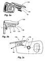
- FIGS. 3a to 3c show an alternative control deflector 130. This can in the embodiment of the Figures 1 and 2 replace the control deflector 30 provided there.
- This second embodiment of a control deflector has a surface portion 138 on its side facing the liquid jet, on which parallel to the outlet direction 4 of the liquid jet guide ribs 144 are provided which extend orthogonally from the surface portion 138.
- These six guide ribs 144 define a total of five intermediate guide channels 142, which are aligned parallel to each other.
- the guide ribs 144 are here as out Figure 3c View is formed so that they have in the direction of the exit direction 4 has a rising depth.
- the guide channels 142 each have a width of about 2 mm and an exit-side depth of also about 2 mm.
- the liquid jet which emerges in the direction of the outlet direction 4 from the corresponding opening of the watering device, inevitably has a slight expansion, which is reinforced in the course of the impact on the surface element 138.
- the guide channels 142 compensate for this expansion by each receiving a portion of the liquid jet and realign this part of the liquid with respect to its direction of movement. Accordingly, at the exit side of the guide channels 142, the liquid exits with a largely uniform direction 5a.
- a erfindungsgze ⁇ e embodiment is in the FIGS. 4a to 4d shown.
- the peculiarity of this Steuerdeflektor 230 of FIGS. 4a to 4d is that although he according to the embodiments of the FIGS. 3a to 3c a plurality of guide channels 242a, 242b, but these are not formed parallel to each other, but to run towards each other. In approximately parallel to the outlet direction 4 of the liquid jet while a Scholeitkanal 242a is aligned.
- a total of six secondary ducts 242b are provided, of which at least some run at an acute angle to the main duct 242a and open into it.
- the guide channels each have an approximately semicircular cross-section.
- the Hautleitkanal 242a has a width of about 3mm and a depth of about 1.5mm.
- the Volunteerleitkanäle 242b are formed slightly smaller.
- This herringbone-like structure means that the liquid jet, which has already been slightly widened as it emerges from the nozzle, which is further widened in the course of the impact on the surface element 238, is recombined to the desired extent.
- the exit of the liquid at the end of the guide channels 242a, 242b in the direction 5b is consequently not only largely parallel, as in the embodiment of FIGS. 3a to 3c , but also as a largely uniform liquid jet.
- FIGS. 4a to 4d Another special feature of the embodiment of the FIGS. 4a to 4d is that the guide channels 242a, 242b are not separated from each other by guide ribs, but are provided as groove-like depressions directly in the surface element 238.
- it is a turbine sprinkler.
- a reduction of the throwing distance can be achieved with other types of sprinklers, for example impulse sprinklers.
Landscapes
- Nozzles (AREA)
- Massaging Devices (AREA)
- Fluid-Driven Valves (AREA)
- Infusion, Injection, And Reservoir Apparatuses (AREA)
- Sink And Installation For Waste Water (AREA)
- Non-Silver Salt Photosensitive Materials And Non-Silver Salt Photography (AREA)
Claims (13)
- Dispositif d'irrigation (10) pour l'irrigation de végétation avec un liquide, dans lequel le dispositif d'irrigation (10) est adapté pour le fonctionnement stationnaire, avec- une buse de sortie (16) de laquelle le liquide peut pendant le fonctionnement sortir dans une direction de sortie (4) sous forme d'un jet de liquide et- un déflecteur de commande (30 ; 130 ; 230) dans une position fixe par rapport à la buse de sortie pendant le fonctionnement,
dans lequel- le déflecteur de commande (230) peut être disposé en ligne dans la direction de sortie (4) du jet de liquide et est adapté pour influencer la direction d'au moins une partie du jet de liquide,- au déflecteur de commande (230) est assigné un dispositif de guidage d'écoulement (142 ; 242a ; 242b) qui peut contrecarrer un déploiement du jet de liquide dans une direction d'extension horizontale transversalement par rapport à la direction du jet,- le dispositif de guidage d'écoulement (242a ; 242b) comprend une surface fonctionnelle (238) pour influencer la direction du jet,- plusieurs canaux de guidage (242a ; 242b) sont prévus sur la surface fonctionnelle (238), disposés ou pouvant être disposés de sorte que le jet de liquide sortant de la buse de sortie (16) peut entrer dans les canaux de guidage (242a ; 242b),et dans lequel les canaux de guidage (242a ; 242b) sont formés par des rainures de guidage (242a, 242b) dans la surface fonctionnelle (238),
caractérisé en ce que
les canaux de guidage (242b) dans la direction de sortie du liquide sont orientés de manière s'étendant les uns vers les autres,
ou en ce que l'arête de la surface fonctionnelle (238) se trouvant dans la zone des extrémités des canaux de guidage (242a ; 242b) est en forme de V, de sorte que la surface fonctionnelle s'étend de plus en plus le long de la direction de sortie du liquide en partant de sa zone médiane allant dans la direction de sortie du liquide, jusqu'à son bord. - Dispositif d'irrigation (10) selon la revendication 1, caractérisé en ce que les canaux de guidage (242a ; 242b)• présentent une profondeur moyenne d'au moins 2 mm, de préférence d'au moins 4 mm et/ou• présentent une largeur inférieure à 5 mm, de préférence inférieure à 3 mm.
- Dispositif d'irrigation (10) selon l'une des revendications 1 ou 2, caractérisé en ce qu'un canal de guidage (242a) est orienté en tant que canal principal approximativement parallèlement à la direction de sortie (4) du jet de liquide.
- Dispositif d'irrigation (10) selon l'une des revendications précédentes, caractérisé en ce que la buse de sortie (16) est orientée de telle sorte que dans la direction de sortie (4) du jet de liquide en sortant, une composante radiale par rapport à un axe principal (2) vertical du dispositif d'irrigation est ainsi déterminée.
- Dispositif d'irrigation (10) selon l'une des revendications précédentes, caractérisé en ce que la buse de sortie (16) et le déflecteur de commande (230) sont réalisés en position fixe l'un par rapport à l'autre, pouvant tourner ensemble autour d'un axe principal (2) vertical du dispositif d'irrigation (10).
- Dispositif d'irrigation (10) selon l'une des revendications précédentes, caractérisé en ce que le déflecteur de commande (230) est réalisé de manière à pouvoir pivoter autour d'un axe horizontal (6) et de préférence à pouvoir être bloqué dans des positions de pivotement libres ou dans des positions de pivotement verrouillées définies.
- Dispositif d'irrigation (10) selon l'une des revendications précédentes, caractérisé en ce que la surface fonctionnelle (238) est prévue en une seule pièce sur le déflecteur de commande (230).
- Dispositif d'irrigation selon l'une des revendications précédentes, caractérisé en ce que la surface fonctionnelle (238) est réalisée de façon inégale.
- Dispositif d'irrigation (10) selon l'une des revendications précédentes, caractérisé en ce que la surface fonctionnelle est réalisée concave.
- Dispositif d'irrigation (10) selon l'une des revendications précédentes, caractérisé en ce que le dispositif de guidage d'écoulement (242a, 242b) est réalisé de telle sorte que la direction de jet est influencée uniquement par rapport à une composante de direction verticale.
- Dispositif d'irrigation (10) selon l'une des revendications précédentes, caractérisé en ce que le dispositif de guidage d'écoulement (242a, 242b) présente une rainure de guidage d'écoulement (242a, 242b) s'étendant dans une direction d'extension principale, dont la direction d'extension principale déploie de préférence avec la direction de sortie du jet de liquide un plan vertical.
- Dispositif d'irrigation (10) selon l'une des revendications précédentes, caractérisé en ce que la rainure de guidage d'écoulement comprend deux surfaces latérales pliées l'une vers l'autre et reliées l'une à l'autre dans une zone de transition, l'angle entre les surfaces latérales étant entre 10° et 170°, de préférence entre 70° et 110°, en particulier 90°.
- Dispositif d'irrigation selon l'une des revendications précédentes, caractérisé en ce que la rainure de guidage d'écoulement (242a, 242b) présente un rayon intérieur moyen inférieur à 6 mm, de préférence inférieur à 4 mm, en particulier inférieur à 1 mm.
Priority Applications (1)
| Application Number | Priority Date | Filing Date | Title |
|---|---|---|---|
| PL10000556T PL2181772T3 (pl) | 2007-03-07 | 2008-03-06 | Urządzenie nawadniające |
Applications Claiming Priority (2)
| Application Number | Priority Date | Filing Date | Title |
|---|---|---|---|
| DE102007012273A DE102007012273A1 (de) | 2007-03-07 | 2007-03-07 | Bewässerungsvorrichtung |
| EP08004136A EP1967279B1 (fr) | 2007-03-07 | 2008-03-06 | Dispositif d'irrigation |
Related Parent Applications (2)
| Application Number | Title | Priority Date | Filing Date |
|---|---|---|---|
| EP08004136 Previously-Filed-Application | 2008-03-06 | ||
| EP08004136.1 Division | 2008-03-06 |
Publications (2)
| Publication Number | Publication Date |
|---|---|
| EP2181772A1 EP2181772A1 (fr) | 2010-05-05 |
| EP2181772B1 true EP2181772B1 (fr) | 2012-05-09 |
Family
ID=39338653
Family Applications (2)
| Application Number | Title | Priority Date | Filing Date |
|---|---|---|---|
| EP10000556A Active EP2181772B1 (fr) | 2007-03-07 | 2008-03-06 | Dispositif d'irrigation |
| EP08004136A Active EP1967279B1 (fr) | 2007-03-07 | 2008-03-06 | Dispositif d'irrigation |
Family Applications After (1)
| Application Number | Title | Priority Date | Filing Date |
|---|---|---|---|
| EP08004136A Active EP1967279B1 (fr) | 2007-03-07 | 2008-03-06 | Dispositif d'irrigation |
Country Status (4)
| Country | Link |
|---|---|
| EP (2) | EP2181772B1 (fr) |
| AT (2) | ATE556780T1 (fr) |
| DE (2) | DE102007012273A1 (fr) |
| PL (2) | PL2181772T3 (fr) |
Families Citing this family (2)
| Publication number | Priority date | Publication date | Assignee | Title |
|---|---|---|---|---|
| EP2651566B1 (fr) * | 2010-12-16 | 2016-10-12 | Husquarna AB | Déflecteur pour un extincteur automatique à eau |
| US11305304B2 (en) | 2018-05-09 | 2022-04-19 | Metzerplas Cooperative Agricultural Organization Ltd. | Rotating sprinkler |
Family Cites Families (10)
| Publication number | Priority date | Publication date | Assignee | Title |
|---|---|---|---|---|
| DE490515C (de) | 1930-01-29 | Georg Bode | Bewaesserungsturbine mit rinnenaehnlichen Fluegeln | |
| CH80782A (de) | 1918-07-31 | 1919-09-16 | Georg Chiogna | Rasensprenger |
| US1778994A (en) * | 1929-11-06 | 1930-10-21 | Joseph H Allen | Lawn-spray-control device |
| US1840721A (en) * | 1930-04-03 | 1932-01-12 | James W Ingram | Rotatable sprinkler |
| DE889236C (de) * | 1951-08-24 | 1953-09-10 | Karl Ludwig Lanninger | Getriebeloser Weitstrahlregner |
| US3391868A (en) * | 1966-02-17 | 1968-07-09 | Ralph D. Cooney | Rotary sprinkler with variable range |
| FR2346968A1 (fr) * | 1976-04-07 | 1977-11-04 | Mangon Michel | Arroseur projecteur rotatif et secteurs a grandes portees variables de liquide en brouillard continu |
| US4984740A (en) * | 1989-06-19 | 1991-01-15 | Hodge Robert B | Water sprinkler with variable stream-distance adjustment |
| IL121726A (en) * | 1997-09-09 | 2001-09-13 | Mamtirim Dan | Strip pattern irrigating sprinkler |
| US7234652B2 (en) | 2005-03-30 | 2007-06-26 | Robert Rodeman | Double curved surface deflector system for rotary sprinklers |
-
2007
- 2007-03-07 DE DE102007012273A patent/DE102007012273A1/de not_active Withdrawn
-
2008
- 2008-03-06 AT AT10000556T patent/ATE556780T1/de active
- 2008-03-06 EP EP10000556A patent/EP2181772B1/fr active Active
- 2008-03-06 EP EP08004136A patent/EP1967279B1/fr active Active
- 2008-03-06 AT AT08004136T patent/ATE483529T1/de active
- 2008-03-06 PL PL10000556T patent/PL2181772T3/pl unknown
- 2008-03-06 DE DE502008001459T patent/DE502008001459D1/de active Active
- 2008-03-06 PL PL08004136T patent/PL1967279T3/pl unknown
Also Published As
| Publication number | Publication date |
|---|---|
| EP2181772A1 (fr) | 2010-05-05 |
| EP1967279A1 (fr) | 2008-09-10 |
| DE102007012273A1 (de) | 2008-09-11 |
| ATE483529T1 (de) | 2010-10-15 |
| ATE556780T1 (de) | 2012-05-15 |
| PL2181772T3 (pl) | 2012-11-30 |
| PL1967279T3 (pl) | 2011-03-31 |
| EP1967279B1 (fr) | 2010-10-06 |
| DE502008001459D1 (de) | 2010-11-18 |
Similar Documents
| Publication | Publication Date | Title |
|---|---|---|
| EP0826426B1 (fr) | Arroseur | |
| DE102011000344B4 (de) | Anordnung zur Verstellung der Düsen eines Sprinklers | |
| DE2819945C2 (de) | Gerät zum Versprühen von Flüssigkeit | |
| DE60320687T2 (de) | Belüftungsdüse für Lüftungssysteme | |
| EP0970752B1 (fr) | dispositif d'arrosage | |
| EP0301367A2 (fr) | Appareil d'arrosage | |
| DE2711448A1 (de) | Sprenger | |
| EP0970753B1 (fr) | Méthode de régler le façon de distribution d'eau d'un arroseur et arroseur | |
| DE1400729A1 (de) | Verspruehvorrichtung fuer Fluessigkeiten | |
| DE2736314C3 (de) | Düse zum Versprühen eines unter Druck stehenden Mediums | |
| DE2906023C3 (de) | Schlaghebelregner | |
| EP2181772B1 (fr) | Dispositif d'irrigation | |
| EP1502653B1 (fr) | Buse de pulvérisation d'un fluide sur une suface | |
| EP1469947B1 (fr) | Ensemble d'arrosage | |
| EP1853770B1 (fr) | Robinetterie de distribution d'eau sanitaire comprenant un dispositif de direction du jet permettant de devier l'ecoulement de l'eau sortant | |
| DE102004001222B4 (de) | Düseneinheit und Gargerät mit einer Düseneinheit | |
| EP4556129A1 (fr) | Dispositif de pulvérisation | |
| DE1559665C3 (fr) | ||
| AT525866A2 (de) | Düse und regner für das zentrale pivot-ende | |
| DE2834243C2 (de) | Luftauslaßdüse für elektrisch betriebene Haartrockner | |
| DE3924794C2 (de) | Spritzdüse, insbesondere für Bewässerungsregner | |
| EP4557935A1 (fr) | Dispositif d'écoulement pour guider au moins partiellement un écoulement de matériau à transporter, tête de distributeur pour une machine d'épandage agricole, et machine d'épandage agricole | |
| DE202007014407U1 (de) | Sprühdüse mit der Möglichkeit zum allseitigen Sprühen von Wasser | |
| DE202004014604U1 (de) | Sprinkler mit bewegbaren Düsen | |
| DE2626948B2 (de) | Vorrichtung zum Verspritzen von Wasser in Wasserrückkühlanlagen |
Legal Events
| Date | Code | Title | Description |
|---|---|---|---|
| PUAI | Public reference made under article 153(3) epc to a published international application that has entered the european phase |
Free format text: ORIGINAL CODE: 0009012 |
|
| AC | Divisional application: reference to earlier application |
Ref document number: 1967279 Country of ref document: EP Kind code of ref document: P |
|
| AK | Designated contracting states |
Kind code of ref document: A1 Designated state(s): AT BE BG CH CY CZ DE DK EE ES FI FR GB GR HR HU IE IS IT LI LT LU LV MC MT NL NO PL PT RO SE SI SK TR |
|
| AX | Request for extension of the european patent |
Extension state: AL BA MK RS |
|
| RIN1 | Information on inventor provided before grant (corrected) |
Inventor name: BISCHLER, EUGEN Inventor name: RENNER, THOMAS Inventor name: SCHIEDT, CHRISTOPH Inventor name: FREY, REINER |
|
| 17P | Request for examination filed |
Effective date: 20101105 |
|
| RIC1 | Information provided on ipc code assigned before grant |
Ipc: B05B 3/02 20060101AFI20111013BHEP Ipc: B05B 3/04 20060101ALN20111013BHEP Ipc: B05B 1/26 20060101ALI20111013BHEP |
|
| GRAP | Despatch of communication of intention to grant a patent |
Free format text: ORIGINAL CODE: EPIDOSNIGR1 |
|
| RIC1 | Information provided on ipc code assigned before grant |
Ipc: B05B 1/26 20060101ALI20111021BHEP Ipc: B05B 3/02 20060101AFI20111021BHEP Ipc: B05B 3/04 20060101ALN20111021BHEP |
|
| GRAS | Grant fee paid |
Free format text: ORIGINAL CODE: EPIDOSNIGR3 |
|
| GRAA | (expected) grant |
Free format text: ORIGINAL CODE: 0009210 |
|
| AC | Divisional application: reference to earlier application |
Ref document number: 1967279 Country of ref document: EP Kind code of ref document: P |
|
| AK | Designated contracting states |
Kind code of ref document: B1 Designated state(s): AT BE BG CH CY CZ DE DK EE ES FI FR GB GR HR HU IE IS IT LI LT LU LV MC MT NL NO PL PT RO SE SI SK TR |
|
| REG | Reference to a national code |
Ref country code: GB Ref legal event code: FG4D Free format text: NOT ENGLISH |
|
| REG | Reference to a national code |
Ref country code: AT Ref legal event code: REF Ref document number: 556780 Country of ref document: AT Kind code of ref document: T Effective date: 20120515 Ref country code: CH Ref legal event code: EP |
|
| REG | Reference to a national code |
Ref country code: IE Ref legal event code: FG4D Free format text: LANGUAGE OF EP DOCUMENT: GERMAN |
|
| REG | Reference to a national code |
Ref country code: DE Ref legal event code: R096 Ref document number: 502008007165 Country of ref document: DE Effective date: 20120705 |
|
| REG | Reference to a national code |
Ref country code: NL Ref legal event code: VDEP Effective date: 20120509 |
|
| REG | Reference to a national code |
Ref country code: LT Ref legal event code: MG4D Effective date: 20120523 |
|
| PG25 | Lapsed in a contracting state [announced via postgrant information from national office to epo] |
Ref country code: FI Free format text: LAPSE BECAUSE OF FAILURE TO SUBMIT A TRANSLATION OF THE DESCRIPTION OR TO PAY THE FEE WITHIN THE PRESCRIBED TIME-LIMIT Effective date: 20120509 Ref country code: CY Free format text: LAPSE BECAUSE OF FAILURE TO SUBMIT A TRANSLATION OF THE DESCRIPTION OR TO PAY THE FEE WITHIN THE PRESCRIBED TIME-LIMIT Effective date: 20120509 Ref country code: NO Free format text: LAPSE BECAUSE OF FAILURE TO SUBMIT A TRANSLATION OF THE DESCRIPTION OR TO PAY THE FEE WITHIN THE PRESCRIBED TIME-LIMIT Effective date: 20120809 Ref country code: LT Free format text: LAPSE BECAUSE OF FAILURE TO SUBMIT A TRANSLATION OF THE DESCRIPTION OR TO PAY THE FEE WITHIN THE PRESCRIBED TIME-LIMIT Effective date: 20120509 Ref country code: IS Free format text: LAPSE BECAUSE OF FAILURE TO SUBMIT A TRANSLATION OF THE DESCRIPTION OR TO PAY THE FEE WITHIN THE PRESCRIBED TIME-LIMIT Effective date: 20120909 Ref country code: SE Free format text: LAPSE BECAUSE OF FAILURE TO SUBMIT A TRANSLATION OF THE DESCRIPTION OR TO PAY THE FEE WITHIN THE PRESCRIBED TIME-LIMIT Effective date: 20120509 |
|
| PG25 | Lapsed in a contracting state [announced via postgrant information from national office to epo] |
Ref country code: HR Free format text: LAPSE BECAUSE OF FAILURE TO SUBMIT A TRANSLATION OF THE DESCRIPTION OR TO PAY THE FEE WITHIN THE PRESCRIBED TIME-LIMIT Effective date: 20120509 Ref country code: LV Free format text: LAPSE BECAUSE OF FAILURE TO SUBMIT A TRANSLATION OF THE DESCRIPTION OR TO PAY THE FEE WITHIN THE PRESCRIBED TIME-LIMIT Effective date: 20120509 Ref country code: SI Free format text: LAPSE BECAUSE OF FAILURE TO SUBMIT A TRANSLATION OF THE DESCRIPTION OR TO PAY THE FEE WITHIN THE PRESCRIBED TIME-LIMIT Effective date: 20120509 Ref country code: GR Free format text: LAPSE BECAUSE OF FAILURE TO SUBMIT A TRANSLATION OF THE DESCRIPTION OR TO PAY THE FEE WITHIN THE PRESCRIBED TIME-LIMIT Effective date: 20120810 Ref country code: PT Free format text: LAPSE BECAUSE OF FAILURE TO SUBMIT A TRANSLATION OF THE DESCRIPTION OR TO PAY THE FEE WITHIN THE PRESCRIBED TIME-LIMIT Effective date: 20120910 |
|
| REG | Reference to a national code |
Ref country code: PL Ref legal event code: T3 |
|
| PG25 | Lapsed in a contracting state [announced via postgrant information from national office to epo] |
Ref country code: CZ Free format text: LAPSE BECAUSE OF FAILURE TO SUBMIT A TRANSLATION OF THE DESCRIPTION OR TO PAY THE FEE WITHIN THE PRESCRIBED TIME-LIMIT Effective date: 20120509 Ref country code: SK Free format text: LAPSE BECAUSE OF FAILURE TO SUBMIT A TRANSLATION OF THE DESCRIPTION OR TO PAY THE FEE WITHIN THE PRESCRIBED TIME-LIMIT Effective date: 20120509 Ref country code: NL Free format text: LAPSE BECAUSE OF FAILURE TO SUBMIT A TRANSLATION OF THE DESCRIPTION OR TO PAY THE FEE WITHIN THE PRESCRIBED TIME-LIMIT Effective date: 20120509 Ref country code: RO Free format text: LAPSE BECAUSE OF FAILURE TO SUBMIT A TRANSLATION OF THE DESCRIPTION OR TO PAY THE FEE WITHIN THE PRESCRIBED TIME-LIMIT Effective date: 20120509 Ref country code: EE Free format text: LAPSE BECAUSE OF FAILURE TO SUBMIT A TRANSLATION OF THE DESCRIPTION OR TO PAY THE FEE WITHIN THE PRESCRIBED TIME-LIMIT Effective date: 20120509 Ref country code: DK Free format text: LAPSE BECAUSE OF FAILURE TO SUBMIT A TRANSLATION OF THE DESCRIPTION OR TO PAY THE FEE WITHIN THE PRESCRIBED TIME-LIMIT Effective date: 20120509 |
|
| PG25 | Lapsed in a contracting state [announced via postgrant information from national office to epo] |
Ref country code: IT Free format text: LAPSE BECAUSE OF FAILURE TO SUBMIT A TRANSLATION OF THE DESCRIPTION OR TO PAY THE FEE WITHIN THE PRESCRIBED TIME-LIMIT Effective date: 20120509 |
|
| PLBE | No opposition filed within time limit |
Free format text: ORIGINAL CODE: 0009261 |
|
| STAA | Information on the status of an ep patent application or granted ep patent |
Free format text: STATUS: NO OPPOSITION FILED WITHIN TIME LIMIT |
|
| 26N | No opposition filed |
Effective date: 20130212 |
|
| PG25 | Lapsed in a contracting state [announced via postgrant information from national office to epo] |
Ref country code: ES Free format text: LAPSE BECAUSE OF FAILURE TO SUBMIT A TRANSLATION OF THE DESCRIPTION OR TO PAY THE FEE WITHIN THE PRESCRIBED TIME-LIMIT Effective date: 20120820 |
|
| PGRI | Patent reinstated in contracting state [announced from national office to epo] |
Ref country code: IT Effective date: 20130401 |
|
| REG | Reference to a national code |
Ref country code: DE Ref legal event code: R097 Ref document number: 502008007165 Country of ref document: DE Effective date: 20130212 |
|
| PG25 | Lapsed in a contracting state [announced via postgrant information from national office to epo] |
Ref country code: BG Free format text: LAPSE BECAUSE OF FAILURE TO SUBMIT A TRANSLATION OF THE DESCRIPTION OR TO PAY THE FEE WITHIN THE PRESCRIBED TIME-LIMIT Effective date: 20120809 |
|
| BERE | Be: lapsed |
Owner name: GARDENA MANUFACTURING G.M.B.H. Effective date: 20130331 |
|
| PG25 | Lapsed in a contracting state [announced via postgrant information from national office to epo] |
Ref country code: MC Free format text: LAPSE BECAUSE OF NON-PAYMENT OF DUE FEES Effective date: 20130331 |
|
| REG | Reference to a national code |
Ref country code: CH Ref legal event code: PL |
|
| REG | Reference to a national code |
Ref country code: IE Ref legal event code: MM4A |
|
| PG25 | Lapsed in a contracting state [announced via postgrant information from national office to epo] |
Ref country code: LI Free format text: LAPSE BECAUSE OF NON-PAYMENT OF DUE FEES Effective date: 20130331 Ref country code: CH Free format text: LAPSE BECAUSE OF NON-PAYMENT OF DUE FEES Effective date: 20130331 Ref country code: BE Free format text: LAPSE BECAUSE OF NON-PAYMENT OF DUE FEES Effective date: 20130331 Ref country code: IE Free format text: LAPSE BECAUSE OF NON-PAYMENT OF DUE FEES Effective date: 20130306 |
|
| REG | Reference to a national code |
Ref country code: GB Ref legal event code: 732E Free format text: REGISTERED BETWEEN 20140403 AND 20140409 |
|
| REG | Reference to a national code |
Ref country code: FR Ref legal event code: TP Owner name: HUSQVARNA AB, SE Effective date: 20140407 |
|
| REG | Reference to a national code |
Ref country code: AT Ref legal event code: MM01 Ref document number: 556780 Country of ref document: AT Kind code of ref document: T Effective date: 20130306 |
|
| PG25 | Lapsed in a contracting state [announced via postgrant information from national office to epo] |
Ref country code: MT Free format text: LAPSE BECAUSE OF FAILURE TO SUBMIT A TRANSLATION OF THE DESCRIPTION OR TO PAY THE FEE WITHIN THE PRESCRIBED TIME-LIMIT Effective date: 20120509 |
|
| REG | Reference to a national code |
Ref country code: DE Ref legal event code: R081 Ref document number: 502008007165 Country of ref document: DE Owner name: HUSQVARNA AB, SE Free format text: FORMER OWNER: GARDENA MANUFACTURING GMBH, 89079 ULM, DE Effective date: 20140627 |
|
| PG25 | Lapsed in a contracting state [announced via postgrant information from national office to epo] |
Ref country code: AT Free format text: LAPSE BECAUSE OF NON-PAYMENT OF DUE FEES Effective date: 20130306 |
|
| PG25 | Lapsed in a contracting state [announced via postgrant information from national office to epo] |
Ref country code: TR Free format text: LAPSE BECAUSE OF FAILURE TO SUBMIT A TRANSLATION OF THE DESCRIPTION OR TO PAY THE FEE WITHIN THE PRESCRIBED TIME-LIMIT Effective date: 20120509 |
|
| PG25 | Lapsed in a contracting state [announced via postgrant information from national office to epo] |
Ref country code: HU Free format text: LAPSE BECAUSE OF FAILURE TO SUBMIT A TRANSLATION OF THE DESCRIPTION OR TO PAY THE FEE WITHIN THE PRESCRIBED TIME-LIMIT; INVALID AB INITIO Effective date: 20080306 Ref country code: LU Free format text: LAPSE BECAUSE OF NON-PAYMENT OF DUE FEES Effective date: 20130306 |
|
| REG | Reference to a national code |
Ref country code: FR Ref legal event code: PLFP Year of fee payment: 9 |
|
| REG | Reference to a national code |
Ref country code: FR Ref legal event code: PLFP Year of fee payment: 10 |
|
| REG | Reference to a national code |
Ref country code: FR Ref legal event code: PLFP Year of fee payment: 11 |
|
| PGFP | Annual fee paid to national office [announced via postgrant information from national office to epo] |
Ref country code: IT Payment date: 20220121 Year of fee payment: 15 |
|
| PGFP | Annual fee paid to national office [announced via postgrant information from national office to epo] |
Ref country code: FR Payment date: 20230217 Year of fee payment: 16 |
|
| PGFP | Annual fee paid to national office [announced via postgrant information from national office to epo] |
Ref country code: PL Payment date: 20230111 Year of fee payment: 16 Ref country code: GB Payment date: 20230213 Year of fee payment: 16 |
|
| P01 | Opt-out of the competence of the unified patent court (upc) registered |
Effective date: 20230419 |
|
| PG25 | Lapsed in a contracting state [announced via postgrant information from national office to epo] |
Ref country code: IT Free format text: LAPSE BECAUSE OF FAILURE TO SUBMIT A TRANSLATION OF THE DESCRIPTION OR TO PAY THE FEE WITHIN THE PRESCRIBED TIME-LIMIT Effective date: 20230306 |
|
| GBPC | Gb: european patent ceased through non-payment of renewal fee |
Effective date: 20240306 |
|
| PG25 | Lapsed in a contracting state [announced via postgrant information from national office to epo] |
Ref country code: GB Free format text: LAPSE BECAUSE OF NON-PAYMENT OF DUE FEES Effective date: 20240306 |
|
| PG25 | Lapsed in a contracting state [announced via postgrant information from national office to epo] |
Ref country code: FR Free format text: LAPSE BECAUSE OF NON-PAYMENT OF DUE FEES Effective date: 20240331 |
|
| PG25 | Lapsed in a contracting state [announced via postgrant information from national office to epo] |
Ref country code: GB Free format text: LAPSE BECAUSE OF NON-PAYMENT OF DUE FEES Effective date: 20240306 Ref country code: FR Free format text: LAPSE BECAUSE OF NON-PAYMENT OF DUE FEES Effective date: 20240331 |
|
| PG25 | Lapsed in a contracting state [announced via postgrant information from national office to epo] |
Ref country code: PL Free format text: LAPSE BECAUSE OF NON-PAYMENT OF DUE FEES Effective date: 20240306 |
|
| PGFP | Annual fee paid to national office [announced via postgrant information from national office to epo] |
Ref country code: DE Payment date: 20260216 Year of fee payment: 19 |