EP2181925A1 - Automatic strapping packing machine and automatic strapping packing system - Google Patents
Automatic strapping packing machine and automatic strapping packing system Download PDFInfo
- Publication number
- EP2181925A1 EP2181925A1 EP08791025A EP08791025A EP2181925A1 EP 2181925 A1 EP2181925 A1 EP 2181925A1 EP 08791025 A EP08791025 A EP 08791025A EP 08791025 A EP08791025 A EP 08791025A EP 2181925 A1 EP2181925 A1 EP 2181925A1
- Authority
- EP
- European Patent Office
- Prior art keywords
- packed
- packing machine
- automatic banding
- band guide
- banding packing
- Prior art date
- Legal status (The legal status is an assumption and is not a legal conclusion. Google has not performed a legal analysis and makes no representation as to the accuracy of the status listed.)
- Withdrawn
Links
- 238000012856 packing Methods 0.000 title claims abstract description 288
- 238000011144 upstream manufacturing Methods 0.000 claims description 11
- 238000009434 installation Methods 0.000 abstract description 6
- 238000003466 welding Methods 0.000 description 5
- 230000002787 reinforcement Effects 0.000 description 2
- 230000000694 effects Effects 0.000 description 1
Images


Classifications
-
- B—PERFORMING OPERATIONS; TRANSPORTING
- B65—CONVEYING; PACKING; STORING; HANDLING THIN OR FILAMENTARY MATERIAL
- B65B—MACHINES, APPARATUS OR DEVICES FOR, OR METHODS OF, PACKAGING ARTICLES OR MATERIALS; UNPACKING
- B65B13/00—Bundling articles
- B65B13/02—Applying and securing binding material around articles or groups of articles, e.g. using strings, wires, strips, bands or tapes
- B65B13/04—Applying and securing binding material around articles or groups of articles, e.g. using strings, wires, strips, bands or tapes with means for guiding the binding material around the articles prior to severing from supply
- B65B13/14—Pairs of carriers or guides movable around opposite sides of the articles
-
- B—PERFORMING OPERATIONS; TRANSPORTING
- B65—CONVEYING; PACKING; STORING; HANDLING THIN OR FILAMENTARY MATERIAL
- B65B—MACHINES, APPARATUS OR DEVICES FOR, OR METHODS OF, PACKAGING ARTICLES OR MATERIALS; UNPACKING
- B65B65/00—Details peculiar to packaging machines and not otherwise provided for; Arrangements of such details
- B65B65/003—Packaging lines, e.g. general layout
-
- B—PERFORMING OPERATIONS; TRANSPORTING
- B65—CONVEYING; PACKING; STORING; HANDLING THIN OR FILAMENTARY MATERIAL
- B65B—MACHINES, APPARATUS OR DEVICES FOR, OR METHODS OF, PACKAGING ARTICLES OR MATERIALS; UNPACKING
- B65B13/00—Bundling articles
- B65B13/02—Applying and securing binding material around articles or groups of articles, e.g. using strings, wires, strips, bands or tapes
- B65B13/04—Applying and securing binding material around articles or groups of articles, e.g. using strings, wires, strips, bands or tapes with means for guiding the binding material around the articles prior to severing from supply
- B65B13/06—Stationary ducts or channels
-
- B—PERFORMING OPERATIONS; TRANSPORTING
- B65—CONVEYING; PACKING; STORING; HANDLING THIN OR FILAMENTARY MATERIAL
- B65B—MACHINES, APPARATUS OR DEVICES FOR, OR METHODS OF, PACKAGING ARTICLES OR MATERIALS; UNPACKING
- B65B13/00—Bundling articles
- B65B13/18—Details of, or auxiliary devices used in, bundling machines or bundling tools
Definitions
- the first carry-in apparatus 206 and the first carry-out apparatus 208 of the first conveying line 204 constituted by a conveyer and the like should be arranged in a direction orthogonal to the upper arch 210 for the first automatic banding packing machine 202.
- the band guide arch 302 of the first automatic banding packing machine 300 is arranged in the lying down state on the upper-face table 306 as shown by the virtual line in Figs. 15 and 16 .
- an object to be packed 318 having been conveyed in an arrow direction on the first conveying line 312 does not contact the band guide arch 302 or obstruct feeding.
- the present invention was made in view of the circumstances and has an object to provide an automatic banding packing machine and its automatic banding packing system in which conveying lines of an object to be packed can be aligned in a straight direction, an installation space can be small, an entire structure can be simplified, and moreover, band supply into a band guide arch can be performed surely and continuous packing work is possible.
- the automatic banding packing machine of the present invention is characterized in that the horizontal band guide arch is configured capable of moving its position in a direction orthogonal to the passage direction of the object to be packed above the upper-face table.
- the cross-state banding can be performed, and the automatic banding packing machine and another automatic banding packing machine can be arranged in a straight line state, not in a right angle state as before, which can make an installation space small and moreover, simplify the entire structure.
- the one automatic banding packing machine for banding in parallel with the passage direction of the object to be packed and the other banding packing machine for banding the object to be packed in the direction orthogonal to the passage direction of the object to be packed of the one automatic banding packing machine can be freely arranged on the upstream side or the downstream side, freedom of design is improved.
- the horizontal band guide arch by moving the horizontal band guide arch to an arbitrary position in the direction orthogonal to the passage direction of the object to be packed above the upper-face table and by moving the pair of vertical band guide arches arranged separately from each other from the standby position to the communication position communicating with the horizontal band guide arch for performing banding, at an arbitrary position in the direction orthogonal to the passage direction of the object to be packed, the obj ect to be packed can be banded in parallel with the passage direction of the object to be packed.
- the object to be packed can be banded in parallel with the passage direction of the object to be packed at arbitrary plural positions in the direction orthogonal to the passage direction of the object to be packed.
- the object to be packed can be banded in parallel with the passage direction of the object to be packed and by the other automatic banding packing machine, the object to be packed can be banded and bundled in the direction orthogonal to the passage direction of the object to be packed of the one automatic banding packing machine, and the object to be packed can be banded in the cross state.
- a left end side of a right-side rotating bar 40 is rotatably pin-connected, and at a right end side of the right-side rotating bar 40, an upper end of the right-side vertical band guide arch 36 is fixed.
- the right-side vertical band guide arch 36 integrated with the right-side rotating bar 40 is moved to the standby position retreated to a position close to the right-side rear frame 20
- the left-side vertical band guide arch 38 integrated with the left-side rotating bar 42 is moved to the standby position retreated to a position close to the left-side rear frame 24.
- banding can be performed in parallel with the passage direction of the object to be packed, and firmer banding can be realized.
- the horizontal band guide arch 32 may be arranged in plural in the direction orthogonal to the passage direction of the object to be packed.
- the vertical band guide arches 36, 38 of the one automatic banding packing machine 74 are moved to the standby position in advance (position indicated by a dotted line in Fig. 9 ).
- the object to be packed 72 is banded in the direction parallel with the passage direction of the object to be packed 72 of the one automatic banding packing machine 74 (front and rear direction in Fig. 9 ) for performing banding in the cross state (See the object to be packed 72 on the third conveying line 82 in Fig. 9 ).
- the other automatic banding packing machine 76 may be constituted by the automatic banding packing machine 10 of the present invention.
Landscapes
- Engineering & Computer Science (AREA)
- Mechanical Engineering (AREA)
- Basic Packing Technique (AREA)
Abstract
Solving Means:
The automatic banding packing machine is provided with a packing machine body having an upper-face table on which the object to be packed passes, a pair of vertical band guide arches arranged separately from each other above the upper-face table in a direction parallel with a passage direction of the object to be packed, and a horizontal band guide arch arranged above the upper-face table in the direction parallel with the passage direction of the object to be packed, and the pair of vertical band guide arches is configured to be movable between a standby position separated from the horizontal band guide arch and a communication position communicating with the horizontal band guide arch in a direction orthogonal to the passage direction of the object to be packed.
Description
- The present invention relates to an automatic banding packing machine and an automatic banding packing system.
- With a trend of labor saving in a packing work, an automatic
banding packing machine 100 as shown inFig. 12 has been widely used as disclosed in the Patent Document 1 (Japanese Patent Laid-Open Publication No.H5(1993)-112315 - That is, the automatic
banding packing machine 100 is, as shown inFig. 12 , provided with apacking machine body 101 installed on a floor face of a plant and the like, for example, and on an upper face of thepacking machine body 101, an upper-face table 114 constituting a work base for mounting and packing an object to be packed is formed. - And on the upper-face table 114, a
band guide arch 102 substantially in the U-shape is installed upright and a continuous band passage is formed therein, though not shown. - That is, the
band guide arch 102 is constituted by a pair ofvertical arches upper arch 108 connecting upper end portions of thevertical arches - On the other hand, on the upper-face table 114, a
guide groove 110 in a narrow groove state is formed across the substantially center part, and theguide groove 110 communicates with the band passage formed within theband guide arch 102. - In such automatic
banding packing machine 100, by setting the object to be packed within a frame of theband guide arch 102, a band is fed out by a band feeding mechanism, not shown, with a subsequent button operation from areel 112 around which the band is wound to the band passage of theband arch 102 comprising thevertical arches upper arch 108 through theguide groove 110, and a series of packing works including band pulling-back, band fastening, and further welding carried out substantially at the same time as cutting are all automatically performed. - In a delivery plant of articles and the like, cross-like banding is performed on an object to be packed in some cases.
- In this case, an automatic
banding packing system 200 arranged on a conveying line is used with two units of the automaticbanding packing machines 100 with the conventional configuration as shown inFig. 12 . - That is, as shown in
Fig. 13 , on the upstream side of the automaticbanding packing system 200, a first automaticbanding packing machine 202 for first banding is arranged, and afirst conveying line 204 is connected to the first automaticbanding packing machine 202. - The
first conveying line 204 is constituted by a conveyor and the like, for example, and comprises a first carry-inapparatus 206 connected to a carry-in side of the first automaticbanding packing machine 202 and a first carry-out apparatus 208 connected to a carry-out side of the first automaticbanding packing machine 202. - And the first automatic
banding packing machine 202 is arranged so that a conveying direction of thefirst conveying line 204, that is, the conveying direction of the first carry-inapparatus 206 and the first carry-outapparatus 208 crosses an arch direction of anupper arch 210 of the first automaticbanding packing machine 202 at a right angle. - On the downstream side of the automatic
banding packing system 200, a second automaticbanding packing machine 212 for subsequent banding is arranged, and asecond conveying line 214 is connected to the second automaticbanding packing machine 212. - The
second conveying line 214 is constituted by a conveyer and the like, for example, and comprises a second carry-inapparatus 216 connected to a carry-in side of the second automaticbanding packing machine 212 and a second carry-out apparatus 218 connected to a carry-out side of the second automaticbanding packing machine 212. - And the second automatic
banding packing machine 212 is arranged so that the conveying direction of thesecond conveying line 214, that is, the conveying direction of the second carry-inapparatus 216 and the second carry-outapparatus 218 crosses the arch direction of anupper arch 220 of the second automaticbanding packing machine 212 at a right angle. - In this automatic
banding packing system 200, as shown inFig. 13 , the conveying direction of thefirst conveying line 204 and thesecond conveying line 214 are connected so that they cross each other at a right angle. - Therefore, in the automatic
banding packing system 200 constituted as above, a packing work is carried out as follows. - First, an object to be packed 224 is sequentially delivered by the first carry-in
apparatus 208 of thefirst conveying line 204 as shown by an arrow inFig. 13 and carried into the first automaticbanding packing machine 202. And at this first automaticbanding packing machine 202, first banding is performed in a direction orthogonal to the conveying direction of the first conveying line 204 (See the object to be packed 224 in the lower right ofFig. 13 ). - Subsequently, through the first carry-out
apparatus 208 of thefirst conveying line 204, the object to be packed 224 on which the first banding has been performed is carried out from the first automaticbanding packing machine 202 and transferred onto the second carry-inapparatus 216 of the second conveyingline 214 on the downstream side, located on the downstream side of thefirst conveying line 204 and arranged at a right angle with thefirst conveying line 204, through a transfer apparatus such as a traverser, not shown. - And at the first automatic
banding packing machine 202, the object to be packed 224 on which the first banding has been performed is conveyed over the second carry-inapparatus 216 as shown by an arrow inFig. 13 and carried into the second automaticbanding packing machine 212 performing the subsequent banding in a cross state in a direction orthogonal to the direction of the first banding. - And at the second automatic
banding packing machine 212, banding is performed in a direction orthogonal to the conveying direction of the second carry-inapparatus 216 and as shown in the object to be packed 224 in the upper right ofFig. 13 , the cross-state banding is performed on the object to be packed 224. - However, with such conventional automatic banding packing system shown in
Fig. 13 , it is necessary as mentioned above that thefirst conveying line 204 and thesecond conveying line 214 orthogonal to each other are provided, and the first automaticbanding packing machine 202 for performing the first banding and the second automaticbanding packing machine 212 for performing the subsequent banding are provided on thefirst conveying line 204 and thesecond conveying line 214, respectively. - That is, as shown in
Fig. 13 , when two units of the first automaticbanding packing machine 202 and the second automaticbanding packing machine 212 are used, the first carry-inapparatus 206 and the first carry-out apparatus 208 of thefirst conveying line 204 constituted by a conveyer and the like should be arranged in a direction orthogonal to theupper arch 210 for the first automaticbanding packing machine 202. - Also for the second automatic
banding packing machine 212, the second carry-inapparatus 216 and the second carry-out apparatus 218 of thesecond conveying line 214 should be arranged in a direction orthogonal to theupper arch 220. Moreover, a transfer apparatus such as a traverser is required between thefirst conveying line 204 and thesecond conveying line 214. - As mentioned above, in the case of the cross-state banding on the object to be packed 224 in a mode of
Fig. 13 , since it is necessary to arrange thefirst conveying line 204 and thesecond conveying line 214 in directions orthogonal to each other, a large installation space for installing thefirst conveying line 204 and thesecond conveying line 214 is needed, a transfer apparatus such as a traverser is separately required, and apparatus configuration becomes complicated, which are problems. - In order to solve such a problem of space, an automatic banding packing system can be configured, as shown in
Fig. 14 , by aligning thefirst conveying line 204 and thesecond conveying line 214 in a straight direction. - However, in this case, as shown in
Fig. 14 , theupper arch 220 of aband guide arch 222 of the second automaticbanding packing machine 212 performing the subsequent banding is arranged in parallel with the conveying direction of thesecond conveying line 214. - Thus, even if the object to be packed 224 on which the first banding has been performed is to be conveyed over the second carry-in
apparatus 216 and carried into the second automaticbanding packing machine 212, a vertical arch part of theband guide arch 222 of the second automaticbanding packing machine 212 is on the way and the object to be packed 224 can not be carried into the second automaticbanding packing machine 212, and the subsequent banding is impossible. - In order to solve the above problem, the Patent Document 2 (Japanese Patent Laid-Open Publication No.
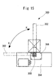
2006-290431 Fig. 15 . - That is, as shown in
Fig. 15 , in this automaticbanding packing machine 300, aband guide arch 302 of the automaticbanding packing machine 300 is configured capable of tilting in a direction of an arrow A-A' with respect to an upper-face table 306 of apacking machine body 304 and is usually used in an upright state to the upper-face table 306. - That is, the
band guide arch 302 is rotatably supported by a rotatingshaft 308 arranged at a position somewhat lower than a top face of the upper-face table 306 and by tilting it in a direction of an arrow A with the rotatingshaft 308 as a fulcrum through a tilting driving mechanism, not shown, the entire arch is arranged along the upper face of the upper-face table 306. - And banding is performed when the
band guide arch 302 is in a standing attitude in the vertical direction as shown by a solid line inFig. 15 , and it can be tilted in an attitude of lying down by 90° as shown by a virtual line as necessary. - Also, the Patent Document 2 proposes configuration of an automatic
banding packing system 320 by using one unit of an automaticbanding packing machine 300 with the structure as shown inFig. 15 and one unit of a usual second automaticbanding packing machine 310 with the structure as shown inFig. 12 mentioned above and by aligning afirst conveying line 312, asecond conveying line 314, and athird conveying line 316 in a straight direction as shown inFig. 16 . - That is, first, the
band guide arch 302 of the first automaticbanding packing machine 300 is arranged in the lying down state on the upper-face table 306 as shown by the virtual line inFigs. 15 and16 . In a state where theband guide arch 302 is arranged in the laying down state, an object to be packed 318 having been conveyed in an arrow direction on thefirst conveying line 312 does not contact theband guide arch 302 or obstruct feeding. - And by detecting a fact that the object to be packed 318 has been carried into the first automatic
banding packing machine 300 and has reached onto the upper-face table 306 by detecting the object to be packed 318 with detecting means such as a photoelectric tube, not shown, for example, theband guide arch 302 is rotated in a direction of an arrow A' by driving means such as a motor or an air cylinder to bring theband guide arch 302 into an upright state. - In a state where the
band guide arch 302 is in a usually upright state as above, the first banding is performed in a direction parallel with the conveying direction of the first conveying line 312 (See the object to be packed 318 over thesecond conveying line 314 inFig. 16 ). - Subsequently, at the automatic
banding packing machine 300, it is so configured that the object to be packed 318 on which the first banding has been performed is conveyed over thesecond conveying line 314 and at the second automaticbanding packing machine 310, the banding is performed in a direction orthogonal to thesecond conveying line 314 and the cross-state banding is performed on the object to be packed 318 and the object is carried out by the third conveying line 316 (See the object to be packed 318 on thethird conveying line 316 inFig. 16 ). - In the Patent Document 3 (Japanese Patent Laid-Open Publication No.
2006-315746 Fig. 17 , an automaticbanding packing machine 400 with another configuration is proposed, and at this automaticbanding packing machine 400, aband guide arch 402 is installed upright with bias to the rear of an upper-face table 404. - And such automatic
banding packing machine 400 is proposed in which acenter bar 408 capable of tilting is provided at a region below ahorizontal arch 406 of theband guide arch 402, and a band pulled back into apacking machine body 410 from theband guide arch 402 is received by thecenter bar 408 and then, dropped below. - On the other hand, the Patent Document 4 (Japanese Patent Laid-Open Publication No.
S61(1986)-127410 banding packing machine 500 as shown inFig. 18 . - That is, this automatic
banding packing machine 500 uses twoarches packing machine body 502, in which theinner arch 504 of them is installed upright close to the center of thepacking machine body 502 so that a band revolves in the arch for packing, while the otherouter arch 506 is arranged so as to cross theinner arch 504 at a right angle. - It is so configured that a vertical arm of the
outer arch 506 is located at a position not obstructing ingress of an object to be packed 516 into thepacking machine body 502, and the vertical arm of theouter arch 506 is moved to a position for packing after the ingress, the band revolves inside, and the band of theouter arch 506 crosses the band of theinner arch 504 vertically so that the object to be packed 516 can be packed. - Patent Document 1: Japanese Patent Laid-Open Publication No.
H5(1993)-112315 - Patent Document 2: Japanese Patent Laid-Open Publication No.
2006-290431 - Patent Document 3: Japanese Patent Laid-Open Publication No.
2006-315746 - Patent Document 4: Japanese Patent Laid-Open Publication No.
S61(1986)-127410 - However, with the automatic
banding packing machine 300 of the Patent Document 2, the configuration of the tilting mechanism for tilting theband guide arch 302 is complicated, the apparatus becomes bigger in consideration of durability and safety, and it takes costs, which are problems. - With the automatic
banding packing machine 400 of the Patent Document 3, since theband guide arch 402 is installed upright with bias to the rear of the upper-face table 404, a corner portion is enlarged, and band supply runs short when supplying a band into the band guide arch, which is a problem. - Moreover, with the automatic
banding packing machine 500 of the Patent Document 4 in which theinner arch 504 and the otherouter arch 506 cross each other at a right angle in the cross state, as shown inFig. 18 , configuration in which aprojecting mechanism 508 of theinner arch 504 is fitted with agap portion 510 of theouter arch 506 is required, and moreover, complicated configuration in which a short andsmall band guide 514 in theprojecting mechanism 508 of theinner arch 504 enters in the middle of aband guide 512 of theouter arch 506 and theband guide 512 and the short andsmall band guide 514 communicate with each other and make the band capable of revolving in theouter arch 506 is needed, which takes costs. - The present invention was made in view of the circumstances and has an object to provide an automatic banding packing machine and its automatic banding packing system in which conveying lines of an object to be packed can be aligned in a straight direction, an installation space can be small, an entire structure can be simplified, and moreover, band supply into a band guide arch can be performed surely and continuous packing work is possible.
- The present invention was made in order to solve the problems in the related arts and to achieve the objects, and the automatic banding packing machine of the present invention comprises:
- a packing machine body having an upper-face table on which an object to be packed passes;
- a pair of vertical band guide arches arranged above the upper-face table in a direction parallel with a passage direction of the object to be packed separately from each other; and
- a horizontal band guide arch arranged above the upper-face table in a direction parallel with the passage direction of the object to be packed, wherein
- the pair of vertical band guide arches are configured to be movable between a standby position separated from the horizontal band guide arch in a direction orthogonal to the passage direction of the object to be packed and a communication position communicating with the horizontal band guide arch.
- With configuration as above, when the object to be packed is to be carried into the automatic banding packing machine, by positioning the pair of vertical band guide arches arranged in the direction parallel with the passage direction of the object to be packed separately from each other at the standby position separated from the horizontal band guide arch in the direction orthogonal to the passage direction of the object to be packed, when the object to be packed is carried into the automatic banding packing machine, the vertical band guide arches do not stand in the way but the object can be surely carried into a packing position of the automatic banding packing machine.
- In a state where the object to be packed has been carried into the packing position of the automatic banding packing machine, the pair of vertical band guide arches arranged separately from each other are moved from the standby position to the communication position communicating with the horizontal band guide arch.
- As a result, the pair of vertical band guide arches and the horizontal band guide arch form a U-shaped band guide arch, within which a band passage is formed, and by feeding a band so as to have it pass through the band passage, the band can be surely supplied into the band guide arch.
- In this state, a series of packing works including pulling-back of the band, fastening of the band, and moreover, welding performed substantially at the same time as cutting are all carried out automatically, whereby the object to be packed can be banded in parallel with the direction where the object to be packed passes through.
- Also, the automatic banding packing machine of the present invention is characterized in that the horizontal band guide arch is arranged at an upper side of the vertical band guide arches.
- With such configuration, in a state where the pair of vertical band guide arches have been moved from the standby position to the communication position communicating with the horizontal band guide arch, the U-shaped band guide arch is constituted by the pair of vertical band guide arches and the horizontal band guide arch, inside which the band passage is surely formed.
- As a result, by feeding the band so that the band is passed through the band passage, a series of packing works including pulling-back of the band, fastening of the band, and moreover, welding substantially at the same time as cutting are all automatically carried out, whereby the object to be packed can be banded in parallel with the direction through which the object to be packed is passed.
- Also, the automatic banding packing machine of the present invention is characterized in that the horizontal band guide arch is arranged in a state fixed above the upper-face table.
- With such configuration, there is no need to move the horizontal band guide arch, but it is only necessary to move the pair of vertical band guide arches from the standby position to the communication position communicating with the horizontal band guide arch, which simplifies the apparatus configuration and reduces costs.
- Also, the automatic banding packing machine of the present invention is characterized in that the horizontal band guide arch is configured capable of moving its position in a direction orthogonal to the passage direction of the object to be packed above the upper-face table.
- With such configuration, by moving the horizontal band guide arch to an arbitrary position in a direction orthogonal to the passage direction of the object to be packed above the upper-face table and by moving the pair of vertical band guide arch arranged separately from each other from the standby position to the communication position communicating with the horizontal band guide arch for performing banding, at the arbitrary position in the direction orthogonal to the passage direction of the object to be packed, the object to be packed can be banded in parallel with the direction through which the object to be packed is passed.
- Therefore, at plural positions in the direction orthogonal to the passage direction of the object to be packed, banding can be performed in parallel with the passage direction of the object to be packed so as to ensure firmer banding.
- Also, the automatic banding packing machine of the present invention is characterized in that the horizontal band guide arch is arranged in plural in the direction orthogonal to the passage direction of the object to be packed.
- With such configuration, by moving the pair of vertical band guide arches arranged separately from each other from the standby position to the communication position communicating with the horizontal band guide arches arranged in plural so as to perform banding, respectively, at the arbitrary plural positions in the direction orthogonal to the passage direction of the object to be packed, the object to be packed can be banded in parallel with the passage direction of the object to be packed.
- Therefore, at plural positions in the direction orthogonal to the passage direction of the object to be packed, the obj ect to be packed can be banded in parallel with the passage direction of the object to be packed so as to ensure firmer banding.
- Also, the automatic banding packing machine of the present invention is provided with:
- driving means for moving positions of the pair of vertical band guide arches in a direction orthogonal to the passage direction of the object to be packed, and characterized in that
- the driving means is configured to move the positions of the pair of vertical band guide arches in the direction orthogonal to the passage direction of the object to be packed through a link mechanism connected to between the cylinder and the pair of vertical band guide arches.
- By employing the cylinder and link mechanism as the driving means for moving the positions of the pair of vertical band guide arches in the direction orthogonal to the passage direction of the object to be packed, the pair of vertical band guide arches can be moved to the standby position and the communication position in the direction orthogonal to the passage direction of the object to be packed more surely so as to ensure more accurate banding.
- Also, the automatic banding packing machine of the present invention is provided with:
- driving means for moving positions of the pair of vertical band guide arches in a direction orthogonal to the passage direction of the object to be packed, and characterized in that
- the driving means is configured to move the positions of the pair of vertical band guide arches in the direction orthogonal to the passage direction of the object to be packed through a stepping motor.
- By employing the stepping motor as the driving means for moving the positions of the pair of vertical band guide arches in the direction orthogonal to the passage direction of the object to be packed as mentioned above, the pair of vertical band guide arches can be moved to the standby position and the communication position in the direction orthogonal to the passage direction of the object to be packed more surely so as to ensure more accurate banding.
- Also, the automatic banding packing system of the present invention is an automatic banding packing system for banding an object to be packed in a cross state, in which
two automatic banding packing machines are arranged adjacently so that a passage direction of the object to be packed becomes a straight line,
one of the automatic banding packing machines is configured by the automatic banding packing machine described in any ofclaims 1 to 7, and
the other automatic banding packing machine is configured by an automatic banding packing machine for bundling the object to be packed in a direction orthogonal to the passage direction of the object to be packed of the one automatic banding packing machine. - With such configuration, the object to be packed can be banded by the one automatic banding packing machine in parallel with the passage direction of the object to be packed, and the banding and bundling can be performed on the object to be packed by the other banding packing machine in the direction orthogonal to the passage direction of the object to be packed of the one automatic banding packing machine, so that the cross-state banding can be performed on the object to be packed.
- Moreover, even if the two automatic banding packing machines are arranged adjacently so that the passage direction of the object to be packed is a straight line, the cross-state banding can be performed, and the automatic banding packing machine and another automatic banding packing machine can be arranged in a straight line state, not in a right angle state as before, which can make an installation space small and moreover, simplify the entire structure.
- Also, the automatic banding packing system of the present invention is characterized in that
on an upstream side of a conveying line for conveying the object to be packed, one of the automatic banding packing machines is disposed; and
on a downstream side of the conveying line for conveying the object to be packed, the other automatic banding packing machine is disposed. - Also, the automatic banding packing system of the present invention is characterized in that
on a downstream side of a conveying line for conveying the object to be packed, one of the automatic banding packing machines is disposed; and
on an upstream side of the conveying line for conveying the object to be packed, the other automatic banding packing machine is disposed. - As mentioned above, since the one automatic banding packing machine for banding in parallel with the passage direction of the object to be packed and the other banding packing machine for banding the object to be packed in the direction orthogonal to the passage direction of the object to be packed of the one automatic banding packing machine can be freely arranged on the upstream side or the downstream side, freedom of design is improved.
- Also, the automatic banding packing system of the present invention is characterized in that
the other automatic banding packing machine is constituted by the automatic banding packing machine described in any of the preceding. - With such configuration, by constituting not only the one automatic banding packing machine but also the other automatic banding packing machine by the automatic banding packing machine of the present invention, there is no need to perform the packing work by arranging an automatic banding packing machine with a different structure as before, and its control system does not become complicated but the control system itself is simplified.
- According to the present invention, when an object to be packed is to be carried into an automatic banding packing machine, by positioning a pair of vertical band guide arches arranged separately from each other in a direction parallel with a passage direction of the object to be packed at a standby position separated from a horizontal band guide arch in a direction orthogonal to the passage direction of the object to be packed, the vertical band guide arches do not stand in the way when the object to be packed is carried into the automatic banding packing machine but can be surely carried into a packing position of the automatic banding packing machine.
- And in a state where the object to be packed has been carried into the packing position of the automatic banding packing machine, the pair of vertical band guide arches arranged separately from each other are moved from the standby position to the communication position communicating with the horizontal band guide arch.
- As a result, the pair of vertical band guide arches and the horizontal band guide arch form a U-shaped band guide arch, in which a band passage is surely formed, and by feeding a band so as to have it pass through the band passage, band supply into the band guide arch can be performed surely.
- And in this state, a series of packing works including pulling-back of the band, fastening of the band and moreover, welding substantially at the same time as cutting and the like are all carried out automatically, whereby the object to be packed can be banded in parallel with the passage direction of the object to be packed.
- Also, according to the present invention, there is no need to move the horizontal band guide arch but it is only necessary to move the pair of vertical band guide arches from the standby position to the communication position communicating with the horizontal band guide arch, and the apparatus configuration is simplified and costs can be reduced.
- Also, according to the present invention, by moving the horizontal band guide arch to an arbitrary position in the direction orthogonal to the passage direction of the object to be packed above the upper-face table and by moving the pair of vertical band guide arches arranged separately from each other from the standby position to the communication position communicating with the horizontal band guide arch for performing banding, at an arbitrary position in the direction orthogonal to the passage direction of the object to be packed, the obj ect to be packed can be banded in parallel with the passage direction of the object to be packed.
- Therefore, the object to be packed can be banded in parallel with the passage direction of the object to be packed at plural positions in the direction orthogonal to the passage direction of the object to be packed, which ensures firmer banding.
- Also, according to the present invention, by moving the pair of vertical band guide arches arranged separately from each other from the standby position to the communication position communicating with these horizontal band guide arches arranged in plural for performing banding, respectively, the object to be packed can be banded in parallel with the passage direction of the object to be packed at arbitrary plural positions in the direction orthogonal to the passage direction of the object to be packed.
- Therefore, at plural positions in the direction orthogonal to the passage direction of the object to be packed, the object to be packed can be banded in parallel with the passage direction of the object to be packed, which can realize firmer banding.
- Also, according to the present invention, by employing the cylinder, the link mechanism, and the stepping motor as the deriving means for moving the positions of the pair of vertical band guide arches in the direction orthogonal to the passage direction of the object to be packed, the pair of vertical band guide arches can be moved to the standby position and the communication position in the direction orthogonal to the passage direction of the object to be packed more surely, which ensures accurate banding.
- Also, according to the present invention, by the one automatic banding packing machine, the object to be packed can be banded in parallel with the passage direction of the object to be packed and by the other automatic banding packing machine, the object to be packed can be banded and bundled in the direction orthogonal to the passage direction of the object to be packed of the one automatic banding packing machine, and the object to be packed can be banded in the cross state.
- Moreover, even if the two automatic banding packing machines are arranged adjacently so that the passage direction of the object to be packed becomes a straight line, the cross-state banding is possible and the automatic banding packing machine and another automatic banding packing machine can be arranged in the straight state, not in the right angle state as before, which reduces the installation space and moreover, simplifies the entire structure.
- Also, according to the present invention, since the one automatic banding packing machine for banding in parallel with the passage direction of the object to be packed and the other automatic banding packing machine for banding the object to be packed in the direction orthogonal to the passage direction of the object to be packed of the one automatic banding packing machine can be freely arranged on the upstream side or the downstream side, design freedom is improved.
- Also, according to the present invention, by constituting not only the one automatic banding packing machine but also the other automatic banding packing machine by the automatic banding packing machine of the present invention, since there in no need to arrange the automatic banding packing machine with a different structure for performing the packing work as before, the control system does not become complicated but the control system itself is simplified.
-
- [
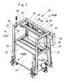
Fig. 1] Fig. 1 is a perspective view illustrating a state where a vertical band guide arch of an automatic banding packing machine of the present invention is located at a standby position. - [
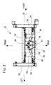
Fig. 2] Fig. 2 is a rear view seen from A-A direction inFig. 1 . - [
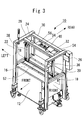
Fig. 3] Fig. 3 is a perspective view illustrating a state where it is located at a communication position of the automatic banding packing machine of the present invention. - [
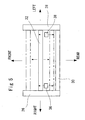
Fig. 4] Fig. 4 is a rear view seen from B-B direction inFig. 3 . - [
Fig. 5] Fig. 5 is an outline top view illustrating another embodiment of the automatic banding packing machine of the present invention. - [
Fig. 6] Fig. 6 is an outline top view illustrating another embodiment of the automatic banding packing machine of the present invention. - [
Fig. 7] Fig. 7 is a perspective view illustrating another embodiment of the automatic banding packing machine of the present invention. - [
Fig. 8] Fig. 8 is a rear view of the automatic banding packing machine inFig. 7 . - [
Fig. 9] Fig. 9 is an outline plan view illustrating an embodiment of an automaticbanding packing system 70 using an automaticbanding packing machine 10 of the present invention. - [
Fig. 10] Fig. 10 is an outline plan view illustrating another embodiment of an automaticbanding packing system 70 using an automaticbanding packing machine 10 of the present invention. - [
Fig. 11] Fig. 11 is an outline plan view illustrating another embodiment of an automaticbanding packing system 70 using an automaticbanding packing machine 10 of the present invention. - [
Fig. 12] Fig. 12 is an outline perspective view of a conventional automatic banding packing machine. - [
Fig. 13] Fig. 13 is a plan view illustrating a disposed situation of a conveying line for cross banding on an object to be packed using the conventional automatic banding packing machine and the automatic banding packing machines. - [
Fig. 14] Fig. 14 is a plan view for explaining nonconformity when the conventional automatic banding packing machines are arranged in a straight line for cross banding on the object to be packed. - [
Fig. 15] Fig. 15 is a partially enlarged side view of the conventional automatic banding packing machine. - [
Fig. 16] Fig. 16 is a plan view illustrating a disposed situation of a conveying line for cross banding on an object to be packed using the conventional automatic banding packing machine and the automatic banding packing machines. - [
Fig. 17] Fig. 17 is a partially enlarged perspective view of the conventional automatic banding packing machine. - [
Fig. 18] Fig. 18 is a front view for explaining an operation of the conventional automatic banding packing machine. -
- 10
- automatic banding packing machine
- 12
- packing machine body
- 16
- upper-face table
- 18
- right-side front frame
- 20
- right-side rear frame
- 22
- left-side front frame
- 24
- left-side rear frame
- 26
- right-side connection bar
- 28
- left-side connection bar
- 30
- rear connection bar
- 32
- horizontal band guide arch
- 34
- support plate
- 36
- right-side vertical band guide arch
- 38
- left-side vertical band guide arch
- 40
- right-side rotating bar
- 42
- left-side rotating bar
- 44
- slide plate
- 46
- right-side link
- 48
- left-side link
- 50
- cylinder device
- 52
- narrow groove
- 54
- reinforcement plate
- 58
- stepping motor
- 62, 64
- rotating shaft
- 66
- rotating bar
- 70
- automatic banding packing system
- 72
- object to be packed
- 74
- one automatic banding packing machine
- 76
- the other automatic banding packing machine
- 78
- first conveying line
- 80
- second conveying line
- 82
- third conveying line
- 100
- automatic banding packing machine
- 101
- packing machine body
- 102
- band guide arch
- 104, 106
- vertical arch
- 108
- upper arch
- 110
- guide groove
- 112
- reel
- 114
- upper-face table
- 200
- automatic banding packing system
- 202
- first automatic banding packing machine
- 204
- first conveying line
- 206
- first carry-in apparatus
- 208
- first carry-out apparatus
- 210
- upper arch
- 212
- second automatic banding packing machine
- 214
- second conveying line
- 216
- second carry-in apparatus
- 218
- second carry-out apparatus
- 220
- upper arch
- 222
- band guide arch
- 224
- object to be packed
- 300
- automatic banding packing machine
- 302
- band guide arch
- 304
- packing machine body
- 306
- upper-face table
- 308
- rotating shaft
- 310
- second automatic banding packing machine
- 312
- first conveying line
- 314
- second conveying line
- 316
- third conveying line
- 318
- object to be packed
- 320
- automatic banding packing system
- 400
- automatic banding packing machine
- 402
- band guide arch
- 404
- upper-face table
- 406
- horizontal arch
- 408
- center bar
- 410
- packing machine body
- 500
- automatic banding packing machine
- 502
- packing machine body
- 504
- inner arch
- 506
- outer arch
- 508
- projecting mechanism
- 510
- gap portion
- 512
- band guide
- 514
- short and small band guide
- 516
- object to be packed
- An embodiment (example) of the present invention will be described below in more detail based on the attached drawings.
-
Fig. 1 is a perspective view illustrating a state where the vertical band guide arch of the automatic banding packing machine of the present invention is located at a standby position,Fig. 2 is a rear view seen from A-A direction inFig. 1 ,Fig. 3 is a perspective view illustrating a state where it is, located at a communication position of the automatic banding packing machine of the present invention, andFig. 4 is a rear view seen from B-B direction inFig. 3 . - In
Fig. 1 ,reference numeral 10 denotes an automatic banding packing machine of the present invention in its entirety. - As shown in
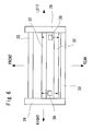
Fig. 1 , the automaticbanding packing machine 10 is provided with a packingmachine body 12 installed on a floor face of a plant, for example, and on an upper face of the packingmachine body 12, an upper-face table 16 constituting a work base for mounting an object to be packed for packing is formed. - That is, the packing
machine body 12 is formed in a box shape and contains a band (not shown) and the like inside, and thepacking machine body 12 has its upper face made as the upper-face table 16 on which the object to be packed is passed right and left inFig. 1 . - Also, in
Fig. 1 , lower parts offrames machine body 12. - Moreover, between an upper end of the right-
side front frame 18 and an upper end of the right-siderear frame 20, a right-side connection bar 26 is mounted. Similarly, between an upper end of the left-side front frame 22 and an upper end of a left-siderear frame 24, a left-side connection bar 28 is mounted, respectively. - Also, between a rear end of a right-
side connection bar 26 and a rear end of a left-side connection bar 28, arear connection bar 30 is mounted. - And between the right-
side connection bar 26 and the left-side connection bar 28, a horizontalband guide arch 32 is arranged above the upper-face table 16 so as to extend in a direction parallel with a passage direction of the object to be packed (right and left direction inFig. 1 ). - Also, between a longitudinal intermediate portion of the
rear connection bar 30 and a longitudinal intermediate portion of the horizontalband guide arch 32, as shown inFigs. 1 and2 , arectangular support plate 34 is mounted. - And above the upper-face table 16, in the direction parallel with the passage direction of the object to be packed, a pair of vertical
band guide arches - Also, the horizontal
band guide arch 32 is arranged above the verticalband guide arches - As shown in
Figs. 2 and4 , at thesupport plate 34, a left end side of a right-side rotating bar 40 is rotatably pin-connected, and at a right end side of the right-side rotating bar 40, an upper end of the right-side verticalband guide arch 36 is fixed. - Similarly, at the
support plate 34, a right end side of a left-side rotating bar 42 is rotatably pin-connected, and at a left end side of the left-side rotating bar 42, an upper end of the left-side verticalband guide arch 38 is fixed. - The right-side vertical
band guide arch 36 is suspended from the right-side rotating bar 40 and extends to the vicinity of the upper-face table 16 of the packingmachine body 12 through a slight gap. Similarly, the left-side verticalband guide arch 38 is suspended from the left-side rotating bar 42 and extends to the vicinity of the upper-face table 16 of the packingmachine body 12 through a slight gap. - By this arrangement, the vertical
band guide arches Fig. 1 ) (SeeFigs. 1 to 4 ). - As shown in
Figs. 2 and4 , on a lower face of thesupport plate 34, aslide plate 44 is provided slidably in the front and rear direction. Between theslide plate 44 and the right-side rotating bar 40, a right-side link 46 is mounted by pin-connection. Also, between theslide plate 44 and the left-side rotating bar 42, a left-side link 48 is mounted by pin-connection. - And on the lower face of the
support plate 34, acylinder device 50 constituting a driving mechanism is fixed, and a distal end portion of a piston of thiscylinder device 50 is fixed to theslide plate 44. - Therefore, in the automatic
banding packing machine 10, when the object to be packed is to be carried in / carried out, as shown inFig. 2 , it is only necessary to extend the piston of thecylinder device 50. That is, in this case, theslide plate 44 is slid rearward and at the same time, the right-side rotating bar 40 and the left-side rotating bar 42 are rotated in an arrow direction inFig. 2 . - As a result, the right-side vertical
band guide arch 36 integrated with the right-side rotating bar 40 is moved to the standby position retreated to a position close to the right-siderear frame 20, and the left-side verticalband guide arch 38 integrated with the left-side rotating bar 42 is moved to the standby position retreated to a position close to the left-siderear frame 24. - Therefore, in the automatic
banding packing machine 10, when the object to be packed is to be carried in / carried out, the verticalband guide arches - On the other hand, in the automatic
banding packing machine 10, in a state where the object to be packed has been carried in and located at a packing position, it is only necessary to contract the piston of thecylinder device 50. That is, in this case, theslide plate 44 is slid forward and the right-side rotating bar 40 and the left-side rotating bar 42 are rotated in an arrow direction inFig. 4 . - As a result, the right-side vertical
band guide arch 36 integrated with the right-side rotating bar 40 is moved to the communication position communicating with the horizontalband guide arch 32 and anarrow groove 52 formed on the upper-face table 16 of the packingmachine body 12. - Similarly, the left-side vertical
band guide arch 38 integrated with the left-side rotating bar 42 is moved to the communication position communicating with the horizontalband guide arch 32 and thenarrow groove 52 formed on the upper-face table 16 of the packingmachine body 12. - As a result, the pair of right-side vertical
band guide arch 36 and the left-side verticalband guide arch 38 and the horizontalband guide arch 32 form a U-shaped band guide arch, inside which a band passage is formed, and by feeding a band so as to have it pass through the band passage, band can be supplied surely into the band guide arch. - And in this state, a series of packing works including pulling-back of the band, fastening of the band, and moreover, welding performed substantially at the same time as cutting are all carried out automatically, whereby the object to be packed can be banded in parallel with the passage direction of the object to be packed.
- Between the
rear connection bar 30 and the horizontalband guide arch 32,reinforcement plates - In the above embodiment, the horizontal
band guide arch 32 is arranged in a fixed state above the upper-face table 16, but as shown by an arrow inFig. 5 , the horizontalband guide arch 32 may be constituted movably in the direction orthogonal to the passage direction of the object to be packed above the upper-face table 16. - With such configuration, by moving the horizontal
band guide arch 32 above the upper-face table 16 to an arbitrary position in the direction orthogonal to the passage direction of the object to be packed, by moving the pair of verticalband guide arches band guide arch 32 for performing banding, the object to be packed can be banded in parallel with the passage direction of the object to be packed at the arbitrary position in the direction orthogonal to the passage direction of the object to be packed. - Therefore, at plural positions in the direction orthogonal to the passage direction of the object to be packed, banding can be performed in parallel with the passage direction of the object to be packed, and firmer banding can be realized.
- Also, as shown in
Fig. 6 , the horizontalband guide arch 32 may be arranged in plural in the direction orthogonal to the passage direction of the object to be packed. - With such configuration, by moving the pair of vertical
band guide arches band guide arches 32 arranged in plural for performing banding, respectively, at arbitrary plural positions in the direction orthogonal to the passage direction of the object to be packed, the object to be packed can be banded in parallel with the passage direction of the object to be packed. - Therefore, at the plural positions in the direction orthogonal to the passage direction of the object to be packed, the object to be packed can be banded in parallel with the passage direction of the object to be packed, which enables firmer banding.
- Moreover, the above embodiment is configured so that the positions of the pair of vertical
band guide arches cylinder device 50 and the pair of verticalband guide arches cylinder device 50, but as shown inFigs. 7 and8 , it may be so configured that by employingstepping motors rotating bars rotating shafts motors band guide arches - By employing the stepping
motors band guide arches band guide arches -
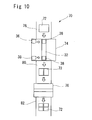
Fig. 9 is an outline plan view illustrating an embodiment of an automaticbanding packing system 70 using the automaticbanding packing machine 10 of the present invention. - As shown in
Fig. 9 , in the automaticbanding packing system 70, the two automatic banding packing machines are arranged adjacently so that the passage direction of an object to be packed 72 becomes a straight line. - That is, in the automatic
banding packing system 70 of this embodiment, a one automaticbanding packing machine 74 comprising the automaticbanding packing machine 10 of the present invention for banding on the object to be packed 72 in parallel with the passage direction of the object to be packed 72 is arranged on the downstream side. - Also, on the upstream side of the one automatic
banding packing machine 74, the other automaticbanding packing machine 76 with the configuration as described in the related art shown inFig. 12 for banding on the object to be packed 72 in the direction orthogonal to the passage direction of the object to be packed 72 of the one automaticbanding packing machine 74 is arranged. - And the object to be packed 72 is carried into the other automatic
banding packing machine 76 through a first conveyingline 78, and at the other automaticbanding packing machine 76, banding is performed on the object to be packed 72 in the direction orthogonal to the passage direction of the object to be packed 72 of the one automatic banding packing machine 74 (See the object to be packed 72 on a second conveyingline 80 inFig. 9 ) and carried into the one automaticbanding packing machine 74 through the second conveyingline 80. - The object to be packed 72 having been carried into the one automatic
banding packing machine 74 is banded in the cross state at the one automaticbanding packing machine 74 in parallel with the passage direction of the object to be packed 72 (See the object to be packed 72 on the third conveyingline 82 inFig. 9 ) and carried out through a third conveyingline 82. - Therefore, in the automatic
banding packing system 70 of this embodiment, the two automaticbanding packing machines line 78, the second conveyingline 80, and the third conveyingline 82. - In the automatic
banding packing system 70 configured as above, when the object to be packed 72 is to be packed in the cross state by a band, first, the object to be packed 72 is carried into the other automaticbanding packing machine 76 through the first conveyingline 78 and at the other automaticbanding packing machine 76, the object to be packed 72 is banded in the direction orthogonal to the passage direction of the object to be packed 72 of the one automatic banding packing machine 74 (right and left direction inFig. 9 ) (See the object to be packed 72 on the second conveyingline 80 inFig. 9 ). - Next, by extending the piston by driving the
cylinder device 50, the verticalband guide arches banding packing machine 74 are moved to the standby position in advance (position indicated by a dotted line inFig. 9 ). - And through the second conveying
line 80, the object to be packed 72 is carried into the one automaticbanding packing machine 74 and moved to the packing position (center position in the conveying direction of the automatic banding packing machine 74). - In this state, by contracting the piston by driving the
cylinder device 50, by moving the verticalband guide arches band guide arches Fig. 9 ) for performing banding in the cross state (See the object to be packed 72 on the third conveyingline 82 inFig. 9 ). - With such configuration, by the one automatic
banding packing machine 74, the object to be packed 72 can be banded in parallel with the passage direction of the object to be packed 72, and by the other automaticbanding packing machine 76, the object to be packed 72 can be banded in the direction orthogonal to the passage direction of the object to be packed 72 of the one automaticbanding packing machine 74 and bundled so that the object to be packed 72 can be banded in the cross state. - Moreover, even if the two automatic
banding packing machines - In this embodiment, the one automatic
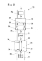
banding packing machine 74 for banding on the object to be packed 72 in parallel with the passage direction of the object to be packed 72 is arranged on the downstream side and the other automaticbanding packing machine 76 for banding on the object to be packed 72 in the direction orthogonal to the passage direction of the object to be packed 72 of the one automaticbanding packing machine 74 is arranged on the upstream side of the one automaticbanding packing machine 74 in the configuration as mentioned in the related art shown inFig. 12 , but the inverse configuration, that is, the one automaticbanding packing machine 74 may be arranged on the upstream side and the other automaticbanding packing machine 76 on the downstream side of the one automaticbanding packing machine 74 as shown inFig. 10 . - With such configuration, the one automatic
banding packing machine 74 for banding in parallel with the passage direction of the object to be packed and the other automaticbanding packing machine 76 for banding on the object to be packed 72 in the direction orthogonal to the passage direction of the object to be packed 72 of the one automaticbanding packing machine 74 can be freely arranged on the upstream side or the downstream side, and design freedom is improved. - Also, as shown in
Fig. 11 , the other automaticbanding packing machine 76 may be constituted by the automaticbanding packing machine 10 of the present invention. - In this case, as shown in
Fig. 11 , when the other automaticbanding packing machine 76 is constituted by the automaticbanding packing machine 10 of the present invention, the horizontalband guide arch 32 may be set to be arranged in parallel with the direction orthogonal to the passage direction of the obj ect to be packed 72 so that the front and rear direction inFig. 1 becomes the conveying direction of the object to be packed 72 in the automaticbanding packing machine 10. - With such configuration, by constituting not only the one automatic
banding packing machine 74 but also the other automaticbanding packing machine 76 by the automaticbanding packing machine 10 of the present invention, there is no need to perform the packing work by arranging the automatic banding packing machine with a different structure as before, and its control system does not become complicated and the control system itself is simplified. - The preferred embodiments of the present invention have been described above, but the present invention is not limited to them. For example, in the embodiment, the banding is performed on the object to be packed, but other than a band, other bundling members such as a banding state or chain state one can be used, for example. Moreover, in the above embodiment, the automatic banding packing system in which the automatic banding packing machine is arranged on a plane has been described, but the machine can be arranged not on a plane but in the vertical direction or three-dimensionally. As such, various changes are possible within a range not departing from the object of the present invention.
Claims (11)
- An automatic banding packing machine comprising:a packing machine body having an upper-face table on which an object to be packed passes;a pair of vertical band guide arches arranged above the upper-face table separately from each other in a direction parallel with a passage direction of the object to be packed; anda horizontal band guide arch arranged above the upper-face table in a direction parallel with the passage direction of the object to be packed,whereinthe pair of vertical band guide arches are constituted capable of moving their positions in a direction orthogonal to the passage direction of the object to be packed between a standby position separated from the horizontal band guide arch and a communication position communicating with the horizontal band guide arch.
- The automatic banding packing machine according to claim 1, wherein the horizontal band guide arch is arranged on an upper side from the vertical band guide arch.
- The automatic banding packing machine according to claim 1 or 2, wherein the horizontal band guide arch is arranged in a state fixed above the upper-face table.
- The automatic banding packing machine according to claim 1 or 2, wherein the horizontal band guide arch is constituted capable of moving its position in a direction orthogonal to the passage direction of the object to be packed above the upper-face table.
- The automatic banding packing machine according to any of claims 1 to 3, wherein the horizontal band guide arch is arranged in plural in a direction orthogonal to the passage direction of the object to be packed.
- The automatic banding packing machine according to any of claims 1 to 5, further comprising driving means for moving positions of the pair of vertical band guide arches in a direction orthogonal to the passage direction of the object to be packed, wherein
the driving means is constituted so as to move the positions of the pair of vertical band guide arches in the direction orthogonal to the passage direction of the object to be packed by extension of a cylinder through a link mechanism connected between a cylinder and the pair of vertical band guide arches. - The automatic banding packing machine according to any of claims 1 to 5, further comprising driving means for moving positions of the pair of vertical band guide arches in a direction orthogonal to the passage direction of the object to be packed, wherein
the driving means is constituted so as to move the positions of the pair of vertical band guide arches in the direction orthogonal to the passage direction of the object to be packed through a stepping motor. - An automatic banding packing system for performing banding in a cross state on an object to be packed, wherein
two automatic banding packing machines are arranged adjacently so that a passage direction of the object to be packed becomes a straight line;
one of the automatic banding packing machines is constituted by the automatic banding packing machine according to any of claims 1 to 7; and
the other automatic banding packing machine is constituted by an automatic banding packing machine for bundling the object to be packed in a direction orthogonal to the passage direction of the object to be packed of the one automatic banding packing machine. - The automatic banding packing system according to claim 8, wherein
the one automatic banding packing machine is disposed on the upstream side of a conveying line for conveying the object to be packed; and
the other automatic banding packing machine is disposed on the downstream side of the conveying line for conveying the object to be packed. - The automatic banding packing system according to claim 8, wherein
the one automatic banding packing machine is disposed on the downstream side of a conveying line for conveying the object to be packed; and
the other automatic banding packing machine is disposed on the upstream side of the conveying line for conveying the object to be packed. - The automatic banding packing system according to any of claims 8 to 10, wherein
the other automatic banding packing machine is constituted by the automatic banding packing machine according to any of claims 1 to 7.
Applications Claiming Priority (2)
| Application Number | Priority Date | Filing Date | Title |
|---|---|---|---|
| JP2007194588 | 2007-07-26 | ||
| PCT/JP2008/062455 WO2009014008A1 (en) | 2007-07-26 | 2008-07-10 | Automatic strapping packing machine and automatic strapping packing system |
Publications (2)
| Publication Number | Publication Date |
|---|---|
| EP2181925A1 true EP2181925A1 (en) | 2010-05-05 |
| EP2181925A4 EP2181925A4 (en) | 2013-08-28 |
Family
ID=40281266
Family Applications (1)
| Application Number | Title | Priority Date | Filing Date |
|---|---|---|---|
| EP08791025.3A Withdrawn EP2181925A4 (en) | 2007-07-26 | 2008-07-10 | AUTOMATIC LATCH PACKING MACHINE AND AUTOMATIC LOCK PACKAGING SYSTEM |
Country Status (10)
| Country | Link |
|---|---|
| US (1) | US8997641B2 (en) |
| EP (1) | EP2181925A4 (en) |
| JP (1) | JP5255563B2 (en) |
| KR (1) | KR101106085B1 (en) |
| CN (1) | CN101765543B (en) |
| BR (1) | BRPI0813979A2 (en) |
| CA (1) | CA2692901C (en) |
| RU (1) | RU2429170C1 (en) |
| TW (1) | TWI332467B (en) |
| WO (1) | WO2009014008A1 (en) |
Families Citing this family (11)
| Publication number | Priority date | Publication date | Assignee | Title |
|---|---|---|---|---|
| KR101307061B1 (en) * | 2011-11-15 | 2013-09-11 | (주)포스코엠텍 | Binding Apparatus |
| AU343832S (en) * | 2012-06-26 | 2012-08-10 | Adelaide Control Eng Pty Ltd | A containerised automated drum packing module |
| KR101838365B1 (en) * | 2013-06-20 | 2018-03-13 | 항저우 영썬 인텔리전트 이큅먼트 컴퍼니 리미티드 | Packaging machine core and cut belt warming and sticking method therefor |
| KR101464993B1 (en) * | 2014-05-02 | 2014-11-28 | 환 용 강 | Device for banding of waste vinyl |
| CN104071377B (en) * | 2014-06-10 | 2016-09-07 | 广州敏瑞汽车零部件有限公司 | Wheel cover baling press |
| USD837850S1 (en) * | 2016-05-18 | 2019-01-08 | Bobst Mex Sa | Packaging machine |
| USD837849S1 (en) * | 2016-05-18 | 2019-01-08 | Bobst Mex Sa | Packaging machine |
| USD839938S1 (en) * | 2016-05-18 | 2019-02-05 | Bobst Mex Sa | Packaging machine |
| US20230391481A1 (en) * | 2022-06-01 | 2023-12-07 | Taylor-Winfield Technologies, Inc. | Robotic strapping machine with pivoting strapping head and method |
| CN115557036B (en) * | 2022-10-10 | 2025-05-30 | 兰科智能工程(广东)有限公司 | An intelligent strapping system |
| CN115892564B (en) * | 2022-11-29 | 2025-11-04 | 连智(大连)智能科技有限公司 | A horizontal tape-laying device for photovoltaic module tooling position |
Family Cites Families (18)
| Publication number | Priority date | Publication date | Assignee | Title |
|---|---|---|---|---|
| DE3303956C2 (en) | 1983-02-05 | 1987-08-20 | Berthold 7902 Blaubeuren Bührle | Device for strapping cuboid packaged goods |
| JPS61127410A (en) * | 1984-11-14 | 1986-06-14 | 中野エンジニアリング株式会社 | Crossed winding method of material to be packaged |
| SU1421621A1 (en) * | 1985-09-24 | 1988-09-07 | Ульяновский научно-исследовательский и проектно-технологический институт машиностроения | Apparatus for tying up a stack of articles |
| US5078057A (en) * | 1990-01-05 | 1992-01-07 | Illinois Tool Works Inc. | Binding machine, such as strapping machine |
| JPH05112315A (en) * | 1991-10-11 | 1993-05-07 | Sutorapatsuku Kk | Packing equipment |
| US5379687A (en) * | 1994-02-04 | 1995-01-10 | Continental Eagle Corporation | Bale wire tie apparatus and method |
| DE19615009B4 (en) | 1996-04-16 | 2005-09-29 | Smb Schwede Maschinenbau Gmbh | Stacker with strapping device |
| CN2374454Y (en) * | 1999-04-16 | 2000-04-19 | 怡进工业股份有限公司 | Improved tieing band guide rack of bander |
| DE19920531C2 (en) * | 1999-05-05 | 2003-12-04 | Smb Schwede Maschb Gmbh | Packaging line for magazines, magazines and the like printed products |
| DE10010275A1 (en) | 2000-03-02 | 2001-09-13 | Schneider & Ozga | Hoop-strapping for packaged goods comprises conveyor, guide, lengthwise duct section with entry and outlet, and two vertical guide duct sections |
| DE10111395A1 (en) | 2001-03-09 | 2002-09-19 | Helmut Schmetzer | Device for the longitudinal strapping of an object with a strapping |
| EP1279597B1 (en) * | 2001-07-28 | 2004-10-06 | Schneider + Ozga | Strapping apparatus |
| JP3971927B2 (en) | 2002-01-09 | 2007-09-05 | ストラパック株式会社 | Packing equipment |
| US6951170B2 (en) * | 2003-06-17 | 2005-10-04 | Illinois Tool Works, Inc. | Strapping machine with improved chute release system |
| CN2682001Y (en) * | 2003-10-30 | 2005-03-02 | 许春虎 | Automatic rod bundling machine |
| DE10357829A1 (en) * | 2003-12-09 | 2005-07-28 | Signode Bernpak Gmbh | Apparatus for longitudinally gripping a package, in particular a stack of newspapers, magazines or the like. |
| JP2006290431A (en) * | 2005-04-13 | 2006-10-26 | Strapack Corp | Automatic banding packing machine |
| JP2006315746A (en) | 2005-05-16 | 2006-11-24 | Strapack Corp | Automatic banding packing machine |
-
2008
- 2008-07-10 JP JP2009524444A patent/JP5255563B2/en not_active Expired - Fee Related
- 2008-07-10 WO PCT/JP2008/062455 patent/WO2009014008A1/en not_active Ceased
- 2008-07-10 KR KR1020097027293A patent/KR101106085B1/en not_active Expired - Fee Related
- 2008-07-10 RU RU2010102843/11A patent/RU2429170C1/en active
- 2008-07-10 CN CN200880100452XA patent/CN101765543B/en active Active
- 2008-07-10 BR BRPI0813979-2A2A patent/BRPI0813979A2/en not_active Application Discontinuation
- 2008-07-10 CA CA2692901A patent/CA2692901C/en active Active
- 2008-07-10 US US12/670,021 patent/US8997641B2/en active Active
- 2008-07-10 EP EP08791025.3A patent/EP2181925A4/en not_active Withdrawn
- 2008-07-18 TW TW097127272A patent/TWI332467B/en not_active IP Right Cessation
Also Published As
| Publication number | Publication date |
|---|---|
| KR101106085B1 (en) | 2012-01-18 |
| RU2429170C1 (en) | 2011-09-20 |
| CA2692901A1 (en) | 2009-01-29 |
| TW200906675A (en) | 2009-02-16 |
| JP5255563B2 (en) | 2013-08-07 |
| KR20100017950A (en) | 2010-02-16 |
| TWI332467B (en) | 2010-11-01 |
| JPWO2009014008A1 (en) | 2010-09-30 |
| BRPI0813979A2 (en) | 2015-01-06 |
| WO2009014008A1 (en) | 2009-01-29 |
| CA2692901C (en) | 2012-12-11 |
| US20100205914A1 (en) | 2010-08-19 |
| CN101765543B (en) | 2011-12-14 |
| EP2181925A4 (en) | 2013-08-28 |
| CN101765543A (en) | 2010-06-30 |
| US8997641B2 (en) | 2015-04-07 |
Similar Documents
| Publication | Publication Date | Title |
|---|---|---|
| US8997641B2 (en) | Automatic banding packing machine and automatic banding packing system | |
| US8607695B2 (en) | Strap driving device for a strapping machine | |
| CN103863600B (en) | Hot forming packer and method | |
| KR101950986B1 (en) | Packing apparatus of box multi banding | |
| CN103118947B (en) | Strapping units for packaging machines | |
| US7168910B2 (en) | Device for transporting a horizontal stack positioned on a support and formed in a gathering machine with upright, lined-up signatures | |
| US6470655B1 (en) | Packaging line for periodicals, magazines and similar printed products | |
| EP1810924B1 (en) | Integrated package pacer for strapping machine | |
| JP4844989B2 (en) | Supply device for horizontal bag making and filling machine and control method thereof | |
| JP5229659B2 (en) | Sheet feeding apparatus and sheet packaging machine using the same | |
| KR100961408B1 (en) | Tie machine of roll wrapper | |
| AU2002326212B2 (en) | Method and device for strapping one or more packets with a band with label means | |
| JP2005001768A (en) | Packing machine | |
| IT9022576A1 (en) | EQUIPMENT FOR THE FORMATION OF PACKS OF BOXES PRODUCED BY BENDING-GLUING MACHINES OR SEWING MACHINES PACKED WITH STRAP | |
| US8707863B2 (en) | Strapping machine and method of operating same | |
| CN216834501U (en) | Continuous type carton tilting mechanism and cartoning equipment | |
| JP4619869B2 (en) | Feeding device for horizontal bag making and filling machine | |
| JP5377896B2 (en) | Rebar processing equipment | |
| JP3662397B2 (en) | Conveying device for integrated packaging of packaging sheets | |
| KR101561056B1 (en) | Turning Arm Type Wrapping Device | |
| CN101218160B (en) | Sheet stacking device | |
| US7757458B2 (en) | Packaging machine equipped with independent cutting and welding bars | |
| KR930007945B1 (en) | Device for banding boxes | |
| WO2026048841A1 (en) | Resin sealing apparatus | |
| JP2010005661A (en) | Reinforcing bar machining device |
Legal Events
| Date | Code | Title | Description |
|---|---|---|---|
| PUAI | Public reference made under article 153(3) epc to a published international application that has entered the european phase |
Free format text: ORIGINAL CODE: 0009012 |
|
| 17P | Request for examination filed |
Effective date: 20091230 |
|
| AK | Designated contracting states |
Kind code of ref document: A1 Designated state(s): AT BE BG CH CY CZ DE DK EE ES FI FR GB GR HR HU IE IS IT LI LT LU LV MC MT NL NO PL PT RO SE SI SK TR |
|
| AX | Request for extension of the european patent |
Extension state: AL BA MK RS |
|
| DAX | Request for extension of the european patent (deleted) | ||
| A4 | Supplementary search report drawn up and despatched |
Effective date: 20130731 |
|
| RIC1 | Information provided on ipc code assigned before grant |
Ipc: B65B 13/14 20060101AFI20130725BHEP Ipc: B65B 13/18 20060101ALI20130725BHEP Ipc: B65B 27/08 20060101ALI20130725BHEP |
|
| STAA | Information on the status of an ep patent application or granted ep patent |
Free format text: STATUS: THE APPLICATION IS DEEMED TO BE WITHDRAWN |
|
| 18D | Application deemed to be withdrawn |
Effective date: 20140301 |