EP2181926A2 - Zentriervorrichtung und Flaschenverpackungsmaschine - Google Patents
Zentriervorrichtung und Flaschenverpackungsmaschine Download PDFInfo
- Publication number
- EP2181926A2 EP2181926A2 EP09172791A EP09172791A EP2181926A2 EP 2181926 A2 EP2181926 A2 EP 2181926A2 EP 09172791 A EP09172791 A EP 09172791A EP 09172791 A EP09172791 A EP 09172791A EP 2181926 A2 EP2181926 A2 EP 2181926A2
- Authority
- EP
- European Patent Office
- Prior art keywords
- bottles
- longitudinal wall
- predisposed
- cellular structure
- longitudinal
- Prior art date
- Legal status (The legal status is an assumption and is not a legal conclusion. Google has not performed a legal analysis and makes no representation as to the accuracy of the status listed.)
- Granted
Links
Images


Classifications
-
- B—PERFORMING OPERATIONS; TRANSPORTING
- B65—CONVEYING; PACKING; STORING; HANDLING THIN OR FILAMENTARY MATERIAL
- B65B—MACHINES, APPARATUS OR DEVICES FOR, OR METHODS OF, PACKAGING ARTICLES OR MATERIALS; UNPACKING
- B65B21/00—Packaging or unpacking of bottles
- B65B21/02—Packaging or unpacking of bottles in or from preformed containers, e.g. crates
- B65B21/025—Packaging or unpacking of bottles in or from preformed containers, e.g. crates the bottles being arranged in a head-to-bottom formation
-
- B—PERFORMING OPERATIONS; TRANSPORTING
- B65—CONVEYING; PACKING; STORING; HANDLING THIN OR FILAMENTARY MATERIAL
- B65B—MACHINES, APPARATUS OR DEVICES FOR, OR METHODS OF, PACKAGING ARTICLES OR MATERIALS; UNPACKING
- B65B21/00—Packaging or unpacking of bottles
- B65B21/02—Packaging or unpacking of bottles in or from preformed containers, e.g. crates
- B65B21/14—Introducing or removing groups of bottles, for filling or emptying containers in one operation
- B65B21/18—Introducing or removing groups of bottles, for filling or emptying containers in one operation using grippers engaging bottles, e.g. bottle necks
-
- B—PERFORMING OPERATIONS; TRANSPORTING
- B65—CONVEYING; PACKING; STORING; HANDLING THIN OR FILAMENTARY MATERIAL
- B65B—MACHINES, APPARATUS OR DEVICES FOR, OR METHODS OF, PACKAGING ARTICLES OR MATERIALS; UNPACKING
- B65B39/00—Nozzles, funnels or guides for introducing articles or materials into containers or wrappers
- B65B39/006—Grids for introducing bottles into cases
Definitions
- the invention relates to a centring device for packing bottles and to a bottle-packing machine.
- Machines for packing bottles generally comprise a movement device predisposed to collect and deposit a determined number of bottles internally of cardboard boxes.
- the bottles are generally removed from the movement device in an ordered matrix arrangement which contains a certain number of groups of bottles. Each group of bottles is destined to be inserted and contained in a single box.
- bottles such as for example sparkling wine or champagne, exhibit a cylindrical bottom portion which extends in height over a more-or-less equivalent tract to the neck portion.
- these bottles are normally stacked alternatively topside up and upside down in the box, i.e. such that an upright bottle is next to an over-turned bottle.
- This means that the cylindrical bottom portion of a bottle is next to the neck portion of an adjacent bottle, such that the space taken up is about the sum of the diameter of the space occupied by the bottom portion and the diameter of the neck portion. If the two bottles were placed side-by-side and both upright, the overall diameter would be about twice the diameter of the bottom portion.
- the most widely-used packing boxes for this type of bottle contain six bottles, arranged in two rows of three bottles, in which the bottles at the end are straight and the intermediate bottles are over-turned.
- a cellular structure is interposed, made up of at least a larger wall, predisposed to separate the two rows of three bottles, and at least two smaller walls, predisposed to separate the bottles of each row.
- Correct positioning of the bottles internally of the boxes means that each bottle unerringly enters the cell provided therefor. This is obtained by interposing a centring device between the boxes and the movement device, which centring device comprises a cellular structure that defines a plurality of openings predisposed to enable passage of the bottles. The openings of the cellular structure are aligned with the container boxes of the bottles such that when the movement device descends the bottles each enter the right cell, with no error.
- the known centring devices have a predetermined structure in which the cellular structure defines openings of a fixed shape and extension. This necessarily means that the upright bottles and the over-turned bottles have to be introduced into the boxes in two distinct stations, each of which exhibits a centring device suitable for passage of the upright bottles or the overturned bottles. Thus it is necessary to provide two movement devices and two centring devices if packing times are to be kept to a minimum.
- the aim of the present invention is to provide a centring device and a bottle-packing machine which enables contemporaneous introduction of upright and overturned bottles internally of a box.
- the invention enables a considerable reduction of the times required for packing a carton with bottles without substantially increasing the costs of the apparatus required.
- the centring device of the present invention is particularly applicable for use in a machine for packing bottles which comprises a movement device 12, predisposed for moving a certain number of bottles 51, 52 along at least a vertical direction.
- a determined number of cardboard boxes 60 is arranged below the movement device 12, predisposed to receive the bottles 51, 52 positioned upright and overturned in a determined pattern.
- the movement device 12 is brought into a vertically-aligned position with regard to the boxes 60 and descends until it deposits the bottles 51, 52 internally of the boxes 60.
- the centring device 1 is arranged in an intermediate position between the movement device 12 and the container boxes 60 for the bottles, and its function is to correctly direct the bottles into the boxes 60.
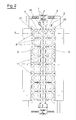
- the centring device of the present invention comprises a cellular structure 2 ( figure 2 ) which defines a plurality of openings 21, 22, 23 predisposed to enable passage of bottles 51, 52.
- the cellular structure 2 substantially has the function of being a centring template for directly correctly the bottles 51, 52 during the descent thereof towards the packing boxes 60.
- Regulating means 3 are predisposed to cause a variation in the size and/or conformation of the openings 21, 22, 23 during passage of the bottles 51, 52, such that each opening 21, 22, 23 enables progressive passage of consecutive sections of a bottle 51, 52. Thanks to this possibility, the openings 21, 22, 23 can open or close progressively to enable passage of the various sections of the bottles.
- the cellular structure 2 comprises at least a first longitudinal wall 4 which separates at least a first and a second opening 21, 22 from one another and which can slide along a transversal direction X, such as to vary the size of the first and the second openings 21, 22 between a maximum extension configuration and a minimum extension configuration.
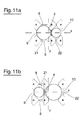
- This embodiment of the invention enables centring a pair of bottles 51, 52 of which a first is upright and the other is overturned. Consider for example two bottles 51, 52 adjacent to one another which are translated to pass through two contiguous openings 21, 22.
- the upright bottle 51 offers the bottom portion to the cellular structure 2, the section of which is greater than the neck section, while the overturned bottle 52 offers the neck portion towards the cellular structure 2.
- a first opening 21 is in a maximum extension configuration in order to enable passage of the bottom portion of the upright bottle 51, while the second opening 52 is in a minimum extension configuration, which enables passage of the neck portion of the overturned bottle 52.
- the regulating means 3 contemporaneously vary the conformation and the size of the openings 21, 22 such that the first opening 21 reduces in size in order to follow the reduction of the section of the upright bottle 51 which transits from the bottom portion to the neck portion, while the second opening 22 increases in size in order to follow the increase of the section of the overturned bottle 52 which transits from the neck portion to the bottom portion. If it is not possible to vary the size of the two openings 21, 22 during the passage of the bottles 51, 52, the bottles would not be able to transit contemporaneously through the openings 21, 22.
- the regulating means 3 are predisposed to cause the sliding of the first longitudinal wall 4.
- the minimum embodiment of the embodiment can be repeated several times either in a longitudinal direction Y and in a transversal direction such as to enable contemporaneous centring of several pairs of bottles 51, 52, both upright and overturned. For example, by repeating this embodiment once in a longitudinal direction Y it is possible to centre four bottles, of which two are upright and two overturned. By repeating the minimum structure four more times in a longitudinal direction Y, twelve bottles can be centred, arranged on two rows of six bottles, a row of upright bottles and a row of overturned bottles. In this way it is possible to pack a box of twelve bottles with a single operation.
- the cell structure 2 comprises a second longitudinal wall 5, arranged parallel to the first longitudinal wall 4 which separates the second opening 22 from a third opening 23 and which can slide along the transversal direction X.
- the invention enables centring of three aligned bottles, of which the two end bottles are in an upright position and the intermediate bottle is overturned, or vice versa.
- the regulating means 3 are predisposed to determine a relative sliding between the first and the second longitudinal wall 4, 5 such as to vary the size of the first, second and third openings 21, 22, 23, between a maximum extension configuration and a minimum extension configuration.
- the first and the second longitudinal walls 4, 5 are initially in a position in which they are separated by a minimum distance, such that the intermediate opening 22 is in a minimum extension configuration in order to allow passage of the neck section of the overturned bottle, while the two end openings 21, 23 are in a maximum extension configuration in order to enable passage of the bottom section of the two upright bottles.
- the regulating means 3 distance the first and the second longitudinal walls from one another such that the two end openings 21, 23 reduce is size in order to follow the reducing of the section of the upright bottles 51 transiting from the bottom portion to the neck portions, while the intermediate opening 22 increases in size to follow the increase in section of the overturned bottle 52 transiting from the neck portion to the bottom portion.
- This more complex embodiment of the invention can also be repeated several times, both in the longitudinal direction, as demonstrated in the figures, and in the transversal direction, such as to enable centring of a greater number of sets of three bottles.
- the packing of a twelve-bottle box can be obtained for example by repeating the centring device three times for sets of three bottles, obtaining a device which enables centring of twelve bottles arranged on three rows of four bottles in which a first row is of upright bottles and a second row is of overturned bottles.
- This device could therefore be repeated once in the transversal direction X such as to obtain overall a device which enables centring of twelve bottles, arranged in four rows of three bottles each, two rows of upright bottles alternated with two rows of overturned bottles.
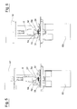
- the regulating means 3 comprise a cam 6 (figures from 3 to 10).
- the cam 6 is predisposed to push the first longitudinal wall 4 to slide at least in an outward direction.
- Elastic means 7, for example one or more helical springs, are predisposed to maintain the first longitudinal wall 4 in contact with the cam 6 and to push the longitudinal wall to slide in an opposite, return direction.
- a desmodromic, or positive, command in which the cam 6 actively determines both slidings of the longitudinal wall 4, the presence of elastic means no longer being necessary.
- the cam 6 is predisposed to wedge between the first and the second longitudinal wall 4, 5 such as to distance them from one another.
- the cam 6 is in the form of an elongate body provided with a tapered end portion 6a.
- the longitudinal walls 4, 5 are provided with shaped appendages 4a, 5a which project at an end of the walls are divergent upwardly such as to define an entrance for the cam 6.
- the elastic means 7 are predisposed to maintain the first and the second longitudinal walls 4, 5 in contact with the cam 6 and to push the first and the second longitudinal wall 4, 5 towards one another. The presence of the elastic means 7 can be omitted if the cam 6 command is desmodromic.
- the centring device of the invention can be structured such as to enable the centring of a desired number of bottles.
- the device is structured such as to enable centring of twenty four bottles arranged in three rows of which the two ends are upright bottles 51, while the intermediate row is made up of upturned bottles.
- the number of sets of three bottles which in the illustrated case is eight, can be increased or reduced according to needs.
- the device could be structured for centring of a determined number of pairs of longitudinally-aligned bottles. In this case only the first longitudinal wall 4 would be necessary.
- Figures 13 and 14 show two possible embodiments of the centring device suitable for centring twelve bottles.
- the cellular structure 2 comprises a plurality of transversal walls 8 ( figure 2 ) arranged perpendicular to the first longitudinal wall 4 and separated by a certain distance.
- the cellular structure further comprises two external longitudinal walls 9, 10, parallel to the first longitudinal wall 4, between which the first and the second longitudinal wall 4, 5 are positioned.
- the various walls delimit a plurality of openings 21, 22, 23 the size of which is modified by the displacing of the first longitudinal wall 4, in the embodiment for pairs of bottles, or by displacement of the first and the second longitudinal wall 4, 5 in the embodiment for sets of three bottles.
- the longitudinal walls 4, 5, 9, 10 and the transversal walls 8 intersect at nodes where conical elements 11 are positioned which are predisposed to facilitate entry of the bottles 51, 52 into the openings 21, 22, 23.
- Figure 1 shows a schematic view of a bottle-packing machine comprising a centring device 1 of the present invention.
- the machine comprises a movement device 12, predisposed for moving ordered groups of bottles 51, 52 in which the bottles are aligned in at least a first longitudinal row of upright bottles 51, a second longitudinal row of overturned bottles 52 and a third row of upright bottles 51.
- a centring device 1 of the present invention is arranged below the movement device 12.
- the movement device 12 in a collecting station which is not illustrated, collects an ordered group of bottles 51, 52 with gripping means 12a, 12b and moves into a position in which the openings 21, 22, 23 of the cellular structure 2 are aligned along a vertical direction with the gripping means 12a, 12b.
- the movement device 12 is mobile vertically between an upper position, in which it is at a greater distance from the centring device 1 and the bottles 51, 52 are above the cellular structure 2, and a lower position, in which it is at a smaller distance from the centring device 1 and the bottles 51, 52 are below the cellular structure 2.
- the bottles 51, 52 transit through the openings 21, 22, 23 which, by effect of the regulating means 3, vary their size and/or their conformation such as to enable progressive passage of consecutive sections of the bottles 51, 52.
- the cam 6 is preferably associated to the movement device 12 (figures from 3 to 10) such that, at a certain point in the descent of the movement device 12, the cam 6 enters into contact with the shaped appendages 4a, 5a of the first and the second longitudinal wall 4, 5 causing the reciprocal distancing thereof along the transversal direction X.
- the cam 6 is arranged, with respect to the gripping means 12a, 12b, such as to enter into contact with the appendages 4a, 5a in order to cause distancing of the first and the second longitudinal walls 4, 5 in the moment at which the transit of the neck sections of the overturned bottles through the cellular structure 2 has terminated and the transit of the larger section has begun.
- Figure 5 shows the moment at which the transit of the neck portion of the overturned bottles 52 terminates.
- the cam 6 is shaped such that the first and the second longitudinal section 4, 5 progressively distance from one another as the overturned bottles 52 proceed downwards, increasing the size of the section transiting through the cellular structure 2.
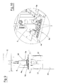
- Figure 8 shows the moment when the transit of the cylindrical bottom portion of the overturned bottles 52 begins and the cam 6 pushes the first and the second longitudinal wall 4, 5 to the maximum reciprocal distance. In this way, the change in size of the openings 21, 22, 23 of the cellular structure is perfectly synchronised with the descending movement of the movement device 12.
- the boxes 60 for containing the bottles are successively positioned below the centring device, in this case four boxes each for containing six bottles.
- a mobile conveyor plane (not illustrated) can be predisposed, which supplies the boxes 60 to below the centring device 1, and, following the depositing of the bottles, distances them towards the successive work stations.
- the centring device offers important advantages.
- the centring device enables the upright and the overturned bottles to be introduced contemporaneously into the container boxes. With respect to the centring devices at present available on the market, which allow only separate introduction of the upright and overturned bottles, this enables bottle-packing times to be reduced by half. Further, the greater productivity of the machine using the centring device does not lead to an especially relevant increase in costs.
Landscapes
- Engineering & Computer Science (AREA)
- Mechanical Engineering (AREA)
- Wrapping Of Specific Fragile Articles (AREA)
- Auxiliary Devices For And Details Of Packaging Control (AREA)
Applications Claiming Priority (1)
| Application Number | Priority Date | Filing Date | Title |
|---|---|---|---|
| ITMO2008A000279A IT1391601B1 (it) | 2008-10-31 | 2008-10-31 | Dispositivo di centraggio e macchina per il confezionamento di bottiglie. |
Publications (3)
| Publication Number | Publication Date |
|---|---|
| EP2181926A2 true EP2181926A2 (de) | 2010-05-05 |
| EP2181926A3 EP2181926A3 (de) | 2010-06-09 |
| EP2181926B1 EP2181926B1 (de) | 2010-12-22 |
Family
ID=41719389
Family Applications (1)
| Application Number | Title | Priority Date | Filing Date |
|---|---|---|---|
| EP09172791A Active EP2181926B1 (de) | 2008-10-31 | 2009-10-12 | Zentriervorrichtung und Flaschenverpackungsmaschine |
Country Status (5)
| Country | Link |
|---|---|
| EP (1) | EP2181926B1 (de) |
| AT (1) | ATE492475T1 (de) |
| DE (1) | DE602009000466D1 (de) |
| ES (1) | ES2354772T3 (de) |
| IT (1) | IT1391601B1 (de) |
Cited By (1)
| Publication number | Priority date | Publication date | Assignee | Title |
|---|---|---|---|---|
| EP3421381A1 (de) * | 2017-05-02 | 2019-01-02 | Seidenader Maschinenbau GmbH | Zentriervorrichtung |
Families Citing this family (1)
| Publication number | Priority date | Publication date | Assignee | Title |
|---|---|---|---|---|
| DE102015106759B4 (de) | 2015-04-30 | 2018-12-13 | Khs Gmbh | Packvorrichtung zum Verpacken von Behältern in eine Verpackungseinheit mit einem Gefache |
Family Cites Families (5)
| Publication number | Priority date | Publication date | Assignee | Title |
|---|---|---|---|---|
| DE1231613B (de) * | 1963-07-13 | 1966-12-29 | Schickedanz Ver Papierwerk | Verfahren zum automatischen Verpacken von Flaschen |
| US3694993A (en) * | 1970-05-20 | 1972-10-03 | Simplimatic Eng Co | Automatic bottle packing method and apparatus |
| FR2500806A1 (fr) * | 1981-02-27 | 1982-09-03 | Jourdain Andre | Dispositif de retournement et prehension de bouteilles pour la mise en cartons |
| US6729103B1 (en) * | 1994-11-10 | 2004-05-04 | Hartness International, Inc. | Continuous circular motion case packing and depacking apparatus and method |
| DE29708319U1 (de) * | 1997-05-09 | 1998-09-10 | Certus Maschinenbau GmbH, 86316 Friedberg | Zentrierrahmen für Packmaschinen |
-
2008
- 2008-10-31 IT ITMO2008A000279A patent/IT1391601B1/it active
-
2009
- 2009-10-12 AT AT09172791T patent/ATE492475T1/de not_active IP Right Cessation
- 2009-10-12 DE DE602009000466T patent/DE602009000466D1/de active Active
- 2009-10-12 EP EP09172791A patent/EP2181926B1/de active Active
- 2009-10-12 ES ES09172791T patent/ES2354772T3/es active Active
Cited By (1)
| Publication number | Priority date | Publication date | Assignee | Title |
|---|---|---|---|---|
| EP3421381A1 (de) * | 2017-05-02 | 2019-01-02 | Seidenader Maschinenbau GmbH | Zentriervorrichtung |
Also Published As
| Publication number | Publication date |
|---|---|
| IT1391601B1 (it) | 2012-01-11 |
| EP2181926A3 (de) | 2010-06-09 |
| EP2181926B1 (de) | 2010-12-22 |
| ES2354772T3 (es) | 2011-03-17 |
| ATE492475T1 (de) | 2011-01-15 |
| DE602009000466D1 (de) | 2011-02-03 |
| ITMO20080279A1 (it) | 2010-05-01 |
Similar Documents
| Publication | Publication Date | Title |
|---|---|---|
| US10486914B2 (en) | Device and method for forming batches | |
| US10604291B2 (en) | Apparatus and method for handling articles | |
| US9126768B2 (en) | Conveyor for forming at least one batch of products | |
| EP0242017A1 (de) | Verfahren und Gerät zum Gruppieren von Gegenständen | |
| US3653178A (en) | Apparatus for charging trays having a surrounding flange with articles ordered in groups | |
| US11753208B2 (en) | Method for transporting spacers for cigarette packs | |
| RU2010143981A (ru) | Способ и устройство для обработки пачек ценных бумаг, в частности пачек банкнот | |
| ITBO20100286A1 (it) | Dispositivo di tappatura | |
| EP2030909A1 (de) | Stütz- und Lagerplatte für Behälter | |
| EP2181926B1 (de) | Zentriervorrichtung und Flaschenverpackungsmaschine | |
| US20170043890A1 (en) | Apparatus and method for loading articles into a packing case | |
| US20160016689A1 (en) | Low depth crate | |
| CN100371220C (zh) | 用来制造香烟组的装置 | |
| RU2008114324A (ru) | Способ и устройство автоматизированной упорядоченной укладки пластиковых заготовок в картонные коробки | |
| IT202000007087A1 (it) | Magazzino per mazzette di sbozzati | |
| JP6521292B2 (ja) | ケースパッカ及びケースパッカの制御方法 | |
| KR101799616B1 (ko) | 카드보드 시트로 만들어진 블랭크, 교차 브레이싱 인서트, 이러한 블랭크로부터 교차 브레이싱 인서트를 제조하는 방법 및 기계 | |
| EP3849909B1 (de) | Verfahren und system zur anordnung von artikeln | |
| US20160332758A1 (en) | Centering devices for carrier packers | |
| US20250289602A1 (en) | Packaging apparatus and method for applying packaging to an article combination | |
| CN101677626A (zh) | 用于填装竖盒排架的填装仓以及具有这种填装仓的填装站 | |
| GB2202509A (en) | Applying a top carrier carton onto tops of groups of bottles | |
| EP2500284B1 (de) | Maschine zum Bilden und Verschachteln von Zigarettengruppen | |
| EP3093243B1 (de) | Zentriervorrichtungen für trägerpacker | |
| ES2384145B1 (es) | Máquina paletizadora de botellas. |
Legal Events
| Date | Code | Title | Description |
|---|---|---|---|
| PUAI | Public reference made under article 153(3) epc to a published international application that has entered the european phase |
Free format text: ORIGINAL CODE: 0009012 |
|
| AK | Designated contracting states |
Kind code of ref document: A2 Designated state(s): AT BE BG CH CY CZ DE DK EE ES FI FR GB GR HR HU IE IS IT LI LT LU LV MC MK MT NL NO PL PT RO SE SI SK SM TR |
|
| AX | Request for extension of the european patent |
Extension state: AL BA RS |
|
| PUAL | Search report despatched |
Free format text: ORIGINAL CODE: 0009013 |
|
| AK | Designated contracting states |
Kind code of ref document: A3 Designated state(s): AT BE BG CH CY CZ DE DK EE ES FI FR GB GR HR HU IE IS IT LI LT LU LV MC MK MT NL NO PL PT RO SE SI SK SM TR |
|
| AX | Request for extension of the european patent |
Extension state: AL BA RS |
|
| RIC1 | Information provided on ipc code assigned before grant |
Ipc: B65B 39/00 20060101AFI20100503BHEP |
|
| 17P | Request for examination filed |
Effective date: 20100722 |
|
| GRAP | Despatch of communication of intention to grant a patent |
Free format text: ORIGINAL CODE: EPIDOSNIGR1 |
|
| RIC1 | Information provided on ipc code assigned before grant |
Ipc: B65B 39/00 20060101AFI20100830BHEP |
|
| RIN1 | Information on inventor provided before grant (corrected) |
Inventor name: SAIN, MARINO |
|
| GRAS | Grant fee paid |
Free format text: ORIGINAL CODE: EPIDOSNIGR3 |
|
| GRAA | (expected) grant |
Free format text: ORIGINAL CODE: 0009210 |
|
| AK | Designated contracting states |
Kind code of ref document: B1 Designated state(s): AT BE BG CH CY CZ DE DK EE ES FI FR GB GR HR HU IE IS IT LI LT LU LV MC MK MT NL NO PL PT RO SE SI SK SM TR |
|
| AX | Request for extension of the european patent |
Extension state: RS |
|
| REG | Reference to a national code |
Ref country code: GB Ref legal event code: FG4D |
|
| REG | Reference to a national code |
Ref country code: CH Ref legal event code: EP |
|
| REG | Reference to a national code |
Ref country code: IE Ref legal event code: FG4D |
|
| REF | Corresponds to: |
Ref document number: 602009000466 Country of ref document: DE Date of ref document: 20110203 Kind code of ref document: P |
|
| REG | Reference to a national code |
Ref country code: DE Ref legal event code: R096 Ref document number: 602009000466 Country of ref document: DE Effective date: 20110203 |
|
| REG | Reference to a national code |
Ref country code: ES Ref legal event code: FG2A Effective date: 20110307 |
|
| REG | Reference to a national code |
Ref country code: NL Ref legal event code: VDEP Effective date: 20101222 |
|
| PG25 | Lapsed in a contracting state [announced via postgrant information from national office to epo] |
Ref country code: LT Free format text: LAPSE BECAUSE OF FAILURE TO SUBMIT A TRANSLATION OF THE DESCRIPTION OR TO PAY THE FEE WITHIN THE PRESCRIBED TIME-LIMIT Effective date: 20101222 |
|
| LTIE | Lt: invalidation of european patent or patent extension |
Effective date: 20101222 |
|
| PG25 | Lapsed in a contracting state [announced via postgrant information from national office to epo] |
Ref country code: AT Free format text: LAPSE BECAUSE OF FAILURE TO SUBMIT A TRANSLATION OF THE DESCRIPTION OR TO PAY THE FEE WITHIN THE PRESCRIBED TIME-LIMIT Effective date: 20101222 Ref country code: SE Free format text: LAPSE BECAUSE OF FAILURE TO SUBMIT A TRANSLATION OF THE DESCRIPTION OR TO PAY THE FEE WITHIN THE PRESCRIBED TIME-LIMIT Effective date: 20101222 Ref country code: HR Free format text: LAPSE BECAUSE OF FAILURE TO SUBMIT A TRANSLATION OF THE DESCRIPTION OR TO PAY THE FEE WITHIN THE PRESCRIBED TIME-LIMIT Effective date: 20101222 Ref country code: BG Free format text: LAPSE BECAUSE OF FAILURE TO SUBMIT A TRANSLATION OF THE DESCRIPTION OR TO PAY THE FEE WITHIN THE PRESCRIBED TIME-LIMIT Effective date: 20110322 Ref country code: FI Free format text: LAPSE BECAUSE OF FAILURE TO SUBMIT A TRANSLATION OF THE DESCRIPTION OR TO PAY THE FEE WITHIN THE PRESCRIBED TIME-LIMIT Effective date: 20101222 Ref country code: SI Free format text: LAPSE BECAUSE OF FAILURE TO SUBMIT A TRANSLATION OF THE DESCRIPTION OR TO PAY THE FEE WITHIN THE PRESCRIBED TIME-LIMIT Effective date: 20101222 Ref country code: LV Free format text: LAPSE BECAUSE OF FAILURE TO SUBMIT A TRANSLATION OF THE DESCRIPTION OR TO PAY THE FEE WITHIN THE PRESCRIBED TIME-LIMIT Effective date: 20101222 Ref country code: CY Free format text: LAPSE BECAUSE OF FAILURE TO SUBMIT A TRANSLATION OF THE DESCRIPTION OR TO PAY THE FEE WITHIN THE PRESCRIBED TIME-LIMIT Effective date: 20101222 |
|
| PG25 | Lapsed in a contracting state [announced via postgrant information from national office to epo] |
Ref country code: EE Free format text: LAPSE BECAUSE OF FAILURE TO SUBMIT A TRANSLATION OF THE DESCRIPTION OR TO PAY THE FEE WITHIN THE PRESCRIBED TIME-LIMIT Effective date: 20101222 Ref country code: NO Free format text: LAPSE BECAUSE OF FAILURE TO SUBMIT A TRANSLATION OF THE DESCRIPTION OR TO PAY THE FEE WITHIN THE PRESCRIBED TIME-LIMIT Effective date: 20110322 Ref country code: CZ Free format text: LAPSE BECAUSE OF FAILURE TO SUBMIT A TRANSLATION OF THE DESCRIPTION OR TO PAY THE FEE WITHIN THE PRESCRIBED TIME-LIMIT Effective date: 20101222 Ref country code: GR Free format text: LAPSE BECAUSE OF FAILURE TO SUBMIT A TRANSLATION OF THE DESCRIPTION OR TO PAY THE FEE WITHIN THE PRESCRIBED TIME-LIMIT Effective date: 20110323 Ref country code: IS Free format text: LAPSE BECAUSE OF FAILURE TO SUBMIT A TRANSLATION OF THE DESCRIPTION OR TO PAY THE FEE WITHIN THE PRESCRIBED TIME-LIMIT Effective date: 20110422 Ref country code: PT Free format text: LAPSE BECAUSE OF FAILURE TO SUBMIT A TRANSLATION OF THE DESCRIPTION OR TO PAY THE FEE WITHIN THE PRESCRIBED TIME-LIMIT Effective date: 20110422 Ref country code: BE Free format text: LAPSE BECAUSE OF FAILURE TO SUBMIT A TRANSLATION OF THE DESCRIPTION OR TO PAY THE FEE WITHIN THE PRESCRIBED TIME-LIMIT Effective date: 20101222 |
|
| PG25 | Lapsed in a contracting state [announced via postgrant information from national office to epo] |
Ref country code: PL Free format text: LAPSE BECAUSE OF FAILURE TO SUBMIT A TRANSLATION OF THE DESCRIPTION OR TO PAY THE FEE WITHIN THE PRESCRIBED TIME-LIMIT Effective date: 20101222 Ref country code: NL Free format text: LAPSE BECAUSE OF FAILURE TO SUBMIT A TRANSLATION OF THE DESCRIPTION OR TO PAY THE FEE WITHIN THE PRESCRIBED TIME-LIMIT Effective date: 20101222 Ref country code: SK Free format text: LAPSE BECAUSE OF FAILURE TO SUBMIT A TRANSLATION OF THE DESCRIPTION OR TO PAY THE FEE WITHIN THE PRESCRIBED TIME-LIMIT Effective date: 20101222 Ref country code: RO Free format text: LAPSE BECAUSE OF FAILURE TO SUBMIT A TRANSLATION OF THE DESCRIPTION OR TO PAY THE FEE WITHIN THE PRESCRIBED TIME-LIMIT Effective date: 20101222 |
|
| PLBE | No opposition filed within time limit |
Free format text: ORIGINAL CODE: 0009261 |
|
| STAA | Information on the status of an ep patent application or granted ep patent |
Free format text: STATUS: NO OPPOSITION FILED WITHIN TIME LIMIT |
|
| PG25 | Lapsed in a contracting state [announced via postgrant information from national office to epo] |
Ref country code: DK Free format text: LAPSE BECAUSE OF FAILURE TO SUBMIT A TRANSLATION OF THE DESCRIPTION OR TO PAY THE FEE WITHIN THE PRESCRIBED TIME-LIMIT Effective date: 20101222 |
|
| 26N | No opposition filed |
Effective date: 20110923 |
|
| REG | Reference to a national code |
Ref country code: DE Ref legal event code: R097 Ref document number: 602009000466 Country of ref document: DE Effective date: 20110923 |
|
| PG25 | Lapsed in a contracting state [announced via postgrant information from national office to epo] |
Ref country code: MC Free format text: LAPSE BECAUSE OF NON-PAYMENT OF DUE FEES Effective date: 20111031 |
|
| REG | Reference to a national code |
Ref country code: IE Ref legal event code: MM4A |
|
| PG25 | Lapsed in a contracting state [announced via postgrant information from national office to epo] |
Ref country code: IE Free format text: LAPSE BECAUSE OF NON-PAYMENT OF DUE FEES Effective date: 20111012 |
|
| PG25 | Lapsed in a contracting state [announced via postgrant information from national office to epo] |
Ref country code: MT Free format text: LAPSE BECAUSE OF FAILURE TO SUBMIT A TRANSLATION OF THE DESCRIPTION OR TO PAY THE FEE WITHIN THE PRESCRIBED TIME-LIMIT Effective date: 20101222 Ref country code: MK Free format text: LAPSE BECAUSE OF FAILURE TO SUBMIT A TRANSLATION OF THE DESCRIPTION OR TO PAY THE FEE WITHIN THE PRESCRIBED TIME-LIMIT Effective date: 20101222 |
|
| PG25 | Lapsed in a contracting state [announced via postgrant information from national office to epo] |
Ref country code: SM Free format text: LAPSE BECAUSE OF FAILURE TO SUBMIT A TRANSLATION OF THE DESCRIPTION OR TO PAY THE FEE WITHIN THE PRESCRIBED TIME-LIMIT Effective date: 20101222 |
|
| PG25 | Lapsed in a contracting state [announced via postgrant information from national office to epo] |
Ref country code: LU Free format text: LAPSE BECAUSE OF NON-PAYMENT OF DUE FEES Effective date: 20111012 |
|
| PG25 | Lapsed in a contracting state [announced via postgrant information from national office to epo] |
Ref country code: TR Free format text: LAPSE BECAUSE OF FAILURE TO SUBMIT A TRANSLATION OF THE DESCRIPTION OR TO PAY THE FEE WITHIN THE PRESCRIBED TIME-LIMIT Effective date: 20101222 |
|
| PG25 | Lapsed in a contracting state [announced via postgrant information from national office to epo] |
Ref country code: HU Free format text: LAPSE BECAUSE OF FAILURE TO SUBMIT A TRANSLATION OF THE DESCRIPTION OR TO PAY THE FEE WITHIN THE PRESCRIBED TIME-LIMIT Effective date: 20101222 |
|
| REG | Reference to a national code |
Ref country code: CH Ref legal event code: PL |
|
| GBPC | Gb: european patent ceased through non-payment of renewal fee |
Effective date: 20131012 |
|
| PG25 | Lapsed in a contracting state [announced via postgrant information from national office to epo] |
Ref country code: CH Free format text: LAPSE BECAUSE OF NON-PAYMENT OF DUE FEES Effective date: 20131031 Ref country code: LI Free format text: LAPSE BECAUSE OF NON-PAYMENT OF DUE FEES Effective date: 20131031 Ref country code: GB Free format text: LAPSE BECAUSE OF NON-PAYMENT OF DUE FEES Effective date: 20131012 |
|
| REG | Reference to a national code |
Ref country code: FR Ref legal event code: PLFP Year of fee payment: 7 |
|
| REG | Reference to a national code |
Ref country code: FR Ref legal event code: PLFP Year of fee payment: 8 |
|
| REG | Reference to a national code |
Ref country code: FR Ref legal event code: PLFP Year of fee payment: 9 |
|
| REG | Reference to a national code |
Ref country code: FR Ref legal event code: PLFP Year of fee payment: 10 |
|
| P01 | Opt-out of the competence of the unified patent court (upc) registered |
Effective date: 20230517 |
|
| PGFP | Annual fee paid to national office [announced via postgrant information from national office to epo] |
Ref country code: DE Payment date: 20241029 Year of fee payment: 16 |
|
| PGFP | Annual fee paid to national office [announced via postgrant information from national office to epo] |
Ref country code: FR Payment date: 20241025 Year of fee payment: 16 |
|
| PGFP | Annual fee paid to national office [announced via postgrant information from national office to epo] |
Ref country code: ES Payment date: 20241118 Year of fee payment: 16 |
|
| PGFP | Annual fee paid to national office [announced via postgrant information from national office to epo] |
Ref country code: IT Payment date: 20251028 Year of fee payment: 17 |