EP2182106B1 - Verfahren und Vorrichtung zum Aufbereiten der Abluft von beheizten Wäschereimaschinen - Google Patents
Verfahren und Vorrichtung zum Aufbereiten der Abluft von beheizten Wäschereimaschinen Download PDFInfo
- Publication number
- EP2182106B1 EP2182106B1 EP09013263.0A EP09013263A EP2182106B1 EP 2182106 B1 EP2182106 B1 EP 2182106B1 EP 09013263 A EP09013263 A EP 09013263A EP 2182106 B1 EP2182106 B1 EP 2182106B1
- Authority
- EP
- European Patent Office
- Prior art keywords
- heat
- heat exchanger
- exchanger
- condensate
- exchanger plates
- Prior art date
- Legal status (The legal status is an assumption and is not a legal conclusion. Google has not performed a legal analysis and makes no representation as to the accuracy of the status listed.)
- Active
Links
Images

Classifications
-
- D—TEXTILES; PAPER
- D06—TREATMENT OF TEXTILES OR THE LIKE; LAUNDERING; FLEXIBLE MATERIALS NOT OTHERWISE PROVIDED FOR
- D06F—LAUNDERING, DRYING, IRONING, PRESSING OR FOLDING TEXTILE ARTICLES
- D06F39/00—Details of washing machines not specific to a single type of machines covered by groups D06F9/00 - D06F27/00
- D06F39/30—Arrangements for energy recovery
-
- Y—GENERAL TAGGING OF NEW TECHNOLOGICAL DEVELOPMENTS; GENERAL TAGGING OF CROSS-SECTIONAL TECHNOLOGIES SPANNING OVER SEVERAL SECTIONS OF THE IPC; TECHNICAL SUBJECTS COVERED BY FORMER USPC CROSS-REFERENCE ART COLLECTIONS [XRACs] AND DIGESTS
- Y02—TECHNOLOGIES OR APPLICATIONS FOR MITIGATION OR ADAPTATION AGAINST CLIMATE CHANGE
- Y02B—CLIMATE CHANGE MITIGATION TECHNOLOGIES RELATED TO BUILDINGS, e.g. HOUSING, HOUSE APPLIANCES OR RELATED END-USER APPLICATIONS
- Y02B40/00—Technologies aiming at improving the efficiency of home appliances, e.g. induction cooking or efficient technologies for refrigerators, freezers or dish washers
Definitions
- the invention relates to a method for processing the waste heat of heated laundry machines according to the preamble of claim 1. Furthermore, the invention relates to a device according to the preamble of claim 6.
- the waste heat is moist exhaust air from laundry machines, which has various accompanying substances.
- such accompanying substances are lint from the laundry items to be treated.
- the accompanying substances may also be residues of deficient wax, detergents or the like. These accompanying substances lead to deterioration of the heat exchanger over time. In particular, this affects the effectiveness of the heat exchanger.
- the washing machine has a cooler 16, which is the secondary side of the process air and the primary side of the cooling air flowed through.
- the cooling device consists of vertical plates which are cooled by cooler air. The absorbed heat is not exchanged with another process material such as fresh water.
- the outer sides of adjacent heat exchanger plates form a common passage, which should make it easier to be able to remove fluff from the process air which may be deposited on the outer surfaces of the heat exchanger plates.
- the condensate is returned to the tub.
- WO 2008/113430 A1 describes a heat exchanger 14 with vertical heat exchanger plates and horizontally extending heat exchanger plate longitudinal edges. By the heat exchanger 14, the largest possible part of the energy generated during the washing process should be recovered.
- the present invention seeks to provide a method and apparatus for processing, in particular recovery, the waste heat of heated laundry machines, whereby the effectiveness of the recovery of the energy contained in the waste heat can be improved.
- a method for achieving this object comprises the measures of claim 1. Accordingly, it is provided to remove the accompanying substances by means of the condensate formed during cooling of the moist exhaust air at least partially from the exhaust air. It has been shown that in this way the heat exchanger can be effectively kept free of the accompanying substances of the warm exhaust air. In particular, the impurities with the condensate can be removed from the heat exchanger. It is also provided according to the invention, the condensate, which forms during cooling of the moist exhaust air in the heat exchanger to dissipate from the heat exchanger. In the process, impurities from the moist exhaust air are carried along by the condensate, as a result of which the accompanying substances together with the condensate can be discharged from the heat exchanger. The accompanying substances are thus automatically led out of the heat exchanger with the condensate. A separate removal of the accompanying substances does not require the invention.
- the humid exhaust air of heated laundry machines is particularly suitable for heating or preheating liquids needed in the laundry.
- the moist exhaust air is suitable for heating water, as required for washing machines, for example.
- This heat exchangers use that use the energy of the exhaust air to heat or heat a liquid medium, for example, fresh water, especially cold fresh water. Due to the operating conditions of a heat exchanger, condensation of the moisture contained in the exhaust air takes place during the cooling of the moist exhaust air.
- It is preferably provided to separate the exhaust air from at least part of the accompanying substances during the formation of the condensate, preferably from a large part of the accompanying substances or even all accompanying substances.
- the impurities are bound by the same during the formation of the condensate. As a result, the accompanying substances can be removed from the moist exhaust air of the laundry machines at least for the most part with the condensate.
- the condensate is particularly suitable for this purpose, so that the condensate forming on cooling of the exhaust air entrains the accompanying substances and thus washes out of the exhaust air. In this way, it is possible to separate the accompanying substances as far as possible from the exhaust air, At least as much of the accompanying substances from the exhaust air during the cooling of the same is separated.
- the invention provides for the condensate to flow away from heat exchanger plates of the heat exchanger.
- the heat exchanger surfaces are easily all heat exchanger plates from the condensate and the accompanying substances cleaned and thus kept free.
- the condensate which preferably drains off from the outer walls of the heat exchanger plates, can thus be conveyed out of the heat exchanger.
- the condensate flushes the outside of the walls of the heat exchanger plates depositing impurities from the outer sides of the walls of the heat exchanger plates.
- the accompanying substances are entrained in the outflow of condensate from the heat exchanger plates.
- the accompanying substances and the condensate flow off together on the heat exchanger plates, preferably on standing walls of the heat exchanger plates.
- the condensate and the accompanying substances bound in it can be disposed of together, for example in a drain. It is also conceivable, however, to filter the condensate outside the heat exchanger and to separate it from the impurities of the moist exhaust air, so that substantially pure condensate is formed, which can be used for other purposes.
- An apparatus for solving the above-mentioned problem has the features of claim 6. Accordingly, it is provided to arrange the heat exchanger plates standing in a housing of the heat exchanger.
- "Standing" in this context means such an arrangement of all heat exchanger plates in the heat exchanger, in which the heat exchanger plate are perpendicular or inclined to the vertical in the housing of the heat exchanger.
- the heat exchanger plates in the housing of the heat exchanger is achieved that can drain on the inclined or vertical heat exchanger plates on cooling of the moist exhaust air from the trough deficiency in the heat exchanger forming condensate.
- the condensate can collect at the bottom of the housing of the heat exchanger, from where it can be specifically led out of the heat exchanger.
- the housing of the heat exchanger surrounding all heat exchanger plates is inclined in the longitudinal direction, in such a way that in the direction of the flow of the exhaust air to be cooled through the heat exchanger, an output end of the heat exchanger is at a lower level than an input end of the moist exhaust air to be cooled.
- the condensate collecting on the outside of the heat exchanger plates with the accompanying substances can be inclined to the longitudinal edges the heat exchanger plates flow towards the lower longitudinal edges of the heat exchanger plates and the output end of the heat exchanger, thereby cleaning the outer sides of the heat exchanger plates.
- the effluent from the heat exchanger plates condensate with the accompanying substances can collect on the bottom of the housing of the heat exchanger, due to the inclined longitudinal edges of the heat exchanger plates and the outlet end inclined slope of the bottom of the housing, the condensate with the accompanying substances at the output end of the heat exchanger in the housing collects and can be specifically led out of the heat exchanger here.
- the heat exchanger plates are provided with opposite heat exchanger surfaces on which the condensate can flow outside together with the accompanying substances, because because of the stationary heat exchanger plates and the heat exchanger surfaces thereof are upright or slightly inclined.
- the heat exchanger surfaces of the heat exchanger plates are preferably formed substantially planar, but they can be structured on the outside. Accordingly, a longitudinal center plane of the respective heat exchanger plate is located on a vertical or slightly inclined to the vertical two-dimensional surface. At such flat heat exchanger plates or heat exchanger surfaces, the condensate and the accompanying substances can flow away unhindered, so that the heat exchanger surfaces are almost completely freed from the condensate, and in particular also from the accompanying substances in the moist exhaust air to be discharged.
- the invention further provides that a plurality of identical heat exchanger plates are arranged at a distance parallel to one another in the housing of the heat exchanger.
- flow channels for the moist exhaust air to be cooled arise between adjacent heat exchanger plates.
- the heat exchanger plates extend in the longitudinal direction of the elongated heat exchanger, the flow channels for the moist exhaust air to be cooled also extend longitudinally through the entire, elongate heat exchanger, so that the moist exhaust air to be cooled flows uniformly along all the heat exchanger plates, in particular at approximately the same temperature on all heat exchanger plates. This results in effective cooling of the moist exhaust air at the heat exchanger plates of the heat exchanger.
- a further preferred embodiment of the device provides that at least one flow channel for a liquid to be heated by the exhaust air, in particular water to be heated, is arranged in the interior of each heat exchanger plate.
- the at least one flow channel ensures a uniform flow through the heat exchanger plates of the liquid to be heated.
- the heat exchanger plates are formed in the manner of so-called cushion plates with structured outer walls.
- cushion plates with structured outer walls.
- Such have proven to be effective heat exchanger plates. They are easy to produce and save space.
- such heat exchanger plates on a network of flow channels, which ensures a uniform flow through each heat exchanger plate of the liquid to be heated.
- the accompanying substances can be effectively freed from the outer walls of the cushion plates, despite their structuring, by condensate draining off the cushion plates.
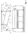
- the invention is in connection with a in the Fig. 1 schematically illustrated trough 10 for commercial laundries explained.
- the invention is, however, not limited thereto.
- the tray deficiency 10 shown has a frame with a lacking well and a rotating drivable mangle roller.
- the trough 10 can also have several mangle rolls and mangle troughs.
- the at least one mangle trough of the trough deficiency 10 is heated by steam, oil or another heat transfer medium.
- the heated mangle trough heats the wet laundry that passes between the mangle trough and the mangle drum when mangled. This largely vaporizes the residual moisture of the laundry. This residual moisture is absorbed by the ambient air of the mangle trough and removed as moist exhaust air.
- the moist exhaust air from the trough deficiency 10 has accompanying substances, such as lint from the laundry, lack wax, detergent residues or the like.
- the moist exhaust air from the trough deficiency 10 is supplied with the accompanying substances to an input end 11 of a heat exchanger 12.
- the moist exhaust air from the trough 10 is deprived of heat energy in the heat exchanger 12.
- the exhaust air is cooled, so that the moisture condenses in the exhaust air at least partially.
- a heat transfer fluid which is preferably water (hot water, fresh water or the like) for the laundry, which is required for the operation of other laundry machines, such as washing machines.
- the heat exchanger 12 has a plurality of preferably identically formed heat exchanger plates 13, which are arranged in a common elongated, cuboid housing 14.
- the output end 16 of the heat exchanger 12 is thereby at a lower level than the input end 11 of the heat exchanger 12.
- the housing 14 of the heat exchanger 12 is surrounded by a three-dimensional frame 17.
- the heat exchanger 12 with the frame 17 in the longitudinal direction 15 obliquely downwardly relative to the flow direction of the moist air suspended on preferably horizontal beams 18.
- the carriers 18 are located under a hall roof or are part of the hall roof.
- the carriers 18 (like the heat exchanger 12) can also run obliquely.
- the frame 17 also carries connections, fittings and parts of pipelines for supplying the water to be heated to the heat exchanger 12 and the removal of the heated water in the illustrated embodiment.
- the frame 17 carries a condensate connection 19, with which the condensate and accompanying substances, which originate from the cooled exhaust air, can be discharged from the heat exchanger 12.
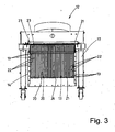
- the heat exchanger plates 13 are arranged in the housing 14 of the heat exchanger 12 according to the invention standing.
- the heat exchanger plates 13 are arranged in the housing 14 so that their elongated, rectangular heat exchanger surfaces 20 are perpendicular.
- the upper and lower longitudinal edges 21 of all heat exchanger surfaces 20 of the heat exchanger plates 13 follow the oblique, inclined course of the heat exchanger 12. Accordingly, the longitudinal edges 21 of the heat exchanger plates 13 and the heat exchanger surfaces 20 of the same inclined to the output end 16 of the heat exchanger 12. Die to the output end 16 of the heat exchanger 12 pointing ends of the longitudinal edges 21 are thereby deeper than the higher input end 11 facing ends of the longitudinal edges 21. It is also provided that at least the lower longitudinal edges 21 of all heat exchanger plates 13 are spaced from the bottom 26 of the housing 14.
- the heat exchanger surfaces 20 of all heat exchanger plates 13 are formed planar except for a structured surface due to their design.
- the heat exchanger plates 13 are arranged running at equal intervals to each other in parallel.
- flow passages 22 for the moist exhaust air flowing through the heat exchanger 12, including the accompanying substances in the exhaust air are formed between the mutually directed heat exchanger surfaces 20 of two adjacent heat exchanger plates 13.
- All flow channels 22 between the heat exchanger plates 13 are also perpendicular as the heat exchanger surface 20 of the heat exchanger plates 13.
- the flow channels 22 from the input end 11 of the heat exchanger 12 to the output end 16 of the heat exchanger 12 downwardly inclined.
- the same rectangular heat exchanger plates 13 are formed as double-walled cushion plates, the flow channels not shown in the interior of the figures for the flowing through the heat exchanger plates 13, to be heated liquid, especially water, have.
- Each heat exchanger plate 13 is formed of two thin plates, in particular plates 23, preferably made of stainless steel, such as stainless steel.
- the two sheets 23 of the respective heat exchanger plate 13 abut each other at their edges and are peripherally connected liquid-tight at the edges, in particular welded. Further, the sheets 23 are connected to each other by a plurality of welding spots which are distributed in a uniform pattern on the surface of the sheets 23 and the heat exchange surfaces 20 formed on the outer sides thereof, thereby causing the pillow-like structuring of the outer sides of the heat exchanger plates 13.
- In the areas between the welding points and the peripheral edges of the plates 23 of each heat exchanger plate 13 are spaced apart, so that between the welds a network of flow channels for the heat exchanger plates 13 flowing through the liquid to be heated is present.
- the moist exhaust air from the depression 10 is sucked with accompanying substances, in particular fluff, but possibly also lack wax and possibly detergent residues and other accumulating in a laundry when treating the laundry by-products, from the region of the trough 10 and through a Mangelab Kunststoffrohr Ober 24 to the input end 11th the heat exchanger 12 passed.
- the moist exhaust air then flows through the flow channels 21 between the heat exchanger plates 13 of the heat exchanger 12 to the lower end 16 of the heat exchanger 12.
- the moist exhaust air is not only cooled; At least part of the accompanying substances contained in the moist exhaust air, preferably a large part of the accompanying substances, are removed from the exhaust air in the region of the heat exchanger 12.
- the cooled exhaust air then leaves without accompanying substances, ie in the quasi-cleaned or filtered state, the heat exchanger 12 by its lower output end 16.
- the exhaust air then passes through a pipe 25 into the open or to an exhaust chimney.
- the heat exchanger 12 also a liquid to be heated, especially in the laundry for feeding laundry machines, such as washing machines, required service water or fresh water, directed.
- This is preferably hot water or fresh water at room temperature.
- the moist air from the trough 10 which can have temperatures up to 140 ° C, significantly cooled, namely to about 70 ° C, possibly also below. This creates condensate.
- the moist exhaust air with the accompanying substances therein flows in the heat exchanger 12 on the outside of the vertical heat exchanger surfaces 20 of the standing upright on the heat exchanger 12 heat exchanger plates 13 along. Because the moist exhaust air with the accompanying substances flows through the heat exchanger 12 in the longitudinal direction 15 and the heat exchanger plates 13 with the flow channels 22 formed between them for the moist exhaust air and the accompanying substances extend longitudinally through the heat exchanger 12, the heat exchanger surfaces 20 of all heat exchanger plates 13 equally moist Exhaust air brought from the trough deficiency 10 in contact, wherein the temperature of the exhaust air on the way longitudinally through the heat exchanger 12 on all heat exchanger surfaces 20 of the heat exchanger plates 13 is approximately equal.
- the impurities are at least largely separated from the exhaust air. This takes place in the heat exchanger 12, specifically during cooling of the exhaust air flowing through the heat exchanger 12. During this cooling, the exhaust air is separated from the impurities in the heat exchanger 12.
- the condensate takes along the accompanying substances in the moist exhaust air. The condensate serves, so to speak, as a means of liberating the moist exhaust air from the accompanying substances. In particular, the condensate washes the impurities at least for the most part from the moist exhaust air during the cooling of the same.
- the condensate absorbs the impurities separated off from the moist exhaust air, so that not only the condensate, but also the accompanying substances bound or entrained by it are deposited on the heat exchanger surfaces 20 of the heat exchanger plates 13. Due to the vertical, in the illustrated embodiment, vertical arrangement of the heat exchanger plates 13 in the housing 14 of the heat exchanger 12, which runs outside of the heat exchanger surfaces 20 heat exchanger plates 13th settling condensate with the accompanying substances on the heat exchanger surfaces 20 down to the bottom 26 of the housing 14 of the heat exchanger 12.
- the adhering to the structured outer sides of the formed as a cushion plates heat exchanger surfaces 20 accompanying contaminants of the moist exhaust air from the trough 10 are characterized by the condensate of the Washed off heat exchanger surfaces 20 and thereby the pillow-like structured heat exchanger surfaces 20 kept free of the accompanying substances and the condensate.
- the impurities are thus taken from the condensate during the flow from the heat exchanger surfaces 20.
- the condensate runs entraining the accompanying substances on the heat exchanger surfaces 20 of the heat exchanger plates 13 on the one hand down and on the other hand in the longitudinal direction 15 of the heat exchanger 12th towards the exit end 16 down.
- the condensate with the entrained by the outer walls of the heat exchanger plates 13 accompanying material collects first at the spaced above the bottom 26, obliquely arranged longitudinal edges 21 of the heat exchanger plates 13, wherein due to the inclined course of the heat exchanger plates 13 at the inclined longitudinal edges 21, the condensate with the the heat exchanger surfaces 20 of the heat exchanger plates 13 washed off accompanying material also in the longitudinal direction 15 to the lower-lying outlet end 16 flows. If larger quantities of condensate have formed, they drip off the lower longitudinal edges 21 of the heat exchanger plates 13 and reach the bottom 26 of the housing 14.
- the condensate collecting on the bottom 26 with the accompanying substances entrained by the outer walls of the heat exchanger plates 13 then flows into Longitudinal direction 15 of the heat exchanger 12 to the lower end 16 of the same.
- the condensate also entrained from the moist exhaust air accompanying substances, so that the condensate together with the accompanying substances after draining from the oblique lower longitudinal edges 21 of the stationary heat exchanger plates 13 via the sloping bottom 26 of the housing 14 of the heat exchanger 12 to the output end 16th the heat exchanger 12 flows.
- the heat exchanger 12 is continuously freed from the condensate with the accompanying substances, which are bound in particular in the condensate.
- the condensate with the accompanying substances can then be diverted to a drain, for example a sewer.
- a drain for example a sewer.
- filter the condensate ie remove the accompanying substances, at least some impurities such as lint, from the condensate outside the heat exchanger 12 and then reuse the at least largely freed of accompanying substances liquid condensate, essentially warm water, for example, together with the preheated in the heat exchanger 12 of the still hot exhaust air from the trough 10 lack of liquid.
- the invention has been described above together with a tray 10 lack. However, the invention is also suitable for other heated laundry machines, in particular finishers, dryers or the like.
Landscapes
- Engineering & Computer Science (AREA)
- Textile Engineering (AREA)
- Detail Structures Of Washing Machines And Dryers (AREA)
- Heat-Exchange Devices With Radiators And Conduit Assemblies (AREA)
- Accessory Of Washing/Drying Machine, Commercial Washing/Drying Machine, Other Washing/Drying Machine (AREA)
Applications Claiming Priority (1)
| Application Number | Priority Date | Filing Date | Title |
|---|---|---|---|
| DE102008054104A DE102008054104A1 (de) | 2008-10-31 | 2008-10-31 | Verfahren und Vorrichtung zum Aufbereiten der Abluft von beheizten Wäschereimaschinen |
Publications (2)
| Publication Number | Publication Date |
|---|---|
| EP2182106A1 EP2182106A1 (de) | 2010-05-05 |
| EP2182106B1 true EP2182106B1 (de) | 2014-03-26 |
Family
ID=41606711
Family Applications (1)
| Application Number | Title | Priority Date | Filing Date |
|---|---|---|---|
| EP09013263.0A Active EP2182106B1 (de) | 2008-10-31 | 2009-10-21 | Verfahren und Vorrichtung zum Aufbereiten der Abluft von beheizten Wäschereimaschinen |
Country Status (4)
| Country | Link |
|---|---|
| US (1) | US8567090B2 (da) |
| EP (1) | EP2182106B1 (da) |
| DE (1) | DE102008054104A1 (da) |
| DK (1) | DK2182106T3 (da) |
Families Citing this family (9)
| Publication number | Priority date | Publication date | Assignee | Title |
|---|---|---|---|---|
| DE102006020003A1 (de) * | 2006-04-26 | 2007-10-31 | Herbert Kannegiesser Gmbh | Verfahren zur Rückgewinnung der von Wäschereimaschinen abgegebenen Wärmeenergie |
| DE102007043212A1 (de) * | 2007-03-19 | 2008-09-25 | Herbert Kannegieser Gmbh | Verfahren zur Rückgewinnung der Abwärme von beheizten Wäschereimaschinen |
| DE102008054104A1 (de) * | 2008-10-31 | 2010-05-06 | Herbert Kannegiesser Gmbh | Verfahren und Vorrichtung zum Aufbereiten der Abluft von beheizten Wäschereimaschinen |
| KR102063765B1 (ko) * | 2013-06-20 | 2020-03-02 | 엘지전자 주식회사 | 폐열 회수수단을 갖는 건조기 |
| DE102014010498B4 (de) | 2014-07-17 | 2026-01-15 | Herbert Kannegiesser Gmbh | Verfahren zum Trocknen von Wäsche und Trockner |
| NO2751710T3 (da) * | 2015-05-22 | 2017-12-30 | ||
| JP6693441B2 (ja) * | 2017-02-27 | 2020-05-13 | オムロン株式会社 | 電子装置およびその製造方法 |
| EP4634600A1 (de) * | 2023-02-08 | 2025-10-22 | Mathias Kleine | Rückgewinnungsvorrichtung |
| DE102024132446A1 (de) * | 2024-11-07 | 2026-05-07 | Wilhelm Bringewatt | Wäschereisystem mit effektiver fortluftnutzung und verfahren hierzu |
Family Cites Families (23)
| Publication number | Priority date | Publication date | Assignee | Title |
|---|---|---|---|---|
| DE2450497C2 (de) * | 1974-10-24 | 1985-09-12 | Babcock Textilmaschinen GmbH, 2105 Seevetal | Vorrichtung für die Reinigung und Wärmerückgewinnung aus der Abluft bei Wärmebehandlungs- und Trocknungsanlagen |
| US4112590A (en) * | 1975-07-02 | 1978-09-12 | August Lepper, Maschinen- Und Apparatebau Gmbh | Combined drum washer and drying arrangement |
| US4326344A (en) * | 1976-11-08 | 1982-04-27 | Q-Dot Corporation | Laundry drying system and method |
| US4461345A (en) * | 1979-10-22 | 1984-07-24 | Kool-Fire Limited | Heat-augmented heat exchanger system |
| IT1155193B (it) * | 1982-05-10 | 1987-01-21 | Indesit | Apparecchio essicatore particolarmente armadio asciugabiancheria |
| DD210966A1 (de) * | 1982-10-08 | 1984-06-27 | Heinrich Landgraf | Rekuperativer waermeuebertrager |
| US4548262A (en) * | 1983-03-31 | 1985-10-22 | Hull Francis R | Condensing gas-to-gas heat exchanger |
| DE8318395U1 (de) * | 1983-06-24 | 1983-10-20 | Bosch-Siemens Hausgeräte GmbH, 7000 Stuttgart | Haushalt-waeschetrockner |
| US4660627A (en) * | 1984-07-16 | 1987-04-28 | Deck Brent D | Heat exchanging with slowly rotating finned elements |
| US4928749A (en) * | 1985-05-08 | 1990-05-29 | Industrial Energy Corporation | Heat exchange recovery method |
| DE4020265C1 (da) * | 1990-06-26 | 1991-04-18 | Mercedes-Benz Aktiengesellschaft, 7000 Stuttgart, De | |
| DE4030195A1 (de) * | 1990-09-24 | 1992-03-26 | Bosch Siemens Hausgeraete | Haushalt-waeschetrockner mit einem kondensator |
| DE4032904A1 (de) * | 1990-10-17 | 1992-04-23 | Zanker Gmbh | Waeschetrockner |
| US5046478A (en) * | 1990-11-30 | 1991-09-10 | Raytheon Company | Recuperative furnace system for space air and domestic hot water |
| DE19600489C2 (de) * | 1995-01-13 | 2003-04-03 | Miele & Cie | Kondensationswäschetrockner |
| DE69619471T2 (de) * | 1995-11-20 | 2002-08-01 | Electrolux Zanussi S.P.A., Pordenone | Verfahren zur Herstellung eines Kreuzstrom-Wärmetauschers |
| US20050120715A1 (en) * | 1997-12-23 | 2005-06-09 | Christion School Of Technology Charitable Foundation Trust | Heat energy recapture and recycle and its new applications |
| DE102007004100B4 (de) * | 2007-01-26 | 2011-12-29 | Joachim Krause | Verfahren zum Filtern von Schmutzpartikeln |
| DE102007043212A1 (de) * | 2007-03-19 | 2008-09-25 | Herbert Kannegieser Gmbh | Verfahren zur Rückgewinnung der Abwärme von beheizten Wäschereimaschinen |
| DE102007018784A1 (de) | 2007-04-20 | 2008-10-23 | BSH Bosch und Siemens Hausgeräte GmbH | Automatische, zum Trocknen eingerichtete Waschmaschine |
| JP2009195362A (ja) * | 2008-02-20 | 2009-09-03 | Panasonic Corp | 衣類乾燥装置 |
| DE102008054104A1 (de) * | 2008-10-31 | 2010-05-06 | Herbert Kannegiesser Gmbh | Verfahren und Vorrichtung zum Aufbereiten der Abluft von beheizten Wäschereimaschinen |
| CN102822410B (zh) * | 2010-08-09 | 2015-06-17 | Lg电子株式会社 | 干衣机 |
-
2008
- 2008-10-31 DE DE102008054104A patent/DE102008054104A1/de not_active Withdrawn
-
2009
- 2009-10-21 EP EP09013263.0A patent/EP2182106B1/de active Active
- 2009-10-21 DK DK09013263.0T patent/DK2182106T3/da active
- 2009-10-28 US US12/607,526 patent/US8567090B2/en not_active Expired - Fee Related
Also Published As
| Publication number | Publication date |
|---|---|
| DK2182106T3 (da) | 2014-06-30 |
| US8567090B2 (en) | 2013-10-29 |
| DE102008054104A1 (de) | 2010-05-06 |
| EP2182106A1 (de) | 2010-05-05 |
| US20100107438A1 (en) | 2010-05-06 |
Similar Documents
| Publication | Publication Date | Title |
|---|---|---|
| EP2182106A1 (de) | Verfahren und Vorrichtung zum Aufbereiten der Abluft von beheizten Wäschereimaschinen | |
| DE2659647C2 (de) | Vorrichtung zur Abfuhr von Rauch, Dämpfen und Fetten für geschlossene Räume | |
| DE2533759C3 (de) | Vorrichtung zur Behandlung des Abwassers von Großwäschereien, Brauereien o.dgl. | |
| DE4208665C2 (de) | Verfahren zum Trocknen von Gegenständen sowie Anlage zur Durchführung des Verfahrens | |
| DE3738031A1 (de) | Verfahren und vorrichtung zum entfernen von flusen aus einem als waermetauscher ausgebildeten kondenswasser-abscheider | |
| DE102007043212A1 (de) | Verfahren zur Rückgewinnung der Abwärme von beheizten Wäschereimaschinen | |
| DE102007034000B4 (de) | Wärmetauscher und Kondensationswäschetrockner mit diesem | |
| EP0838190A2 (de) | Durchlaufgeschirrspülvorrichtung sowie Verfahren zum Reinigen von Geschirr- und/oder Tabletteilen | |
| EP1920102B1 (de) | Wäschetrockner mit einem flusenfilter | |
| EP3538700B1 (de) | Verfahren und vorrichtung zur behandlung von wäsche | |
| EP2924379B1 (de) | Verfahren und Vorrichtung zum Behandeln von Matratzen oder dergleichen | |
| DE102004030015A1 (de) | Spülmaschinen-Betriebsverfahren und Transportspülmaschine | |
| DE102004030014A1 (de) | Spülmaschinen-Betriebsverfahren und Transportspülmaschine | |
| DE3911959A1 (de) | Verfahren und vorrichtung zur behandlung von tierischen haaren und federn bzw. pflanzlichen fasern | |
| DE102007004100B4 (de) | Verfahren zum Filtern von Schmutzpartikeln | |
| DE112013005028T5 (de) | Verbessertes Quetschverfahren für ölhaltiges Material | |
| DD210966A1 (de) | Rekuperativer waermeuebertrager | |
| EP2335000B1 (de) | Vorrichtung zur wärmerückgewinnung an einer anlage zur thermischen behandlung von textilen warenbahnen | |
| DE102012221914B4 (de) | Filteranordnung für eine Wäschebehandlungsmaschine | |
| DE4428738A1 (de) | Durchlauf-Geschirrspülmaschine | |
| EP3147404A1 (de) | Wäschetrockner mit wasserzuführung | |
| DE62213C (de) | Verdampf- und Destillirapparat. (2 | |
| DE4342108C2 (de) | Verfahren und Vorrichtung zum Endbehandeln, insbesondere zum Trocknen, von vorgereinigten und mit Flüssigkeit benetzten Teilen | |
| DE4307608A1 (de) | Verfahren und Vorrichtung zur Energienutzung von Rauchgasen in kohlegefeuerten Kraftwerken | |
| WO2003025265A1 (de) | Vorrichtung zum kontinuierlichen waschen von schmutziger, fetthaltiger wolle |
Legal Events
| Date | Code | Title | Description |
|---|---|---|---|
| PUAI | Public reference made under article 153(3) epc to a published international application that has entered the european phase |
Free format text: ORIGINAL CODE: 0009012 |
|
| AK | Designated contracting states |
Kind code of ref document: A1 Designated state(s): AT BE BG CH CY CZ DE DK EE ES FI FR GB GR HR HU IE IS IT LI LT LU LV MC MK MT NL NO PL PT RO SE SI SK SM TR |
|
| AX | Request for extension of the european patent |
Extension state: AL BA RS |
|
| 17P | Request for examination filed |
Effective date: 20101007 |
|
| 17Q | First examination report despatched |
Effective date: 20101108 |
|
| GRAP | Despatch of communication of intention to grant a patent |
Free format text: ORIGINAL CODE: EPIDOSNIGR1 |
|
| GRAP | Despatch of communication of intention to grant a patent |
Free format text: ORIGINAL CODE: EPIDOSNIGR1 |
|
| INTG | Intention to grant announced |
Effective date: 20130923 |
|
| INTG | Intention to grant announced |
Effective date: 20131011 |
|
| GRAS | Grant fee paid |
Free format text: ORIGINAL CODE: EPIDOSNIGR3 |
|
| GRAA | (expected) grant |
Free format text: ORIGINAL CODE: 0009210 |
|
| AK | Designated contracting states |
Kind code of ref document: B1 Designated state(s): AT BE BG CH CY CZ DE DK EE ES FI FR GB GR HR HU IE IS IT LI LT LU LV MC MK MT NL NO PL PT RO SE SI SK SM TR |
|
| REG | Reference to a national code |
Ref country code: GB Ref legal event code: FG4D Free format text: NOT ENGLISH |
|
| REG | Reference to a national code |
Ref country code: CH Ref legal event code: EP |
|
| REG | Reference to a national code |
Ref country code: AT Ref legal event code: REF Ref document number: 659077 Country of ref document: AT Kind code of ref document: T Effective date: 20140415 |
|
| REG | Reference to a national code |
Ref country code: IE Ref legal event code: FG4D Free format text: LANGUAGE OF EP DOCUMENT: GERMAN |
|
| REG | Reference to a national code |
Ref country code: DE Ref legal event code: R096 Ref document number: 502009009055 Country of ref document: DE Effective date: 20140508 |
|
| REG | Reference to a national code |
Ref country code: CH Ref legal event code: NV Representative=s name: R. A. EGLI AND CO. PATENTANWAELTE, CH |
|
| REG | Reference to a national code |
Ref country code: NL Ref legal event code: T3 |
|
| REG | Reference to a national code |
Ref country code: DK Ref legal event code: T3 Effective date: 20140623 |
|
| PG25 | Lapsed in a contracting state [announced via postgrant information from national office to epo] |
Ref country code: LT Free format text: LAPSE BECAUSE OF FAILURE TO SUBMIT A TRANSLATION OF THE DESCRIPTION OR TO PAY THE FEE WITHIN THE PRESCRIBED TIME-LIMIT Effective date: 20140326 Ref country code: NO Free format text: LAPSE BECAUSE OF FAILURE TO SUBMIT A TRANSLATION OF THE DESCRIPTION OR TO PAY THE FEE WITHIN THE PRESCRIBED TIME-LIMIT Effective date: 20140626 |
|
| REG | Reference to a national code |
Ref country code: LT Ref legal event code: MG4D |
|
| PG25 | Lapsed in a contracting state [announced via postgrant information from national office to epo] |
Ref country code: FI Free format text: LAPSE BECAUSE OF FAILURE TO SUBMIT A TRANSLATION OF THE DESCRIPTION OR TO PAY THE FEE WITHIN THE PRESCRIBED TIME-LIMIT Effective date: 20140326 Ref country code: SE Free format text: LAPSE BECAUSE OF FAILURE TO SUBMIT A TRANSLATION OF THE DESCRIPTION OR TO PAY THE FEE WITHIN THE PRESCRIBED TIME-LIMIT Effective date: 20140326 |
|
| PG25 | Lapsed in a contracting state [announced via postgrant information from national office to epo] |
Ref country code: LV Free format text: LAPSE BECAUSE OF FAILURE TO SUBMIT A TRANSLATION OF THE DESCRIPTION OR TO PAY THE FEE WITHIN THE PRESCRIBED TIME-LIMIT Effective date: 20140326 Ref country code: HR Free format text: LAPSE BECAUSE OF FAILURE TO SUBMIT A TRANSLATION OF THE DESCRIPTION OR TO PAY THE FEE WITHIN THE PRESCRIBED TIME-LIMIT Effective date: 20140326 |
|
| PG25 | Lapsed in a contracting state [announced via postgrant information from national office to epo] |
Ref country code: CZ Free format text: LAPSE BECAUSE OF FAILURE TO SUBMIT A TRANSLATION OF THE DESCRIPTION OR TO PAY THE FEE WITHIN THE PRESCRIBED TIME-LIMIT Effective date: 20140326 Ref country code: CY Free format text: LAPSE BECAUSE OF FAILURE TO SUBMIT A TRANSLATION OF THE DESCRIPTION OR TO PAY THE FEE WITHIN THE PRESCRIBED TIME-LIMIT Effective date: 20140326 Ref country code: IS Free format text: LAPSE BECAUSE OF FAILURE TO SUBMIT A TRANSLATION OF THE DESCRIPTION OR TO PAY THE FEE WITHIN THE PRESCRIBED TIME-LIMIT Effective date: 20140726 Ref country code: BG Free format text: LAPSE BECAUSE OF FAILURE TO SUBMIT A TRANSLATION OF THE DESCRIPTION OR TO PAY THE FEE WITHIN THE PRESCRIBED TIME-LIMIT Effective date: 20140626 Ref country code: RO Free format text: LAPSE BECAUSE OF FAILURE TO SUBMIT A TRANSLATION OF THE DESCRIPTION OR TO PAY THE FEE WITHIN THE PRESCRIBED TIME-LIMIT Effective date: 20140326 Ref country code: EE Free format text: LAPSE BECAUSE OF FAILURE TO SUBMIT A TRANSLATION OF THE DESCRIPTION OR TO PAY THE FEE WITHIN THE PRESCRIBED TIME-LIMIT Effective date: 20140326 |
|
| PG25 | Lapsed in a contracting state [announced via postgrant information from national office to epo] |
Ref country code: PL Free format text: LAPSE BECAUSE OF FAILURE TO SUBMIT A TRANSLATION OF THE DESCRIPTION OR TO PAY THE FEE WITHIN THE PRESCRIBED TIME-LIMIT Effective date: 20140326 Ref country code: ES Free format text: LAPSE BECAUSE OF FAILURE TO SUBMIT A TRANSLATION OF THE DESCRIPTION OR TO PAY THE FEE WITHIN THE PRESCRIBED TIME-LIMIT Effective date: 20140326 Ref country code: SK Free format text: LAPSE BECAUSE OF FAILURE TO SUBMIT A TRANSLATION OF THE DESCRIPTION OR TO PAY THE FEE WITHIN THE PRESCRIBED TIME-LIMIT Effective date: 20140326 |
|
| PG25 | Lapsed in a contracting state [announced via postgrant information from national office to epo] |
Ref country code: PT Free format text: LAPSE BECAUSE OF FAILURE TO SUBMIT A TRANSLATION OF THE DESCRIPTION OR TO PAY THE FEE WITHIN THE PRESCRIBED TIME-LIMIT Effective date: 20140728 |
|
| REG | Reference to a national code |
Ref country code: DE Ref legal event code: R097 Ref document number: 502009009055 Country of ref document: DE |
|
| PLBE | No opposition filed within time limit |
Free format text: ORIGINAL CODE: 0009261 |
|
| STAA | Information on the status of an ep patent application or granted ep patent |
Free format text: STATUS: NO OPPOSITION FILED WITHIN TIME LIMIT |
|
| 26N | No opposition filed |
Effective date: 20150106 |
|
| PGFP | Annual fee paid to national office [announced via postgrant information from national office to epo] |
Ref country code: IT Payment date: 20141010 Year of fee payment: 6 |
|
| REG | Reference to a national code |
Ref country code: DE Ref legal event code: R097 Ref document number: 502009009055 Country of ref document: DE Effective date: 20150106 |
|
| PG25 | Lapsed in a contracting state [announced via postgrant information from national office to epo] |
Ref country code: LU Free format text: LAPSE BECAUSE OF FAILURE TO SUBMIT A TRANSLATION OF THE DESCRIPTION OR TO PAY THE FEE WITHIN THE PRESCRIBED TIME-LIMIT Effective date: 20141021 Ref country code: MC Free format text: LAPSE BECAUSE OF FAILURE TO SUBMIT A TRANSLATION OF THE DESCRIPTION OR TO PAY THE FEE WITHIN THE PRESCRIBED TIME-LIMIT Effective date: 20140326 |
|
| REG | Reference to a national code |
Ref country code: IE Ref legal event code: MM4A |
|
| PG25 | Lapsed in a contracting state [announced via postgrant information from national office to epo] |
Ref country code: SI Free format text: LAPSE BECAUSE OF FAILURE TO SUBMIT A TRANSLATION OF THE DESCRIPTION OR TO PAY THE FEE WITHIN THE PRESCRIBED TIME-LIMIT Effective date: 20140326 |
|
| REG | Reference to a national code |
Ref country code: FR Ref legal event code: PLFP Year of fee payment: 7 |
|
| PG25 | Lapsed in a contracting state [announced via postgrant information from national office to epo] |
Ref country code: IE Free format text: LAPSE BECAUSE OF NON-PAYMENT OF DUE FEES Effective date: 20141021 |
|
| PGFP | Annual fee paid to national office [announced via postgrant information from national office to epo] |
Ref country code: CH Payment date: 20151012 Year of fee payment: 7 Ref country code: GB Payment date: 20151021 Year of fee payment: 7 |
|
| PGFP | Annual fee paid to national office [announced via postgrant information from national office to epo] |
Ref country code: FR Payment date: 20151008 Year of fee payment: 7 |
|
| PG25 | Lapsed in a contracting state [announced via postgrant information from national office to epo] |
Ref country code: SM Free format text: LAPSE BECAUSE OF FAILURE TO SUBMIT A TRANSLATION OF THE DESCRIPTION OR TO PAY THE FEE WITHIN THE PRESCRIBED TIME-LIMIT Effective date: 20140326 |
|
| PG25 | Lapsed in a contracting state [announced via postgrant information from national office to epo] |
Ref country code: GR Free format text: LAPSE BECAUSE OF FAILURE TO SUBMIT A TRANSLATION OF THE DESCRIPTION OR TO PAY THE FEE WITHIN THE PRESCRIBED TIME-LIMIT Effective date: 20140627 |
|
| PG25 | Lapsed in a contracting state [announced via postgrant information from national office to epo] |
Ref country code: HU Free format text: LAPSE BECAUSE OF FAILURE TO SUBMIT A TRANSLATION OF THE DESCRIPTION OR TO PAY THE FEE WITHIN THE PRESCRIBED TIME-LIMIT; INVALID AB INITIO Effective date: 20091021 Ref country code: IT Free format text: LAPSE BECAUSE OF NON-PAYMENT OF DUE FEES Effective date: 20151021 Ref country code: MT Free format text: LAPSE BECAUSE OF FAILURE TO SUBMIT A TRANSLATION OF THE DESCRIPTION OR TO PAY THE FEE WITHIN THE PRESCRIBED TIME-LIMIT Effective date: 20140326 Ref country code: TR Free format text: LAPSE BECAUSE OF FAILURE TO SUBMIT A TRANSLATION OF THE DESCRIPTION OR TO PAY THE FEE WITHIN THE PRESCRIBED TIME-LIMIT Effective date: 20140326 |
|
| REG | Reference to a national code |
Ref country code: CH Ref legal event code: PL |
|
| GBPC | Gb: european patent ceased through non-payment of renewal fee |
Effective date: 20161021 |
|
| REG | Reference to a national code |
Ref country code: FR Ref legal event code: ST Effective date: 20170630 |
|
| PG25 | Lapsed in a contracting state [announced via postgrant information from national office to epo] |
Ref country code: CH Free format text: LAPSE BECAUSE OF NON-PAYMENT OF DUE FEES Effective date: 20161031 Ref country code: GB Free format text: LAPSE BECAUSE OF NON-PAYMENT OF DUE FEES Effective date: 20161021 Ref country code: LI Free format text: LAPSE BECAUSE OF NON-PAYMENT OF DUE FEES Effective date: 20161031 Ref country code: FR Free format text: LAPSE BECAUSE OF NON-PAYMENT OF DUE FEES Effective date: 20161102 |
|
| PG25 | Lapsed in a contracting state [announced via postgrant information from national office to epo] |
Ref country code: MK Free format text: LAPSE BECAUSE OF FAILURE TO SUBMIT A TRANSLATION OF THE DESCRIPTION OR TO PAY THE FEE WITHIN THE PRESCRIBED TIME-LIMIT Effective date: 20140326 |
|
| PGFP | Annual fee paid to national office [announced via postgrant information from national office to epo] |
Ref country code: DK Payment date: 20201012 Year of fee payment: 12 Ref country code: AT Payment date: 20200925 Year of fee payment: 12 |
|
| REG | Reference to a national code |
Ref country code: DK Ref legal event code: EBP Effective date: 20211031 |
|
| REG | Reference to a national code |
Ref country code: AT Ref legal event code: MM01 Ref document number: 659077 Country of ref document: AT Kind code of ref document: T Effective date: 20211021 |
|
| PG25 | Lapsed in a contracting state [announced via postgrant information from national office to epo] |
Ref country code: AT Free format text: LAPSE BECAUSE OF NON-PAYMENT OF DUE FEES Effective date: 20211021 |
|
| PG25 | Lapsed in a contracting state [announced via postgrant information from national office to epo] |
Ref country code: DK Free format text: LAPSE BECAUSE OF NON-PAYMENT OF DUE FEES Effective date: 20211031 |
|
| P01 | Opt-out of the competence of the unified patent court (upc) registered |
Effective date: 20230529 |
|
| PGFP | Annual fee paid to national office [announced via postgrant information from national office to epo] |
Ref country code: NL Payment date: 20251023 Year of fee payment: 17 |
|
| PGFP | Annual fee paid to national office [announced via postgrant information from national office to epo] |
Ref country code: DE Payment date: 20251029 Year of fee payment: 17 |
|
| PGFP | Annual fee paid to national office [announced via postgrant information from national office to epo] |
Ref country code: BE Payment date: 20251022 Year of fee payment: 17 |