EP2182116A2 - Endlose flexible Tragestrukturanordnung - Google Patents
Endlose flexible Tragestrukturanordnung Download PDFInfo
- Publication number
- EP2182116A2 EP2182116A2 EP08169582A EP08169582A EP2182116A2 EP 2182116 A2 EP2182116 A2 EP 2182116A2 EP 08169582 A EP08169582 A EP 08169582A EP 08169582 A EP08169582 A EP 08169582A EP 2182116 A2 EP2182116 A2 EP 2182116A2
- Authority
- EP
- European Patent Office
- Prior art keywords
- cell
- support structure
- surface support
- upright walls
- recessed portion
- Prior art date
- Legal status (The legal status is an assumption and is not a legal conclusion. Google has not performed a legal analysis and makes no representation as to the accuracy of the status listed.)
- Withdrawn
Links
Images



Classifications
-
- E—FIXED CONSTRUCTIONS
- E01—CONSTRUCTION OF ROADS, RAILWAYS, OR BRIDGES
- E01C—CONSTRUCTION OF, OR SURFACES FOR, ROADS, SPORTS GROUNDS, OR THE LIKE; MACHINES OR AUXILIARY TOOLS FOR CONSTRUCTION OR REPAIR
- E01C5/00—Pavings made of prefabricated single units
- E01C5/20—Pavings made of prefabricated single units made of units of plastics, e.g. concrete with plastics, linoleum
-
- E—FIXED CONSTRUCTIONS
- E01—CONSTRUCTION OF ROADS, RAILWAYS, OR BRIDGES
- E01C—CONSTRUCTION OF, OR SURFACES FOR, ROADS, SPORTS GROUNDS, OR THE LIKE; MACHINES OR AUXILIARY TOOLS FOR CONSTRUCTION OR REPAIR
- E01C9/00—Special pavings; Pavings for special parts of roads or airfields
- E01C9/004—Pavings specially adapted for allowing vegetation
-
- Y—GENERAL TAGGING OF NEW TECHNOLOGICAL DEVELOPMENTS; GENERAL TAGGING OF CROSS-SECTIONAL TECHNOLOGIES SPANNING OVER SEVERAL SECTIONS OF THE IPC; TECHNICAL SUBJECTS COVERED BY FORMER USPC CROSS-REFERENCE ART COLLECTIONS [XRACs] AND DIGESTS
- Y10—TECHNICAL SUBJECTS COVERED BY FORMER USPC
- Y10T—TECHNICAL SUBJECTS COVERED BY FORMER US CLASSIFICATION
- Y10T428/00—Stock material or miscellaneous articles
- Y10T428/249921—Web or sheet containing structurally defined element or component
Definitions
- Multiple embodiments relate to a continuous flexible support structure assembly for use on and within various surfaces.
- Various surfaces are often utilized as ground, walking or roofing surfaces, such as turf grass, soil and/or gravel. Such materials are often subject to migration and/or erosion. Additionally, in areas of high pedestrian and/or vehicle traffic, surface stabilization, traction support and/or load weight support may be necessary to alleviate compaction and wear damage to the ground surface. Furthermore, adequate drainage is required for the various surfaces so that precipitation and other liquids do not stand on the various surfaces.
- a surface support structure is provided with at least one cell having a plurality of upright walls.
- a first wall of the plurality of upright walls has a recessed portion forming at least a portion to allow extension and contraction in multiple directions of the at least one cell.
- the plurality of upright walls of the at least one cell define a perimeter such that the recessed portion extends towards a second wall of the plurality of upright walls and is within the perimeter.
- a method of manufacturing is disclosed.
- a first surface support structure is molded with a first plurality of cells formed therein.
- the first plurality of cells each have a first plurality of upright walls.
- a first wall of the first plurality of upright walls has a recessed portion to allow extension and contraction in multiple directions of the first plurality of cells.
- a second surface support structure is molded with a second plurality of cells formed therein.
- the second plurality of cells each have a second plurality of upright walls.
- a first wall of the second plurality of upright walls has a recessed portion to allow extension and contraction in multiple directions of the second plurality of cells.
- the first surface support structure is joined to the second surface support structure.
- a surface support structure assembly has at least one cell having a first plurality of upright walls.
- a first wall of the first plurality of upright walls has a recessed portion to allow extension and contraction in multiple directions of the at least one cell.
- a second surface support structure has at least one cell with a second plurality of upright walls.
- a first wall of the second plurality of upright walls has a recessed portion to allow extension and contraction in multiple directions of the at least one cell. The first surface support structure and the second surface support structure are joined together.
- the surface support structure 10 can be employed on and/or within various surfaces to serve as a reinforcing paver with fully integrated flexibility to follow accurately ground topography and offering easy installation performance.
- the various surfaces include but are not limited to outdoor ground surfaces and roof or indoor surfaces having turf grass, soil, dirt and/or gravel.
- the surface support structure 10 can be implemented on and/or within any desired surface.
- multiple surface support structures 10 are employed on and/or within the ground surface.
- the term “within” it should be understood to encompass partially within such that a portion of the surface support structure 10 is under the ground while another portion is above (or visible on) the ground surface, and totally within such that the entire surface support structure 10 is below the ground surface.
- the surface support structure 10 can inhibit migration and/or erosion of the ground surface, and provide traction support and/or load weight support of the ground surface. Additionally, the open configuration of the surface support structure 10, which is discussed further below, allows for proper storm precipitation management so that precipitation can drain through the surface support structure 10 to inhibit the ground surface flooding.
- the surface support structure 10 can move in any direction along the x-axis X, the y-axis Y, and/or the z-axis Z to fit on and/or within different topographies of various ground surfaces.
- the surface support structure 10 is installed on top of an existing a ground surface, such as turf grass, so that the turf grass can grow around the surface support structure 10.
- the surface support structure 10 is installed within a ground surface, such as gravel, so that the gravel is under and/or within the surface support structure 10 and the surface support structure 10 supports the ground surface.
- the surface support structure 10 is filled with soil and fertilizer to allow grass to grow over the surface support structure 10.
- the surface support structure 10 can be utilized on any desired surface in a multitude of ways.
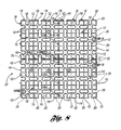
- the surface support structure 10 is integrally formed into multiple cells 12. As with the example surface support structures 10 illustrated in Figures 1-5 , nine integrally formed cells 12 may be injection molded in a single shot molding process of the surface support structure 10. As illustrated in Figure 6 , six integrally formed cells 12 may be formed as one surface support structure 10. However, it should be understood that the number of cells 12 can vary as desired. In at least the illustrated embodiment, the cells 12 may be oriented along the x-axis X and the y-axis Y as illustrated in Figure 1 , and may form a square having an equal amount of cells 12 displaced along the x-axis X and the y-axis Y.
- the surface support structure 10 has a size of approximately fifty centimeters by fifty centimeters. In other embodiments, the surface support structure 10 can have various lengths (along the x-axis X) and/or widths (along the y-axis Y) as desired. In one embodiment, the surface support structure 10 has a length of ten to one hundred and fifty centimeters and/or a width of ten to one hundred and fifty centimeters. In one embodiment, the surface support structure 10 has a length and/or a width of forty to one hundred centimeters. Of course, any suitable amount, orientation and size of the cells 12 and/or surface support structure 10 are contemplated within the scope of the disclosed embodiments.
- the cells 12 of the surface support structure 10 are integrally formed out of a plastic material, such as a polyethylene.
- a plastic material such as a polyethylene.
- Polyethylene is a suitable material for the cells 12 of the surface support structure 10 as it is a relatively strong material that retains shape while being elastic to allow for some movement of each cell 12 of the surface support structure 10.
- a flexible material may be employed to form the cells 12 of the support structure 10, the configuration of the cells 12 of the surface support structure 10, discussed below, allow the surface support structure 10 to move.
- other recycled plastics, non-recycled plastics, polymers and/or additives can be employed to form each cell 12 of the surface support structure 10 depending on the mechanical properties desired.
- the cells 12 have four integrally formed upright walls 14, 15.
- the upright walls 14, 15 provide traction support and/or load weight support in the ground surface that the surface support structure 10 is installed on or within.
- the cells 12 may have outer upright walls 14 and/or inner upright walls 15.
- the outer upright walls 14 may be similar and/or the same as the inner upright walls 15, while having different locations.
- the upright walls 14, 15 of each cell 12 may be continuous with upright walls 14, 15 of adjacent cells 12 so that repetition materials and increased thickness for the upright walls 14, 15 is not required.
- the upright walls 14, 15 may have any desired thickness. Since the upright walls 14, 15 of each cell may be integrally formed with upright walls 14, 15 of adjacent cells, material costs are reduced.
- the upright walls 14, 15 may have a height of two and a half centimeters. In another embodiment, the upright walls 14, 15 may have a height of five centimeters. In yet another embodiment, the upright walls 14, 15 have a height of seven centimeters. In still another embodiment, the upright walls 14, 15 have a height of one centimeter. Of course, any suitable height for the upright walls 14, 15 is contemplated within the scope of the disclosed embodiments.
- each upright wall 14, 15 includes a recessed portion 16 defining a recess therein.
- the recessed portions 16 forms a portion of each upright wall 14, 15 to allow movement in along the x-axis X, the y-axis Y and the z-axis Z, which allows each cell 12 to be flexible.
- each upright wall 14, 15 is illustrated with a recessed portion 16, recessed portions 16 may not be formed within each upright wall 14, 15. Any amount of recessed portions 16 may be formed in each cell 12 so that each cell 12 has at least one recessed portion 16. As illustrated in Figures 1-3 , the recessed portion 16 of each cell 12 may have an arcuate shape, which allows movement of the cell 12.
- the arcuate shape of the recessed portions 16 of each cell 12 may have an omega shape to allow movement of the cell 12.
- the recessed portions 16 of each cell 12 may have partial polygonal shape, allowing movement of the cell 12.
- the recessed portions 16 have a partial triangular shape to allow movement of the cell 12.
- the recessed portions 16 are provided in the corners of the upright walls 14, 15.
- the recessed portions 16 may have a thickness of less than a quarter of a centimeter to over five centimeters.
- the recessed portions 16 may have any desired thickness and may be the same as the thickness of the upright walls 14, 15 or may be different.
- the recessed portions 16 may have various shapes within the surface support structure 10.
- any suitable shape, orientation and/or thickness for the recessed portions 16 that allow for movement of the cell 12 is contemplated within the scope of the disclosed embodiments.
- each upright wall 14 may have multiple recessed portions 16, 17.
- a first recessed portion 16 may extend towards another upright wall 14, 15 of the cell 12.
- a second recessed portion 17 may extend in an opposite direction to that of the first recessed portion 16.
- any suitable recessed portion 16 and/or 17 is contemplated within the scope of the disclosed embodiments.
- the upright walls 14, 15 and/or the recessed portions 16 have a texture formed thereon.
- the texture may be indentations, bumps, and/or wrinkles that are formed within sides and/or tops of the upright walls 14, 15 and/or the recessed portions 16 to increase a coefficient of friction for each upright wall 14, 15 and recessed portion 16.
- the increased coefficient of friction may provide better traction for pedestrians, animals, and/or vehicles when on the surface support structure 10.
- each cell 12 of the surface support structure 10 described herein integrates rigid elements, upright walls 14, 15, and flexible elements, recessed portions 16, into a single design to create a continuous flexible surface support structure 10 capable of fully undulating.
- a continuous flexible surface support structure 10 is moveable within each cell 12 at each recessed portion 16 along the x-axis X, the y-axis Y, and the z-axis Z, as depicted in Figure 1 .
- the surface support structure 10 can be laid out on the ground surface following natural topography of the ground surface because each recessed portion 16 of each cell 12 can move along the x-axis X, the y-axis Y, and the z-axis Z. Installation is improved because the ground surface does not need to be completely flattened and the surface support structures 10 can be extended and/or contracted to fit the natural topography of the ground surface. Also, when installing the surface support structures 10 on surfaces having boundaries that may be non-straight, the surface support structures 10 can expand and/or contract to fit as necessary. Thus, cutting of the surface support structures 10 is not required, saving time and money.
- the surface support structure 10 will further accommodate any underlying ground movement and/or settling to improve durability of the surface support structures 10 and to avoid damages caused by loads applied on spots where voids could have been formed under the surface support structure 10. Additionally, the surface support structure 10 is continuously flexible since the surface support structure 10 has upright walls 14, 15 with a small thickness and including recessed portions 16, so that the surface support structure 10 can move along the x-axis X, the y-axis y, and the z-axis z.
- the surface support structure 10 may have fasteners 18 that are integrally formed on outer upright walls 14 of various cells 12.
- the fasteners 18 can be provided to join the surface support structure 10 to another surface support structure, as is discussed further below.
- the surface support structure 10 may have apertures 20 provided in outer upright walls 14 of various cells 12.
- the apertures 20 are sized to receive the fasteners 18 so that fasteners 18 provided on adjacent surface support structures 10 can be inserted into and retained within the apertures 20.
- the fasteners 18 may be formed with flanges that can be inserted into the apertures 20 and once inserted into the apertures 20 are retained within the apertures.
- fasteners 18 and/or apertures 20 to join the surface support structure 10 to another surface support structure 10 are contemplated within the scope of the disclosed embodiments.
- the fasteners 18 and apertures 20 may have any suitable position on the outer upright walls 14.
- fasteners 18 and apertures 20 are provided along the same outer upright wall 14.
- the fasteners 18 are integrally molded within the surface support structure 10.
- each upright wall 14, 15 and each recessed portion 16 may have a protruding edge 21 provided proximate a lower edge of each cell 12.
- the protruding edge 21 is a base for the surface support structure 10 so that when installed within a surface, the surface support structure 10 does not sink into the surface.
- each upright wall 14, 15 and each recessed portion 16 has a thickness that is greater proximate the lower edge of each cell 12 than proximate an upper edge of each cell 12 to increase stability of the surface support structure 10.
- the thickness may be twenty-five percent larger at the lower edge of each cell 12 than at the upper edge of each cell 12.
- the thickness may be fifty percent larger at the lower edge of each cell 12 than at the upper edge of each cell 12.
- any change in thickness between the lower edge of each cell 12 and the upper edge of each cell 12 is contemplated within the scope of the disclosed embodiments.
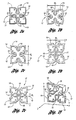
- FIG. 7a-7f an exemplary cell 12 of the surface support structure 10 of Figure 3 is illustrated.
- the cell 12 is illustrated with four upright walls as one non-limiting example of a cell 12. It should be understood that any combination of upright walls 14, 15 of any cell 12 of Figure 3 could be utilized and the upright walls 14 are for illustrative purposes. Of course, any suitable amount of upright walls 14 is contemplated within the scope of the disclosed embodiments.
- the cell 12 is illustrated under normal at rest conditions such that the cell 12 is not extended or contracted. Under normal conditions, the cell 12 has a perimeter P defined by the upright walls 14. In the illustrated embodiment, the recessed portions 16 formed in each upright wall 14 do not extend beyond the perimeter P of the cell 12. Although the recessed portions 16 are illustrated in each upright wall 14, the recessed portions 16 may be formed in only one or more of the upright walls 14, as desired.
- each cell 12 can be integrally formed with another cell 12 without interference between adjacent recessed portions 16, as illustrated in Figure 3 .
- the recessed portions 16 are orientated within corners of the upright walls 14 and extend within the perimeter P of the cell 12.
- any suitable orientation for the recessed portions 16 is contemplated within the scope of the disclosed embodiments.
- the cell 12 illustrated in Figure 7a is illustrated in two extended positions.
- the cell 12 is extended along the x-axis X
- the cell 12 is extended along the y-axis Y.
- the cell 12 is extended outward from a midpoint M x along the x-axis X.
- the cell 12 is extended outward from a midpoint M y along the y-axis Y.
- the cell 12 can be extended along the x-axis X and the y-axis Y simultaneously and as discuss below, the cell 12 may also move about the z-axis.
- the cell 12 of Figure 7a is illustrated in two contracted positions.
- the cell 12 is contracted along the x-axis X
- the cell 12 is contracted along the y-axis Y.
- the cell 12 is contracted outward from a midpoint M x along the x-axis X.
- the cell 12 is contracted outward from a midpoint M y along the y-axis Y.
- the cell 12 can be contracted and/or extended along the x-axis X and the y-axis Y simultaneously and as discuss below, the cell 12 may also move about the z-axis.
- the cell 12 shown in Figure 7a is depicted in an extended or rotated position.
- the cell 12 is rotated along the z-axis Z to illustrate that the cell 12 can adjust to various ground surfaces and various ground topography.
- the cell 12 can be rotated about the z-axis Z in a direction opposite to the direction illustrated. Additionally, one portion of the cell 12 may move about the z-axis in one direction while another portion of the cell 12 moves about the z-axis in another direction.
- the cell 12 is extended along the x-axis X and rotated in along the z-axis Z.
- the cell 12 is contracted along the x-axis X and rotated in along the z-axis Z.
- the cell 12 is extended along the y-axis Y and rotated in along the z-axis Z. In yet another embodiment, the cell 12 is contracted along the y-axis Y and rotated in along the z-axis Z.
- the recessed portions 16 allow the cell 12 to move/rotate about the z-axis Z in order for a local portion of the cell 12 to move. Since the cell 12 can have localized movement, the surface support structure 10 of Figures 1-6 , can also have localized movement within various portions of various cells 12 with expansion and/or contraction about x-axis X, the y-axis Y, and/or the z-axis Z and differing cells 12 having differing expansion and/or contraction.
- a surface support structure assembly 22 is illustrated having multiple surface support structures 10 that are joined together with fasteners 18.
- the fasteners 18 can be provided on outer upright walls 14 of the surface support structures 10 to join one surface support structure 10 to another surface support structure 10.
- one surface support structure 10 may be joined to multiple other surface support structures 10 so that the surface support structure assembly 22 can be built to accommodate various size requirements of various ground surfaces.
- the surface support structures 10 are formed with apertures 20 provided within outer upright walls 14.
- the apertures 20 are orientated to receive the fasteners 18 provided on adjacently provided surface support structures 10.
- the fasteners 18 can be inserted into the apertures 20 and retained within the apertures 20 to form the surface support structure assembly 22. Any suitable amount of fasteners 18 and/or apertures 20 is contemplated within the scope of the disclosed embodiments.
- recessed portions 16 allow movement of each cell 12 even proximate outer upright walls 14.
- the surface support structure assembly 22 has continuous flexibility that is not discontinued between the surface support structures 10 where joined together.
- the surface support structures 10 each have recessed portions 16 provided in each cell 12 to allow local movement within each cell 12.
- the local movement of each cell 12 can be along any of the x-axis, y-axis and the z-axis, as discussed above.
- the local movement of each cell 12 allows the surface support structure assembly 22 to be easily installed on various ground surfaces and can adapt to various ground topographies that may change over time.
- FIG. 9-11 an embodiment of a fastener 18 is illustrated on an upright wall 14 of a cell.
- An aperture 20 is provided on another upright wall 14 of the cell 12 and is sized to receive a fastener 18 from another cell 12.
- the fastener 18 may be tapered so that engagement between the fastener 18 and an aperture 20 is increased.
Landscapes
- Engineering & Computer Science (AREA)
- Architecture (AREA)
- Civil Engineering (AREA)
- Structural Engineering (AREA)
- Road Paving Structures (AREA)
- Apparatus Associated With Microorganisms And Enzymes (AREA)
Applications Claiming Priority (1)
| Application Number | Priority Date | Filing Date | Title |
|---|---|---|---|
| US12/264,425 US7950191B2 (en) | 2008-11-04 | 2008-11-04 | Continuous flexible support structure assembly |
Publications (2)
| Publication Number | Publication Date |
|---|---|
| EP2182116A2 true EP2182116A2 (de) | 2010-05-05 |
| EP2182116A3 EP2182116A3 (de) | 2014-09-03 |
Family
ID=41566215
Family Applications (1)
| Application Number | Title | Priority Date | Filing Date |
|---|---|---|---|
| EP20080169582 Withdrawn EP2182116A3 (de) | 2008-11-04 | 2008-11-20 | Endlose flexible Tragestrukturanordnung |
Country Status (2)
| Country | Link |
|---|---|
| US (1) | US7950191B2 (de) |
| EP (1) | EP2182116A3 (de) |
Families Citing this family (47)
| Publication number | Priority date | Publication date | Assignee | Title |
|---|---|---|---|---|
| US7748177B2 (en) | 2004-02-25 | 2010-07-06 | Connor Sport Court International, Inc. | Modular tile with controlled deflection |
| US8397466B2 (en) * | 2004-10-06 | 2013-03-19 | Connor Sport Court International, Llc | Tile with multiple-level surface |
| US8407951B2 (en) | 2004-10-06 | 2013-04-02 | Connor Sport Court International, Llc | Modular synthetic floor tile configured for enhanced performance |
| US8230654B2 (en) * | 2009-06-10 | 2012-07-31 | Comc, Llc | Medallion insert for modular flooring assemblies |
| EP2525881A4 (de) * | 2010-01-22 | 2015-09-09 | Connor Sport Court International Inc | Modulares unterbodensystem |
| US8505256B2 (en) | 2010-01-29 | 2013-08-13 | Connor Sport Court International, Llc | Synthetic floor tile having partially-compliant support structure |
| USD654747S1 (en) * | 2011-02-24 | 2012-02-28 | Acrefine Engineering Services, Ltd. | Isolation pad |
| USD690033S1 (en) * | 2012-03-29 | 2013-09-17 | Flint Trading, Inc. | Rotatable, homogenous ashlar preform for traffic patterns |
| USD690440S1 (en) * | 2012-03-29 | 2013-09-24 | Flint Trading, Inc. | Rotatable, homogenous stacked preform for traffic patterns |
| USD689202S1 (en) * | 2012-03-29 | 2013-09-03 | Flint Trading, Inc. | Rotatable, homogenous quarter round preform for traffic patterns |
| USD690441S1 (en) * | 2012-03-29 | 2013-09-24 | Flint Trading, Inc. | Rotatable, homogeneous courtyard preform for traffic patterns |
| USD689627S1 (en) * | 2012-03-29 | 2013-09-10 | Flint Trading, Inc. | Rotatable, homogeneous running bond preform for traffic patterns |
| USD690439S1 (en) * | 2012-03-29 | 2013-09-24 | Flint Trading, Inc. | Rotatable, homogeneous diagonal preform for traffic patterns |
| USD690032S1 (en) * | 2012-03-29 | 2013-09-17 | Flint Trading, Inc. | Rotatable, homogeneous herringbone preform for traffic patterns |
| USD690438S1 (en) * | 2012-03-29 | 2013-09-24 | Flint Trading, Inc. | Rotatable, homogenous plain weave preform for traffic patterns |
| USD713562S1 (en) * | 2012-08-29 | 2014-09-16 | Flint Trading, Inc. | Rotatable homogeneous quarter round clover adornment assembly for traffic patterns |
| USD713561S1 (en) * | 2012-08-29 | 2014-09-16 | Flint Trading, Inc. | Rotatable homogeneous quarter round star adornment assembly for traffic patterns |
| USD713067S1 (en) * | 2012-08-29 | 2014-09-09 | Flint Trading, Inc. | Rotatable homogeneous quarter round stacked wheel adornment assembly for traffic patterns |
| USD713564S1 (en) * | 2012-08-29 | 2014-09-16 | Flint Trading, Inc. | Rotatable homogeneous quarter round alternating inverted wavy adornment assembly for traffic patterns |
| USD713066S1 (en) * | 2012-08-29 | 2014-09-09 | Flint Trading, Inc. | Rotatable, homogeneous quarter round swirled wave adornment for traffic patterns |
| USD713062S1 (en) * | 2012-08-29 | 2014-09-09 | Flint Trading, Inc. | Rotatable homogeneous quarter round uniform adornment assembly for traffic patterns |
| USD713064S1 (en) * | 2012-08-29 | 2014-09-09 | Flint Trading, Inc. | Rotatable homogeneous quarter round stacked arch adornment assembly for traffic patterns |
| USD713063S1 (en) * | 2012-08-29 | 2014-09-09 | Flint Trading, Inc. | Rotatable homogeneous quarter round wheel adornment assembly for traffic patterns |
| USD713560S1 (en) * | 2012-08-29 | 2014-09-16 | Flint Trading, Inc. | Rotatable homogeneous quarter round scallop adornment assembly for traffic patterns |
| USD713065S1 (en) * | 2012-08-29 | 2014-09-09 | Flint Trading, Inc. | Rotatable homogeneous quarter round inverted wave adornment assembly for traffic patterns |
| USD713563S1 (en) * | 2012-08-29 | 2014-09-16 | Flint Trading, Inc. | Rotatable homogeneous quarter round translated wavy adornment assembly for traffic patterns |
| US9038342B2 (en) * | 2012-12-31 | 2015-05-26 | Playsafer Surfacing LLC a division Rubberecycle | Unitary safety surface tiles and associated structures |
| US9016018B2 (en) | 2013-01-22 | 2015-04-28 | Laticrete International, Inc. | Support plate for installing tile |
| US8807865B1 (en) * | 2013-03-15 | 2014-08-19 | Easy Grass, LLC | Light weight load-bearing platform |
| US8734049B1 (en) * | 2013-11-22 | 2014-05-27 | Barry J. Stiles | One piece water permeable paver |
| USD771837S1 (en) * | 2015-01-23 | 2016-11-15 | Mariestella Colon Astacio | Paving mat |
| US9908692B2 (en) * | 2015-05-06 | 2018-03-06 | ASFI Partners, L.P. | Multi-piece storage tank pad with separate connectors |
| USD972175S1 (en) | 2015-12-29 | 2022-12-06 | Airlite Plastics Co. | Permeable paver |
| US9670624B1 (en) | 2015-12-29 | 2017-06-06 | Stiles Manufacturing, LLC | Double walled earth grabbing water permeable modular paver |
| US9617698B1 (en) * | 2015-12-29 | 2017-04-11 | Stiles Manufacturing, LLC | Permeable paver and modular light system |
| US10072383B1 (en) | 2015-12-29 | 2018-09-11 | Stiles Manufacturing, LLC | Interlocking traffic tile for one piece water permeable paver |
| AU2017260598B2 (en) * | 2016-04-26 | 2022-09-22 | Redwood Plastics And Rubber Corp. | Apparatus for laying a paver |
| US20180099403A1 (en) * | 2016-10-10 | 2018-04-12 | Creative Plastic Concepts, Llc | Rail system for sawhorses |
| USD822122S1 (en) * | 2017-03-14 | 2018-07-03 | Guidecraft, Inc. | Set of building blocks |
| KR101769737B1 (ko) * | 2017-04-20 | 2017-08-18 | 박서영 | 일체형 조립 방식의 잔디보호매트 및 잔디보호매트의 시공 방법 |
| US10697130B2 (en) * | 2018-01-09 | 2020-06-30 | Signature Systems Group Llc | Modular flooring tiles and system |
| USD880730S1 (en) * | 2018-04-10 | 2020-04-07 | Dimoplast, S.A. De C.V. | Grid to build permeable floors |
| US10731303B2 (en) | 2018-10-05 | 2020-08-04 | Brentwood Industries, Inc. | Ground reinforcing structure and related method |
| US11332892B2 (en) | 2019-08-14 | 2022-05-17 | Omachron Intellectual Property Inc. | Patio blocks and method of providing a UV coating |
| US11499272B2 (en) | 2019-08-14 | 2022-11-15 | Omachron Intellectual Property Inc. | Patio blocks with edge blocks |
| US20210047788A1 (en) * | 2019-08-14 | 2021-02-18 | Omachron Intellectual Property Inc. | Patio blocks with interior drainage |
| RU2757724C1 (ru) * | 2021-01-29 | 2021-10-21 | Олег Михайлович Франко | Панель газонной решетки |
Family Cites Families (35)
| Publication number | Priority date | Publication date | Assignee | Title |
|---|---|---|---|---|
| US1722139A (en) * | 1928-01-18 | 1929-07-23 | Galassi Pasquale | Insert for floorings and pavements |
| US3310906A (en) * | 1965-07-22 | 1967-03-28 | Fowler Knobbe & Gambrell | Toy construction blocks and assembly |
| FR2268112B1 (de) * | 1974-04-18 | 1982-01-15 | Bibi Roubi Albert | |
| DE2553086A1 (de) * | 1975-11-26 | 1977-06-02 | Paul Ritter | Mittel zur bodenstabilisierung |
| CH606618A5 (de) * | 1976-12-01 | 1978-11-15 | Bruno Soland | |
| US4111585A (en) * | 1977-04-27 | 1978-09-05 | Mascaro Thomas C | Module and modular support for turfgrass and like areas |
| FR2428706A1 (fr) * | 1978-06-16 | 1980-01-11 | Berthomier Daniel | Revetement de sols, notamment pour terrains de tennis |
| US4372705A (en) * | 1980-11-18 | 1983-02-08 | Atkinson Francis S | Articulated erosion control system |
| US4440818A (en) * | 1983-03-30 | 1984-04-03 | Teknor Apex Company | Floor mat connector device |
| US4584221A (en) * | 1984-07-19 | 1986-04-22 | Sportforderung Peter Kung Ag | Floor covering assembly |
| US4671699A (en) * | 1986-06-09 | 1987-06-09 | Roach Edward F | Turf compatible paver system |
| US5250340A (en) * | 1990-08-31 | 1993-10-05 | Bohnhoff William W | Mat for stabilizing particulate materials |
| DK89291D0 (da) * | 1991-05-13 | 1991-05-13 | Frank Bentzon | Gulvbelaegningssystem med sammenkoblige fliseelementer, navnlig plastfliser |
| CN2144917Y (zh) * | 1992-12-09 | 1993-11-03 | 帅青园艺企业股份有限公司 | 蜂巢式植草砖 |
| DE9417815U1 (de) * | 1994-11-07 | 1995-01-05 | Kienle, Alexander, 86152 Augsburg | Gitterplatte zur Befestigung von natürlichem Grund |
| US5713175A (en) * | 1995-06-30 | 1998-02-03 | Mitchell; Steven Glenn | Protective flooring |
| DE19529473C1 (de) * | 1995-08-11 | 1996-08-22 | Wolfgang Weber | Mehrzweckbauteil mit Federelementen |
| US5787654A (en) * | 1995-09-21 | 1998-08-04 | Sport Court, Inc. | Isogrid tile |
| DE19616235A1 (de) * | 1996-04-15 | 1997-10-16 | Martin Hennings | Gitterplatte |
| GB9719198D0 (en) * | 1997-09-10 | 1997-11-12 | Milliken Denmark | Mat |
| AUPO997897A0 (en) * | 1997-10-23 | 1997-11-20 | Killen, Andrew | Flooring system |
| USD423123S (en) * | 1997-11-13 | 2000-04-18 | Hans Sassenberg | Plastic paver |
| US5950378A (en) * | 1997-12-22 | 1999-09-14 | Council; Walter S. | Composite modular floor tile |
| USD442704S1 (en) * | 1998-01-20 | 2001-05-22 | Sian Ghee Alan Lee | Decorative paving article |
| DE29816922U1 (de) * | 1998-09-16 | 1998-12-17 | Gamalczyk, Ryszard, Gorzwo | Rasengitterplatte |
| ES1046587Y (es) * | 2000-06-22 | 2001-06-01 | Vileda Iberica S A S En C | Felpudo modular. |
| DE20018841U1 (de) * | 2000-11-04 | 2001-02-08 | Seiß, Helmuth, 85080 Gaimersheim | Bodenbelag, bestehend aus einzeln zusammengefügten Platten |
| JP4464691B2 (ja) | 2004-01-13 | 2010-05-19 | アァルピィ東プラ株式会社 | パネル材の製造方法 |
| US7108454B2 (en) * | 2004-10-12 | 2006-09-19 | Airfield Systems, L.L.C. | Subsurface drainage system and drain structure therefor |
| US7201538B2 (en) * | 2004-12-03 | 2007-04-10 | Airfield Systems, L.L.C. | Subsurface drainage system and drain structure therefor |
| US7210876B2 (en) * | 2005-05-20 | 2007-05-01 | National Diversified Sales, Inc. | Rollable load bearing mat for turf areas |
| USD571024S1 (en) * | 2005-06-01 | 2008-06-10 | Alan Sian Ghee Lee | Grid structure for stabilization of grass, turf or particulate material |
| US7300224B2 (en) * | 2005-10-05 | 2007-11-27 | Slater William B | Support grid platform for supporting vehicles over ecologically sensitive terrain |
| KR100888037B1 (ko) | 2007-02-27 | 2009-03-09 | 임학순 | 천연잔디 블록 |
| US20080276557A1 (en) * | 2007-05-09 | 2008-11-13 | Antonio Rapaz | Construction panel |
-
2008
- 2008-11-04 US US12/264,425 patent/US7950191B2/en not_active Expired - Fee Related
- 2008-11-20 EP EP20080169582 patent/EP2182116A3/de not_active Withdrawn
Also Published As
| Publication number | Publication date |
|---|---|
| US20100109189A1 (en) | 2010-05-06 |
| US7950191B2 (en) | 2011-05-31 |
| EP2182116A3 (de) | 2014-09-03 |
Similar Documents
| Publication | Publication Date | Title |
|---|---|---|
| US7950191B2 (en) | Continuous flexible support structure assembly | |
| US8398332B2 (en) | Ground-reinforcing grid | |
| KR100527359B1 (ko) | 식물 재배 매트 | |
| US5073061A (en) | Industrial restraint edging system for segmented paving units | |
| EP1177347B1 (de) | Bodenbelag, decke und verfahren zum anlegen einer grünfläche | |
| EP2971360B1 (de) | Durchlässiges pflastersystem | |
| CN1050644C (zh) | 特别由混凝土制成的板形铺路砖 | |
| US20190345685A1 (en) | Ground Stabilization Grid | |
| US10400417B1 (en) | Ground stabilization grid | |
| EP3889353B1 (de) | Poroese verbundgitterplatten fuer boeden | |
| KR100954295B1 (ko) | 논두렁 구축용 블록 | |
| WO2011062585A1 (en) | Continuous flexible support structure assembly | |
| KR20150145681A (ko) | 멀티기능을 가진 보도블록 | |
| EP2385173A1 (de) | Straßenbelagsystem | |
| KR102448199B1 (ko) | 조립식 합성블록 | |
| KR100757453B1 (ko) | 연결.설치가 용이한 분리형 배수판 및 이를 이용한아파트단지 내의 도로 시공방법 | |
| US10280569B2 (en) | Golf course modular bunker paver blocks | |
| CN201109895Y (zh) | 人行步道砖固定装置 | |
| KR200283005Y1 (ko) | 도로 비탈면의 유실방지용 합성골판 콘크리트블록 구조 | |
| KR100626325B1 (ko) | 콘크리트 블록과 이 콘크리트 블록의 시공방법 | |
| KR200361060Y1 (ko) | 콘크리트 블록 | |
| JP4174410B2 (ja) | 組立式プランター | |
| JP3073346U (ja) | コンクリート製排水溝ブロック | |
| KR950001659Y1 (ko) | 조립식 논두렁 | |
| KR20170034070A (ko) | 투수 및 저류기능을 갖는 링크형 블록조립체 및 그 시공방법 |
Legal Events
| Date | Code | Title | Description |
|---|---|---|---|
| PUAI | Public reference made under article 153(3) epc to a published international application that has entered the european phase |
Free format text: ORIGINAL CODE: 0009012 |
|
| AK | Designated contracting states |
Kind code of ref document: A2 Designated state(s): AT BE BG CH CY CZ DE DK EE ES FI FR GB GR HR HU IE IS IT LI LT LU LV MC MT NL NO PL PT RO SE SI SK TR |
|
| AX | Request for extension of the european patent |
Extension state: AL BA MK RS |
|
| PUAL | Search report despatched |
Free format text: ORIGINAL CODE: 0009013 |
|
| AK | Designated contracting states |
Kind code of ref document: A3 Designated state(s): AT BE BG CH CY CZ DE DK EE ES FI FR GB GR HR HU IE IS IT LI LT LU LV MC MT NL NO PL PT RO SE SI SK TR |
|
| AX | Request for extension of the european patent |
Extension state: AL BA MK RS |
|
| RIC1 | Information provided on ipc code assigned before grant |
Ipc: E01C 9/00 20060101ALI20140725BHEP Ipc: E01C 5/20 20060101AFI20140725BHEP |
|
| AKY | No designation fees paid | ||
| AXX | Extension fees paid |
Extension state: MK Extension state: RS Extension state: BA Extension state: AL |
|
| REG | Reference to a national code |
Ref country code: DE Ref legal event code: R108 |
|
| REG | Reference to a national code |
Ref country code: DE Ref legal event code: R108 Effective date: 20150506 |
|
| STAA | Information on the status of an ep patent application or granted ep patent |
Free format text: STATUS: THE APPLICATION IS DEEMED TO BE WITHDRAWN |
|
| 18D | Application deemed to be withdrawn |
Effective date: 20150304 |