EP2182129B1 - Système d'îlots de plafond suspendu - Google Patents
Système d'îlots de plafond suspendu Download PDFInfo
- Publication number
- EP2182129B1 EP2182129B1 EP09174640A EP09174640A EP2182129B1 EP 2182129 B1 EP2182129 B1 EP 2182129B1 EP 09174640 A EP09174640 A EP 09174640A EP 09174640 A EP09174640 A EP 09174640A EP 2182129 B1 EP2182129 B1 EP 2182129B1
- Authority
- EP
- European Patent Office
- Prior art keywords
- clamping element
- flange
- clamping
- frame member
- profile
- Prior art date
- Legal status (The legal status is an assumption and is not a legal conclusion. Google has not performed a legal analysis and makes no representation as to the accuracy of the status listed.)
- Active
Links
Images


Classifications
-
- E—FIXED CONSTRUCTIONS
- E04—BUILDING
- E04B—GENERAL BUILDING CONSTRUCTIONS; WALLS, e.g. PARTITIONS; ROOFS; FLOORS; CEILINGS; INSULATION OR OTHER PROTECTION OF BUILDINGS
- E04B9/00—Ceilings; Construction of ceilings, e.g. false ceilings; Ceiling construction with regard to insulation
- E04B9/30—Ceilings; Construction of ceilings, e.g. false ceilings; Ceiling construction with regard to insulation characterised by edge details of the ceiling; e.g. securing to an adjacent wall
-
- E—FIXED CONSTRUCTIONS
- E04—BUILDING
- E04B—GENERAL BUILDING CONSTRUCTIONS; WALLS, e.g. PARTITIONS; ROOFS; FLOORS; CEILINGS; INSULATION OR OTHER PROTECTION OF BUILDINGS
- E04B9/00—Ceilings; Construction of ceilings, e.g. false ceilings; Ceiling construction with regard to insulation
- E04B9/06—Ceilings; Construction of ceilings, e.g. false ceilings; Ceiling construction with regard to insulation characterised by constructional features of the supporting construction, e.g. cross section or material of framework members
- E04B9/12—Connections between non-parallel members of the supporting construction
- E04B9/127—Connections between non-parallel members of the supporting construction one member being discontinuous and abutting against the other member
-
- E—FIXED CONSTRUCTIONS
- E04—BUILDING
- E04B—GENERAL BUILDING CONSTRUCTIONS; WALLS, e.g. PARTITIONS; ROOFS; FLOORS; CEILINGS; INSULATION OR OTHER PROTECTION OF BUILDINGS
- E04B9/00—Ceilings; Construction of ceilings, e.g. false ceilings; Ceiling construction with regard to insulation
- E04B9/18—Means for suspending the supporting construction
-
- E—FIXED CONSTRUCTIONS
- E04—BUILDING
- E04B—GENERAL BUILDING CONSTRUCTIONS; WALLS, e.g. PARTITIONS; ROOFS; FLOORS; CEILINGS; INSULATION OR OTHER PROTECTION OF BUILDINGS
- E04B9/00—Ceilings; Construction of ceilings, e.g. false ceilings; Ceiling construction with regard to insulation
- E04B9/34—Grid-like or open-work ceilings, e.g. lattice type box-like modules, acoustic baffles
Definitions
- the present invention relates to a suspendable ceiling island system
- a suspendable ceiling island system comprising at least one frame member for forming a frame at least partly delimiting a ceiling island comprising at least one ceiling tile
- the frame member comprising a longitudinally extending upright web with a first and second longitudinally extending profile flange mounted along opposite respective first and second longitudinal sides of the upright web and pointing away from the upright web from the respective first and second longitudinal side along an extending direction
- a clamping element comprising clamping means for mounting the clamping element to the frame member by clamping the clamping element in a clamping volume delimited by the first and the second profile flanges and the upright web such that an assembly of the frame member and the clamping element is formed, the clamping element when mounted to the frame member being substantially located in the clamping volume, according to the preamble of the first claim.
- EP0516330A2 describes a suspendable ceiling island system, according to the preamble of claim 1, comprising a frame with a plurality of longitudinal and transverse runners which form a suspension grid to support the edges of the ceiling tiles forming the island.
- the ceiling island is suspended to the existing building construction, by suspending the runners using conventional hangers.
- the end parts of the longitudinal and transverse runners are received in the inner volume of frame members, which run along the edges of the ceiling island to provide a finishing of the longitudinal and transverse edges of the ceiling island.
- Each frame member comprises a longitudinally extending upright web and a first and a second profile flange, which extend in longitudinal direction of the upright web and point perpendicularly away from opposite sides of the upright web.
- the edges of the first and second profile flanges are provided with respectively a first and second hemmed edge.
- the frame members are attached to the end parts of the runners, using a clamping element which substantially fits into the inner volume of the frame member delimited by the upright web and the first and second profile flanges.
- the clamping element comprises an upright side provided to run along the upright web of the frame member, a bottom flange provided to be clamped between the upright web and the second hemmed edge and a top flange provided with an upwards extending lip provided to clamp the top flange between the first hemmed edge and the upright web of the frame member.
- the top flange of the clamping element extends from the inner volume of the frame member, over at least part of the bead of the runner and is fastened to it.
- the ceiling island system described by EP0516330A2 necessarily includes runners, as they provide the support for the ceiling tiles, also for those tiles which run along the frame members.
- the runners are also indispensable for the suspension of the ceiling island.
- Runners therefore form an indispensible part of the ceiling island of EP0516330A2 .
- the physical properties and position in the ceiling island needs to be adapted to permit suspension of the ceiling island in each particular situation. It is however not always desired to include runners when designing a ceiling island, nor is it always desirable to adapt the physical properties and/or position of the runners to the suspension of the ceiling island.
- the suspendable ceiling island system comprises suspending means for suspending the frame, the suspending means extend from the clamping volume and the assembly of the frame member and the clamping element is provided to receive and support at least part of the ceiling tile.
- the suspending means extend from the clamping volume, sufficient room is left in the clamping volume for receiving at least part of a ceiling tile along at least part of at least one of its edges.
- the flanges of the frame member function as a support for at least a part of at least one edge of the ceiling tile.
- Part of the edge of the ceiling tile is received within the clamping element.
- part of the ceiling tile is directly supported by a flange of the frame member and part of the ceiling tile is supported by the assembly of the frame member and the clamping element. This support is achieved without having to install a runner to at least partly support the ceiling tile.
- the suspending means extend from the clamping member, the framed ceiling island can be suspended directly at the frame members without having to use runners to effectuate the suspension.
- the number of runners used in the ceiling island can be substantially reduced. This way the weight of the ceiling island as well as the material cost may be substantially reduced.
- the inventor has moreover found that the presence of the clamping element in the internal volume of the frame member provides a local reinforcement of the frame member. This way the strength of the frame members, their resistance to bending as well as the rigidity of the whole frame is improved. Strengthening the frame members is especially desired when frame members of considerable length are used and there is a risk of deflection due to its own weight.
- the clamping element is capable of receiving and supporting a ceiling tile along at least part of its edge and is provided with suspending means, the weight of the ceiling tile received by the clamping element is more directly carried by the clamping element.
- the frame member no longer needs to be provided to carry the total weight of the ceiling tile so that the load bearing capacity of the frame member can be decreased, leading, for example, to less stringent material properties of the frame member.
- the frame member can be more specifically adapted to align different clamping elements and/or the decorate the frame, etc.
- the suspending means extend from a part of the clamping element running along the first profile flange when the clamping element is mounted to the frame member.
- suspending means leave more distance between the suspending means and the ceiling tile, when provided in the frame.
- connecting the suspending means to means connecting the suspending means to for example a ceiling, such as for example a cord, can be performed more easily.
- the suspending means extend in an upward direction, as defined in the characterising part of claim 1.
- suspending means provide even more distance between the suspending means and the ceiling tile, when provided in the frame.
- Such suspending means therefore allow that the connecting means can be even more easily connected to the means connecting the suspending means to for example a ceiling.
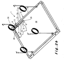
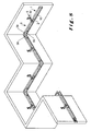
- the ceiling island shown in figure 2a is provided to be hung to a ceiling so that at least part of the ceiling is covered. This is however not critical for the invention and the ceiling island system 1 can also be provide to be mounted to a wall such that at least part of the wall is covered by the ceiling island.
- the frame 9 fully encloses the at least one tile 16 forming a circumferential frame 9, as shown in figure 2a and 2b .
- the sides of the suspendable ceiling island system 1 not enclosed by the frame 9 can be positioned adjacent to one or more sides of a wall.
- the dimensions of the ceiling island substantially depend on the dimensions of the frame 9. As a consequence its dimensions can be chosen independently from the dimensions of the ceiling, or wall as described above, to which the island ceiling system is suspendable and can be determined according to the desired physical properties of the ceiling island and the space covered by it related to for example specific heat insulating properties, sound proofing properties, preferred dimensions, etc.
- the ceiling island can therefore be mounted on specific locations where certain specific physical properties are requested.
- the circumferential frame 9 can for example be rectangular, square or triangular or can have any other form and shape depending upon the desired physical properties or depending upon esthetical considerations.
- the frame members 10 can have any form deemed appropriate by the person skilled in the art, but preferably they are straight.
- Preferred frame members 10 for constructing the circumferential frame 9 are profiles comprising a first longitudinally extending upright web 6 with a first profile flange 7, i.e. an upper profile flange 7, which extends in longitudinal direction of the first upright web 6 and which points away from the first upright web 6 from a first longitudinal side 17 in an extending direction.
- the first longitudinal side 17 extends along an upper edge of the first upright web 6.
- the preferred frame member 10 also comprises a second profile flange 8, i.e.
- a lower profile flange 8 which points away from a second longitudinal side 18 of the frame member 10 in the extending direction and preferably extends along a bottom side of the first upright web 6 opposite to the first longitudinal side 17.
- the first 7 and the second 8 profile flanges preferably run mainly parallel to each other so that the frame member 10 is mainly C-shaped and oblong with a longitudinal opening facing the tiles 16 and/or interior of the circumferential frame 10.
- the first 7 and/or second 8 profile flanges preferably extend along the entire length of the frame member 10 but can also extend along part of the frame member 10.
- the first profile flange 7 and the second profile flange 8 preferably extend perpendicular to the first upright web 6.
- the circumferential frame 9 may be composed of standard frame members 10 having a height of 40 mm between the first 7 and the second 8 profile flanges and the profile flanges having a width of 24 mm, written as 38 x 24 mm, but other sizes of for example 38 x 15 mm or others may suitably be used as well.
- the material thickness will usually be adapted taking into account the envisaged circumstances of use such as the dimensions of the frame 9 and the dimensions and weight of the ceiling tiles 16.
- Frame members 10 may have the same length as the length of the sides of the island ceiling system 1 or may be shorter or longer.
- the frame members 10 may be linked to each other in longitudinal direction of the frame members 10 or in a direction which is angled, with respect to the longitudinal direction of the frame members 10.
- Frame members 10 may at a corner, for example, run substantially perpendicular or any other angle depending on the shape of the frame 10.
- the frame members 10 may also all lie in one mutual plane. This is however not critical for the invention.
- Adjacent frame members 10 preferably are linked to each other to obtain the circumferential frame 9 using interconnecting pieces 30.
- the interconnecting pieces 30 preferably are also mainly C-shaped, but however also may be solid. Coupling in longitudinal and cross direction is achieved by using interconnecting pieces 30 which preferably have at least two end parts 28, 29, wherein a first end part 28 is positioned between an end part of the first 7 and second 8 profile flange of a first frame member 10 and a second end part 29 is positioned between an end part of the first 7 and second 8 profile flanges of a second frame member 10.
- the dimensions of the first 28 and second 29 end part of the interconnecting piece 30 preferably are such that the first 7 and second 8 profile flanges of the first and second adjacent frame members 10 exert a clamping action onto respectively the first 28 and second 29 end part of the interconnecting piece 30 in height direction thereof, thus fastening the first end part 28 of the interconnecting piece 30 to the first frame member 10 and the second end part 29 of the interconnecting piece 30 to the second frame member 10, therefore joining the two adjacent frame members 10 to each other.
- the height of the first 28 and/or second 29 end part of the interconnecting piece 30 can also be chosen so that the first 7 and second 8 profile flanges of the respective first and/or second frame member 10 are received in the respective first 28 and/or second 29 end part of the interconnecting piece 30 which exerts a clamping force onto the first 7 and second 8 profile flange of the respective first and/or second frame member 10.
- the first 28 and second 29 end part are positioned in line with each other.
- the first 28 and second 29 end part of the interconnecting piece 30 are positioned angled, e.g. perpendicular, with respect to each other.
- the interconnecting piece 30 and the frame member 10 preferably respectively comprise mutually co-operating interconnecting members which engage each other in a removable way, for example co-operating perforations and protrusions.
- the protrusions preferably are created by locally increasing the height of the material.
- the protrusions and/or perforations can have any form or shape deemed appropriate by the person skilled in the art such as rectangular, square, circular, oval, etc.
- the interconnecting piece 30 preferably can be compressed somewhat in height direction therefore making it easier to push the protrusions out of the perforations when separating the interconnecting piece 30 from the frame members 10.
- the frame member 10 can be compressed somewhat in height direction therefore making it easy to pull the perforations over the protrusions when separating the interconnecting piece 30 from the frame members 10.
- the frame members 10 can be made of any material deemed appropriate by the person skilled in the art such as for example plastic but preferably are made of metal.
- the interconnecting piece 30 preferably is made of plastic but any other material deemed appropriate by the person skilled in the art can be used, such as for example metal, wood, etc.
- the ceiling island system 1 also comprises a clamping element 2 comprising clamping means 3 for mounting the clamping element 2 to the frame member 10 by clamping the clamping element 2 between the first 7 and the second 8 profile flanges such that an assembly of the frame member 10 and the clamping element 2 is formed.
- the clamping element 2 when mounted to the frame member 10 is substantially located in a clamping volume 26 delimited by the upright web 6 and the first 7 and the second 8 profile flanges, as shown in figures 2a - 8 .
- the clamping element 2 comprises suspending means 5 for suspending the frame 9.
- the suspending means 5 extend out of the clamping volume 26 when the clamping element 2 is mounted to the frame member 10 although a substantial part of the clamping element 2, with respect to the suspending means 5, is located in the clamping volume 26.
- the assembly of the frame member 10 and the clamping element 2 is provided to receive and support at least part of the ceiling tile 16.
- the clamping means 3 preferably comprise at least one clamping element flange 11, i.e. a first upper clamping element flange 11, preferably at least two clamping element flanges 11, 12, provided to clamp the clamping element 2 in between the first 7 and second 8 profile flange.
- one clamping element flange 11, preferably at least two clamping element flanges 11, 12, are sufficient to clamp the clamping element 2 in between the first 7 and the second 8 profile flange
- the clamping means shown in figures 1 - 8 comprise three clamping element flanges 11, 12, 13: a first clamping element flange 11, a second clamping element flange 12, i.e. a second lower clamping element flange 12, and a third clamping element flange 13.
- the clamping element 2 can however also comprise more than three clamping element flanges 11, 12, 13 provided to clamp the clamping element 3 in between the first 7 and second 8 profile flange, for example: four, five six, seven eight, nine tine, eleven, etc....
- the clamping element flanges 11, 12, 13 can be made of any material deemed appropriate by the person skilled in the art.
- the material of the clamping element flanges 11, 12, 13 is metal, more preferable steel more preferable stainless steel.
- any other material can be used for the clamping element flanges 11, 12, 13 such as for example aluminium, for example extruded aluminium, plastic, etc.
- the different clamping element flanges 11, 12, 13 of the clamping means 3 can be interconnected in any way known to the person skilled in the art such as gluing, soldering, welding, bolting, stapling, riveting, nailing, etc.
- the different clamping element flanges 11, 12, 13 are preferably interconnected by folding lines. Although a different interconnection can be used between each pair of clamping element flanges 11, 12, 13, the different clamping element flanges 11, 12, 13 preferably are all interconnected by folding such that the different clamping element flanges 11, 12, 13 of the clamping means 3 can be folded from a single piece of material, preferably a piece of metal.
- Such clamping means 3 are for example shown in figure 1a - 1d .
- the third clamping element flange 13 preferably is provided to be positioned in the clamping volume 26 in an upright direction extending from the second profile flange 8 towards the first profile flange 7.
- the first clamping element flange 11 preferably extends from a first side 21 of the third flange 13 and is provided to extend towards the first profile flange 7 when the clamping element 2 is mounted to the frame member 10.
- the second clamping element flange 12 preferably extends from a second side 22 of the third flange 13 opposing the first side 21 of the third flange 13 and is provided to extend towards the second profile flange 8 when the clamping element 2 is mounted to the frame member 10.
- the first 11, second 12 and third 13 clamping element flanges are provided to clamp the clamping element 2 between the first 7 and the second 8 profile flanges such that an assembly of the frame member 10 and the clamping element 2 is formed.
- first 11 and the second 12 clamping element flange run substantially along the first 7 and the second 8 profile flange along the extending direction when clamping the clamping element 2 between the first 7 and/or second 8 profile flange
- the first 11 and second 12 clamping element flange can for example extend along a direction substantially opposing the extending direction, perpendicular to the extending direction, along an angle of substantially between 30 - 60° with the extending direction, for example substantially 45°.
- FIGS. 2 - 8 show that the first 11 and/or second 12 clamping element flange are provided to run substantially along the first 7 and/or second 8 profile flange when clamping the clamping element 2 between the first 7 and second 8 profile flange, this is not critical for the invention and the flange may also not run substantially along any one of the profile flanges 7, 8.
- FIGS. 7 - 8 show that the first 11 and/or the second 12 clamping element flange are provided to run substantially along the entire length of the first 7 and/or second 8 profile when clamping the clamping element 2 between the first 7 and second 8 profile flange, this is not critical for the invention and the flange may also run partially along any one of the profile flanges 7,8.
- FIGS. 2 - 8 show that the third clamping element flange 13 is provided to run substantially along the upright web 6 when clamping the clamping element 2 between the first 7 and second 8 profile flange, this is not critical for the invention and the third clamping element flange 13 can also be provided not to run substantially along the upright web 6.
- the third clamping element flange 13 can for example be provided not to run parallel to the upright web 6 and/or from a distance from the upright web 6.
- FIGS. 2 - 8 show that the third clamping element flange 13 is provided to run substantially along the entire length of the upright web 6 when clamping the clamping element 2 between the first 7 and second 8 profile flange, this is not critical for the invention and the flange may also run partially along the upright web 6.
- the inventor has found that when the first 11, the second 12 and/or the third 13 clamping element flange runs substantially along the respective first profile flange 7, second profile flange 8 and/or upright web 6 more room is provided to receive and support at least part of the ceiling tile 16.
- the inventor moreover found that when the first 11, the second 12 and/or the third 13 clamping element flange runs substantially along the respective first profile flange 7, second profile flange 8 and/or upright web 6 the strength of the frame member 10 is further improved.
- first 11, the second 12 and the third 13 clamping element flanges are provided to run substantially along the respective first profile flange 7, second profile flange 8 and upright web 6, since in such a case the clamping volume 26 can be almost entirely used for receiving and supporting the ceiling tile 16 such that an improved support of the ceiling tile 16 is achieved.
- the inventor moreover found that in such case the frame member 10 is even further reinforced.
- the suspending means 5 can be any means known to the person skilled in the art for suspending a ceiling island.
- the clamping element 2 can for example be provided with suspending means 5 provided for receiving a cord such as an opening, hook, etc.
- the suspending means 5 extend from a part of the clamping element 2 lying substantially along the first 7 or second 8 profile flange when the clamping element 2 is mounted to the frame member 10. More preferably, the suspending means 5 extend, more preferably extend substantially, in an upward direction. The inventor has found that when the suspending means 5 leave some distance between the suspending means 5 and the ceiling tile 16, when provided in the frame 9, as for example shown in figure 3a , connecting the suspending means 5 to the means connecting the suspending means to for example a ceiling, such as for example a cord, can be performed more easily.
- the inventor has moreover found that the distance between the suspending means 5 and the ceiling tile 16, when provided in the frame 9, also allows that when tiles 16 having a thickness extending along substantially the upright length of the upright web 6 of the frame member 10 are provided to the frame member 10, the suspending means 5 can still be used to suspend the frame 9, since the distance between the suspending means 5 and the ceiling tile 16 allows that the means for connecting the suspending means 5 to the ceiling can be attached to the suspending means 5.
- the distance between the suspending means 5 and the ceiling tile 16 allows that for example a cord is knotted to the suspending means 5.
- the suspending means 5 preferably extend in an upright direction from the end of the first clamping element flange 11, which end is situated opposite to the end of the first clamping element flange 11 that is connected to the third clamping element flange 13, such that the suspending means 5 protrudes above the plane defined by the first 7 profile flange.
- Figures 1 - 8 show that the suspending means 5 comprise a fourth clamping element flange 14.
- the clamping element flange 14 shown in figures 1 - 8 extends from the clamping means 3, more specifically from the first flange 11.
- the suspending means 5 comprise a fourth clamping element flange 14 which extends, preferably directly, from the end of the first clamping element flange 11, which end is situated opposite to the end of the first clamping element flange 11 that is connected to the third clamping element flange 13.
- the fourth clamping element flange 14 then protrudes above the plane defined by the first 7 profile flange.
- the fourth clamping element flange 14 preferably is similar to the first 11, second 12 and third 13 clamping element flanges and therefore preferably is made from metal, more preferably steel, even more preferably stainless steel. More preferably, similar to the first 11, second 12 and third 13 clamping element flanges, the fourth clamping element flange 14 is connected to the first clamping element flange 11 by a folding line.
- the fourth clamping element flange 14 preferably extends in an upright direction from the clamping means 3. This is however not critical for the invention and the fourth clamping element flange 14 can also extend in a downward direction or for example a direction running substantially along the extending direction.
- the fourth clamping element flange 14 can be provided with an opening provided for receiving an end part of the means connecting the suspending means 5 to the ceiling.
- the opening can for example be provided to receive an end part of a cord which can be knotted to the hole, a hook attached to the end part of a cord as shown in figure 2b and 3b or can be provided to be screwed to a piece provided thereto to an end part of the cord such as shown in figure 2a and 3a .
- the suspending means 5 comprise a fifth clamping element flange 15 extending preferably from the fourth clamping element flange 14 in a direction substantially along the extending direction when the clamping element 2 is mounted to the frame member 10.
- the fifth clamping element flange 15 preferably is similar to the first 11, second 12, third 13 and fourth 14 clamping element flanges and therefore preferably is made from metal, more preferably steel, even more preferably stainless steel. More preferably, similar to the first 11, second 12, third 13 and fourth 14 clamping element flanges, the fifth clamping element flange 15 is connected to the fourth clamping element flange 14 by a folding line.
- the fifth clamping element flange 15 can also extend in a downward direction or for example an upward direction.
- the fifth clamping element flange 15, as shown in figures 1 - 8 preferably is provided with an opening provided for receiving an end part of the means connecting the suspending means 5 to the ceiling.
- the opening can for example be provided to receive an end part of a cord which can be knotted to the hole, a hook attached to the end part of a cord as shown in figure 2b and 3b or can be provided to be screwed to a piece provided thereto to an end part of the cord such as shown in figure 2a and 3a .
- the ceiling island can be suspended to the ceiling using cords, as shown in figures 2a , 2b , 3a and 3b , other means can also be used to suspend the ceiling island to the ceiling such as for example bars, rods, etc.
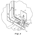
- FIG. 4 A first example is shown in figure 4 in which the suspending means 5 are provided to be clamped to the ceiling or wall of a room.
- the suspending means 5 are provided to be clamped to the ceiling or wall of a room.
- at least part of the suspending means 5, more specific the fifth flange 15 are clamped to the wall by pressing a mounting piece 31 onto the at least part of the suspending means 5, more specific the fifth flange 15.
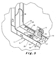
- the mounting piece 31 can however also be omitted, as shown in figure 5 , and the suspending means can be directly screwed, nailed, stapled, etc. to the wall or ceiling, as shown in figure 5 .
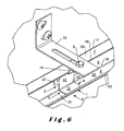
- the suspending means 5 however do not need to be connected directly to the wall or ceiling as shown in figure 5 , but can also be mounted to an intermediate piece 32, as shown in figure 6 .
- the intermediate piece 32 shown in figure 6 is provided to be mounted to the wall or ceiling and comprises an opening provided to bolt, nail, staple, etc. the suspending means 5 to it.
- the opening, as shown in figure 6 preferably is longitudinal such that the mounting location of the suspending means to the intermediate piece 32 can be adapted more easily while installing the ceiling island.
- Figures 7 and 8 show that the intermediate piece 32 allows a multitude of mounting arrangements of the ceiling island.
- Figure 7 for example show the application of the clamping element 2 in combination with the intermediate piece 32 to mount frames 10 to a wall having a curved surface.
- Figure 8 for example shows the application of the clamping element 2 in combination with the intermediate piece 32 to mount the frames 10 to an angled wall surface.
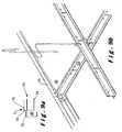
- Figure 9a and figure 9b show a different way to use the assembly of the frame member 10 and the clamping element 2.
- the clamping element 2, more specifically the suspending means 5 is connected to a T-shaped runner 33 as shown in figure 9b .
- Such a construction can be used to mount tiles 16 in the plane defined by the frame members 10 where the runner 33 is used to support the tiles 16 without the runner 33 being visible from below, known in the sector as an invisible mount.
- the tile 16 comprises a groove in which a supporting flange 34 of the runner 33 can be received, the depth of the flange preferably being substantially the width of the runner 33 so that two tiles 16 cover substantially the underside of the runner 33.
- the thickness of the tiles 16 below the groove when mounted to the runner 33 added to the height of the runner 33 substantially equals the sum of the height of the frame member 10 and the height along which the suspending means 5 extend to the mounting location of the top of the runner 33 with the suspending means 5, which often is the height of the fourth flange 14 measured along its upright direction.
- part of the tile 16 can extend in the clamping volume 26.
- Such a system provides a system in which tiles 16 can be mounted in an invisible mount using known runners 33.
- the runners 33 add to the strength of the system as they improve the fixation of the frame members 10 with respect to the remainder of the ceiling island system in which they are mounted.
- the height of the frame member 10 and the height of the runner 33 are substantially the same such that the height along which the suspending means 5 extend to the mounting location of the top of the runner 33 with the suspending means 5, which often is the height of the fourth flange 14 measured along its upright direction, is the same as the thickness of the tile 16 below the groove when mounted to the runner 33.
- Such a system allows to use frame members 10 and runners 33 to mount tiles 16 in a visible mount, in which the underside of the runners 33 is visible from below, as for example described in EP 1 811 098 A1 , and an invisible mount as discussed above using the same runners 33 and frame members 10. Therefore, the clamping element 2 adds to the possibilities to use runners 33 and frame members 10.
- the assembly of the frame member 10 and the clamping element 2 comprises positioning means 4 for positioning the clamping element 2 in the clamping volume between the first 7 and the second 8 profile flange along the extending direction when mounted to the frame member 10.
- the positioning means 4 shown in figure 3a and 3b comprise a second hemmed edge 20 provided on the second profile flange 8 of the frame member 10.
- the second hemmed edge 20 comprises a part of the second profile flange 8 which is folded to extend along the second profile flange 8 onto a second inner face 25 of the second profile flange 8 facing the clamping volume 26.
- the second hemmed edge 20 is provided to cooperate with the clamping means 3 to position the clamping element 2 in the clamping volume 26 between the first 7 and the second 8 profile flange along the extending direction when mounted to the frame member 10.
- Figures 3a , 3b and 6 for example show that the second clamping element flange 12 abuts against the second hemmed edge 20 limiting movement of the clamping element 2 out of the clamping volume 26 and therefore improving the positioning of the clamping element 2 in the clamping volume 26 when the clamping element 2 is mounted to the frame member 10.
- the second clamping element flange 12 is provided to mutually abut the second hemmed edge 20 at the second side 22 as well as the upright web 6 when the clamping element 2 is mounted to the frame member 10, as shown in figure 3a .
- the inventor has found that in such case the positioning of the clamping element 2 in the clamping volume 26 is even more improved since in addition to limiting the movement of the clamping element 2 out of the clamping volume 26 as described above, also movement of the clamping element 2 inside of the clamping volume 26 is limited such that the position of the second clamping element flange 12 in the clamping volume 26 becomes substantially fixed.
- the thickness of the second clamping element flange 12 does not substantially exceed the thickness of the second hemmed edge 20.
- the inventor has found that such a thickness of the second clamping element flange 12 substantially avoids fissures or openings between the ceiling tile 16 received and supported by the assembly of the frame member 10 and the clamping element 2 and the assembly of the frame member 10 and the clamping element 2 at the location of the clamping element 2. This way, the presence of an clamping element 2 does not substantially influence the look of the ceiling island.
- Figures 4 and 5 show that the positioning means 4 comprise a first hemmed edge 19 provided on the first profile flange 7 of the frame member 10.
- the first hemmed edge 19 comprises a part of the first profile flange 7 which is folded to extend along the first profile flange 7 onto a first inner face 24 of the first profile flange facing the clamping volume 26.
- the first hemmed edge 19 is provided to cooperate with the clamping means 3 to position the clamping element 2 in the clamping volume 26 between the first 7 and the second 8 profile flange along the extending direction when mounted to the frame member 10.
- Figure 4 and 5 show that the positioning means 4 comprise a connection member 23 extending towards the first profile flange 7 which is provided to be received between the first profile flange 7 and the first hemmed edge 19 of the frame member 10 when the clamping element 2 is mounted to the frame member 10.
- the inventor has found that the connection member 23 further limits the movement of the clamping element 2 out of the clamping volume 26 and therefore improves the positioning of the clamping element 2 in the clamping volume 26 when the clamping element 2 is mounted to the frame member 10.
- connection member 23 is provided on the clamping means 3, more preferably on the first clamping element flange 11.
- the connection member 23 preferably comprises a lip cut out off the first clamping element flange 11 and bent in an upward direction, as for example shown in figure 1 a.
- Any other connection member 23 is however also possible such as for example a separate piece mounted to the first clamping element flange 11, for example a metal piece, attached to the first profile flange 11 by soldering, welding, gluing, bolting, etc.
- the first flange 11 is provided to abut the upright web 6 at the first side 21 when the clamping element 2 is mounted to the frame member 10, as shown in figure 3a .
- the inventor has found that in such case the positioning of the clamping element 2 in the clamping volume 26 is improved since movement of the clamping element 2 inside of the clamping volume 26 is limited such that the position of the first clamping element flange 11 in the clamping volume 26 becomes substantially fixed.
- connection member 23 is received between the first profile flange 7 and the first hemmed edge 19 of the frame member 10 while the first clamping element flange 11 abuts the upright web at the first side 21 when the clamping element 2 is mounted to the frame member 10 such that the positioning of the first clamping element flange 11, and therefore of the clamping element 2, further improves.
- connection member 23 is provided to cooperate with the clamping means 3 when the clamping element 2 is mounted to the frame member 10 such that clamping of the clamping element 2 is improved.
- the connection member 23 has such a form and dimension that the connection member 23 snaps behind the first hemmed edge 19 when moving the clamping element 2 into the clamping volume 26 after placing the second clamping element flange 12 in an abutting position to the second hemmed edge 20.
- the connection member 23 has such a form and dimension that the first hemmed edge 19 snaps before the connection member 23 when moving the clamping element 2 into the clamping volume 26 after placing the second clamping element flange 12 in an abutting position to the second hemmed edge 20.
- the height with which the connection member 23 extends towards the first profile flange 7 is such that the first clamping element flange 11 runs substantially along the first profile flange 7, as described above.
- the clamping element 2 comprises fixing means 27 for fixing the position of the clamping element 2 along the longitudinal direction of the upright web 6 when the clamping element 2 is mounted to the frame member 10.
- the clamping element 2 can for example be bolted, nailed, screwed, welded, soldered, etc. to the frame member.
- Figures 2a , 3a , 4 and 5 for example show that the clamping element 2 is bolted to the frame member 10.
- the clamping element 2 thereto preferably is provided with at least one opening provided to receive the bolt, nail, staple, etc.
- the clamping element 2, more preferably the third clamping element flange 13, comprises at least one additional sixth clamping element flange in which an opening provided to receive the bolt, nail, staple etc. is provided.
- FIGS 2a , 3a , 4 and 5 show that two such sixth flanges are provided to the clamping element 2 each provided at an opposing upright side of the third clamping element flange 13.
- the number of sixth clamping element flanges, their position, location, form and dimension is however not critical for the invention and can be determined by the person skilled in the art.
- Figure 3a , 4 and 5 for example show that when the clamping element 2 is mounted to the frame member 10 adjacent to an interconnecting piece 30, the interconnecting piece 30 preferably is provided to receive the sixth clamping flange of the clamping element 2n such that the clamping element can be provided closer to the interconnecting element 30.
Landscapes
- Engineering & Computer Science (AREA)
- Architecture (AREA)
- Physics & Mathematics (AREA)
- Electromagnetism (AREA)
- Civil Engineering (AREA)
- Structural Engineering (AREA)
- Installation Of Indoor Wiring (AREA)
- Finishing Walls (AREA)
- Residential Or Office Buildings (AREA)
- Telephonic Communication Services (AREA)
- Building Environments (AREA)
- Supports For Pipes And Cables (AREA)
- Rod-Shaped Construction Members (AREA)
- Clamps And Clips (AREA)
Claims (11)
- Système d'îlots de plafond suspendu (1), comprenant:- au moins un élément de cadre (10) pour former un cadre (9) délimitant au moins en partie un îlot de plafond (1) comprenant au moins une dalle de plafond (16), l'élément de cadre (9) comprenant une âme verticale (6) s'étend longitudinalement avec une première (7) et une deuxième (8) aile de profilé s'étendant longitudinalement le long de premier (17) et deuxième (18) côtés longitudinaux respectifs de l'âme verticale (6) et s'écartant des premier (17) et deuxième (18) côtés longitudinaux respectifs de l'âme verticale (6) le long d'une direction d'extension,- un élément de serrage (2) comprenant des moyens de serrage (3) pour monter l'élément de serrage (2) sur l'élément de cadre (10) en serrant l'élément de serrage (2) dans un volume de serrage (26) délimité par la première (7) et la deuxième (8) aile de profilé et l'âme verticale (6) de sorte qu'un assemblage de l'élément de cadre (10) et de l'élément de serrage (2) est formé, l'élément de serrage (2) étant, quand il est monté sur l'élément de cadre (10), substantiellement situé dans le volume de serrage (26), l'élément de serrage (2) comprenant des moyens de suspension (5) pour suspendre le cadre (9), les moyens de suspension (5) s'étendant à partir du volume de serrage (26) quand l'élément de serrage (2) est monté sur l'élément de cadre (10) et l'assemblage de l'élément de cadre (10) et de l'élément de serrage (2) étant prévu pour recevoir et supporter au moins une partie de la dalle de plafond (16), les moyens de serrage (3) comprenant en outre une troisième aile (13) d'élément de serrage prévue pour être positionnée dans le volume de serrage (26) dans une direction verticale s'étendant de la deuxième aile (8) de profilé à la première aile (7) de profilé, une première aile (11) d'élément de serrage s'étendant à partir d'un premier côté (21) de la troisième aile (13) et prévue pour s'étendre vers la première aile (7) de profilé quand l'élément de serrage (2) est monté sur l'élément de cadre (10) et une deuxième aile (12) d'élément de serrage s'étendant à partir d'un deuxième côté (22) de la troisième aile (13) opposé au premier côté (21) de la troisième aile (13) et prévue pour s'étendre vers la deuxième aile (8) de profilé quand l'élément de serrage (2) est monté sur l'élément de cadre (10), les première (11), deuxième (12) et troisième (13) ailes d'élément de serrage étant prévues pour serrer l'élément de serrage (2) entre la première (7) et la deuxième (8) aile de profilé de sorte qu'un assemblage de l'élément de cadre (10) et de l'élément de serrage (2) est formé,caractérisé en ce que les moyens de suspensions (5) s'étendent dans une direction verticale à partir de l'extrémité de la première aile (11) d'élément de serrage, laquelle extrémité est située à l'opposé de l'extrémité de la première aile (11) d'élément de serrage qui est raccordée à la troisième aile (13) d'élément de serrage, de sorte que le moyen de suspension (5) fait saillie au-dessus du plan défini par la première (7) aile de profilé quand l'élément de serrage (2) est monté sur l'élément de cadre (10) pour former ledit îlot de plafond suspendu.
- Système d'îlots de plafond suspendu (1) tel que revendiqué dans la revendication 1, caractérisé en ce que les moyens de suspension (5) comprennent une quatrième aile (14) d'élément de serrage s'étendant directement à partir de l'extrémité de la première aile (11) d'élément de serrage, laquelle extrémité est située à l'opposé de l'extrémité de la première aile (11) d'élément de serrage qui est raccordée à la troisième aile (13) d'élément de serrage.
- Système d'îlots de plafond suspendu (1) tel que revendiqué dans l'une quelconque des revendications 1 - 2, caractérisé en ce que la première aile (11) d'élément de serrage court le long de la première aile (7) de profilé quand l'élément de serrage (2) est serré entre la première (7) et / ou deuxième (8) aile de profilé.
- Système d'îlots de plafond suspendu (1) tel que revendiqué dans l'une quelconque des revendications 1 - 3, caractérisé en ce que la première (11) et/ou deuxième (12) aile d'élément de serrage sont prévues pour courir sensiblement le long de la première (7) et / ou deuxième (8) aile de profilé quand l'élément de serrage (2) est serré entre la première (7) et la deuxième (8) aile de profilé.
- Système d'îlots de plafond suspendu (1) tel que revendiqué dans l'une quelconque des revendications 1 - 4, caractérisé en ce que la troisième aile (13) d'élément de serrage est prévue pour courir sensiblement le long de l'âme verticale (6) quand l'élément de serrage (2) est serré entre la première (7) et la deuxième (8) aile de profilé.
- Système d'îlots de plafond suspendu (1) tel que revendiqué dans l'une quelconque des revendications précédentes, caractérisé en ce que l'assemblage de l'élément de cadre (10) et de l'élément de serrage (2) comprend des moyens de positionnement (4) pour positionner l'élément de serrage (2) entre la première (7) et la deuxième (8) aile de profilé le long de la direction d'extension quand il est monté sur l'élément de cadre (10).
- Système d'îlots de plafond suspendu (1) tel que revendiqué dans la revendication 6, caractérisé en ce que les moyens de positionnement (4) servant à positionner l'élément de serrage dans le volume de serrage comprennent une deuxième bord ourlé (20) prévu sur la deuxième aile (8) de profilé de l'élément de cadre (10), le deuxième bord ourlé (20) comprenant une partie de la deuxième aile (8) de profilé qui est pliée pour s'étendre le long de la deuxième aile (8) de profilé sur une deuxième face intérieure (25) de la deuxième aile (8) de profilé faisant face au volume de serrage (26), le deuxième bord ourlé (20) étant prévu pour coopérer avec les moyens de serrage (3) pour positionner l'élément de serrage (2) dans le volume de serrage (26) le long de la direction d'extension quand il est monté sur l'élément de cadre (10).
- Système d'îlots de plafond suspendu (1) tel que revendiqué dans l'une quelconque des revendications 6 - 7, caractérisé en ce que les moyens de positionnement (4) servant à positionner l'élément de serrage dans le volume de serrage comprennent un premier bord ourlé (19) prévu sur la première aile (7) de profilé de l'élément de cadre (10), le premier bord ourlé (19) comprenant une partie de la première aile (7) de profilé qui est pliée pour s'étendre le long de la première aile (7) de profilé sur une première face intérieure (24) de la première aile de profilé faisant face au volume de serrage (26), le premier bord ourlé (19) étant prévu pour coopérer avec les moyens de serrage (3) pour positionner l'élément de serrage (2) dans le volume de serrage (26) le long de la direction d'extension quand il est monté sur l'élément de cadre (10).
- Système d'îlots de plafond suspendu (1) tel que revendiqué dans l'une quelconque des revendications 6 - 8, caractérisé en ce que les moyens de positionnement (4) comprennent un élément de raccordement (23) s'étendant depuis la première aile des moyens de serrage vers la première aile (7) de profilé et prévu pour être reçu entre la première aile (7) de profilé et le premier bord ourlé (19) de l'élément de cadre (10) quand l'élément de serrage (2) est monté sur l'élément de cadre (10).
- Système d'îlots de plafond suspendu (1) tel que revendiqué dans l'une quelconque des revendications 2 - 9, caractérisé en ce que les moyens de suspension (5) comprennent une cinquième aile (15) d'élément de serrage s'étendant depuis la quatrième aile (14) d'élément de serrage dans une direction sensiblement le long de la direction d'extension quand l'élément de serrage (2) est monté sur l'élément de cadre (10).
- Système d'îlots de plafond suspendu (1) tel que revendiqué dans l'une quelconque des revendications précédentes, caractérisé en ce que l'élément de serrage (2) comprend des moyens de fixation (27) pour fixer la position de l'élément de serrage (2) le long de la direction longitudinale de l'âme verticale (6) quand l'élément de serrage (2) est monté sur l'élément de cadre (10).
Priority Applications (2)
| Application Number | Priority Date | Filing Date | Title |
|---|---|---|---|
| PL09174640T PL2182129T3 (pl) | 2008-10-30 | 2009-10-30 | Wyspowy układ podwieszanego sufitu |
| EP09174640A EP2182129B1 (fr) | 2008-10-30 | 2009-10-30 | Système d'îlots de plafond suspendu |
Applications Claiming Priority (2)
| Application Number | Priority Date | Filing Date | Title |
|---|---|---|---|
| EP08167915A EP2182128A1 (fr) | 2008-10-30 | 2008-10-30 | Système d'îlots de plafond suspendu |
| EP09174640A EP2182129B1 (fr) | 2008-10-30 | 2009-10-30 | Système d'îlots de plafond suspendu |
Publications (2)
| Publication Number | Publication Date |
|---|---|
| EP2182129A1 EP2182129A1 (fr) | 2010-05-05 |
| EP2182129B1 true EP2182129B1 (fr) | 2011-12-14 |
Family
ID=40409844
Family Applications (2)
| Application Number | Title | Priority Date | Filing Date |
|---|---|---|---|
| EP08167915A Withdrawn EP2182128A1 (fr) | 2008-10-30 | 2008-10-30 | Système d'îlots de plafond suspendu |
| EP09174640A Active EP2182129B1 (fr) | 2008-10-30 | 2009-10-30 | Système d'îlots de plafond suspendu |
Family Applications Before (1)
| Application Number | Title | Priority Date | Filing Date |
|---|---|---|---|
| EP08167915A Withdrawn EP2182128A1 (fr) | 2008-10-30 | 2008-10-30 | Système d'îlots de plafond suspendu |
Country Status (6)
| Country | Link |
|---|---|
| EP (2) | EP2182128A1 (fr) |
| AT (1) | ATE537311T1 (fr) |
| DK (1) | DK2182129T3 (fr) |
| ES (1) | ES2377916T3 (fr) |
| PL (1) | PL2182129T3 (fr) |
| PT (1) | PT2182129E (fr) |
Families Citing this family (4)
| Publication number | Priority date | Publication date | Assignee | Title |
|---|---|---|---|---|
| CN102359219A (zh) * | 2011-10-28 | 2012-02-22 | 湖州民普厨卫科技有限公司 | 一种吊顶龙骨连接结构及其连接方法 |
| DK3088627T3 (da) * | 2015-04-29 | 2022-02-28 | Rockwool Int | Forsænket loftsystem til et forsænket loft, et forsænket loft og en fremgangsmåde til fremstilling af det forsænkede loft |
| CN112031248B (zh) * | 2020-04-30 | 2024-10-25 | 浙江德清康品集成家居股份有限公司 | 一种快搭式的吊顶 |
| SE544411C2 (en) * | 2020-09-17 | 2022-05-10 | Mitek Holdings Inc | Ceiling suspension bracket |
Family Cites Families (4)
| Publication number | Priority date | Publication date | Assignee | Title |
|---|---|---|---|---|
| US5201787A (en) | 1991-05-31 | 1993-04-13 | Usg Interiors, Inc. | Trim system for suspension ceilings |
| US5937605A (en) * | 1998-02-18 | 1999-08-17 | Usg Interiors, Inc. | Adjustable face trim clip for drywall suspension grid |
| US6298623B1 (en) * | 2000-06-09 | 2001-10-09 | Usg Interiors, Inc. | Adjustable trim strip system |
| ES2310394T3 (es) * | 2006-01-18 | 2009-01-01 | Chicago Metallic Continental | Sistema de islas para techos. |
-
2008
- 2008-10-30 EP EP08167915A patent/EP2182128A1/fr not_active Withdrawn
-
2009
- 2009-10-30 EP EP09174640A patent/EP2182129B1/fr active Active
- 2009-10-30 DK DK09174640.4T patent/DK2182129T3/da active
- 2009-10-30 PL PL09174640T patent/PL2182129T3/pl unknown
- 2009-10-30 ES ES09174640T patent/ES2377916T3/es active Active
- 2009-10-30 PT PT09174640T patent/PT2182129E/pt unknown
- 2009-10-30 AT AT09174640T patent/ATE537311T1/de active
Also Published As
| Publication number | Publication date |
|---|---|
| ATE537311T1 (de) | 2011-12-15 |
| EP2182129A1 (fr) | 2010-05-05 |
| PT2182129E (pt) | 2012-03-06 |
| EP2182128A1 (fr) | 2010-05-05 |
| PL2182129T3 (pl) | 2012-04-30 |
| DK2182129T3 (da) | 2012-03-05 |
| ES2377916T3 (es) | 2012-04-03 |
Similar Documents
| Publication | Publication Date | Title |
|---|---|---|
| EP2240649B1 (fr) | Appareil de blocage de cloison seche | |
| CA2912910C (fr) | Etrier a solive croisillonne | |
| WO1999046453B1 (fr) | Panneau terminal a largeur reglable | |
| EP1811098B1 (fr) | Système d'îlots de plafond | |
| AU2016270708B2 (en) | Ceiling mounting system and related method | |
| CN111502105B (zh) | 一种挂钩式吊顶安装结构 | |
| EP2182129B1 (fr) | Système d'îlots de plafond suspendu | |
| EP2472022A1 (fr) | Système de grille pour plafond suspendu | |
| FI74771B (fi) | Anordning vid ytbildande skiva. | |
| CN219528052U (zh) | 用于装配式隔墙的龙骨框架和龙骨连接装置及装配式隔墙 | |
| CN216305083U (zh) | 一种全卡扣装配式吊顶 | |
| CN218437725U (zh) | 一种龙骨挂件 | |
| JP3156192U (ja) | 天井板の支持構造 | |
| CN223081466U (zh) | 一种用于模块化吊顶体系内窗帘盒挡板快速制作的专用龙骨 | |
| JP2509436Y2 (ja) | 折版屋根の支持構造 | |
| CN113323229B (zh) | 一种全卡扣装配式吊顶及安装方法 | |
| CN218149178U (zh) | 一种模块化石膏板吊顶 | |
| JPH078685Y2 (ja) | 天井パネル用下地材の結合構造 | |
| JP3657182B2 (ja) | 出窓 | |
| JPH022805Y2 (fr) | ||
| RU49059U1 (ru) | Несущий узел для крепления фасадных облицовочных панелей (варианты) | |
| JPH09228538A (ja) | 鋼製天井フレームの連結金具 | |
| JPH0738511Y2 (ja) | 屋根パネルと小屋裏界壁パネルの支持金具 | |
| GB2479595A (en) | Hanger assembly with I-joist | |
| EP4022148A1 (fr) | Plaque de support et liaison de verrouillage |
Legal Events
| Date | Code | Title | Description |
|---|---|---|---|
| PUAI | Public reference made under article 153(3) epc to a published international application that has entered the european phase |
Free format text: ORIGINAL CODE: 0009012 |
|
| AK | Designated contracting states |
Kind code of ref document: A1 Designated state(s): AT BE BG CH CY CZ DE DK EE ES FI FR GB GR HR HU IE IS IT LI LT LU LV MC MK MT NL NO PL PT RO SE SI SK SM TR |
|
| AX | Request for extension of the european patent |
Extension state: AL BA RS |
|
| 17P | Request for examination filed |
Effective date: 20101105 |
|
| 17Q | First examination report despatched |
Effective date: 20101208 |
|
| R17C | First examination report despatched (corrected) |
Effective date: 20110111 |
|
| GRAP | Despatch of communication of intention to grant a patent |
Free format text: ORIGINAL CODE: EPIDOSNIGR1 |
|
| RIC1 | Information provided on ipc code assigned before grant |
Ipc: E04B 9/12 20060101ALI20110601BHEP Ipc: E04B 9/18 20060101ALI20110601BHEP Ipc: E04B 9/30 20060101AFI20110601BHEP |
|
| GRAS | Grant fee paid |
Free format text: ORIGINAL CODE: EPIDOSNIGR3 |
|
| GRAA | (expected) grant |
Free format text: ORIGINAL CODE: 0009210 |
|
| AK | Designated contracting states |
Kind code of ref document: B1 Designated state(s): AT BE BG CH CY CZ DE DK EE ES FI FR GB GR HR HU IE IS IT LI LT LU LV MC MK MT NL NO PL PT RO SE SI SK SM TR |
|
| REG | Reference to a national code |
Ref country code: GB Ref legal event code: FG4D |
|
| REG | Reference to a national code |
Ref country code: CH Ref legal event code: EP |
|
| REG | Reference to a national code |
Ref country code: IE Ref legal event code: FG4D |
|
| REG | Reference to a national code |
Ref country code: DK Ref legal event code: T3 |
|
| REG | Reference to a national code |
Ref country code: PT Ref legal event code: SC4A Free format text: AVAILABILITY OF NATIONAL TRANSLATION Effective date: 20120222 |
|
| REG | Reference to a national code |
Ref country code: DE Ref legal event code: R096 Ref document number: 602009004171 Country of ref document: DE Effective date: 20120315 |
|
| REG | Reference to a national code |
Ref country code: NL Ref legal event code: T3 |
|
| REG | Reference to a national code |
Ref country code: ES Ref legal event code: FG2A Ref document number: 2377916 Country of ref document: ES Kind code of ref document: T3 Effective date: 20120403 |
|
| REG | Reference to a national code |
Ref country code: NO Ref legal event code: T2 Effective date: 20111214 |
|
| PG25 | Lapsed in a contracting state [announced via postgrant information from national office to epo] |
Ref country code: LT Free format text: LAPSE BECAUSE OF FAILURE TO SUBMIT A TRANSLATION OF THE DESCRIPTION OR TO PAY THE FEE WITHIN THE PRESCRIBED TIME-LIMIT Effective date: 20111214 |
|
| REG | Reference to a national code |
Ref country code: PL Ref legal event code: T3 |
|
| REG | Reference to a national code |
Ref country code: SK Ref legal event code: T3 Ref document number: E 11197 Country of ref document: SK |
|
| LTIE | Lt: invalidation of european patent or patent extension |
Effective date: 20111214 |
|
| PG25 | Lapsed in a contracting state [announced via postgrant information from national office to epo] |
Ref country code: SI Free format text: LAPSE BECAUSE OF FAILURE TO SUBMIT A TRANSLATION OF THE DESCRIPTION OR TO PAY THE FEE WITHIN THE PRESCRIBED TIME-LIMIT Effective date: 20111214 Ref country code: SE Free format text: LAPSE BECAUSE OF FAILURE TO SUBMIT A TRANSLATION OF THE DESCRIPTION OR TO PAY THE FEE WITHIN THE PRESCRIBED TIME-LIMIT Effective date: 20111214 Ref country code: GR Free format text: LAPSE BECAUSE OF FAILURE TO SUBMIT A TRANSLATION OF THE DESCRIPTION OR TO PAY THE FEE WITHIN THE PRESCRIBED TIME-LIMIT Effective date: 20120315 Ref country code: HR Free format text: LAPSE BECAUSE OF FAILURE TO SUBMIT A TRANSLATION OF THE DESCRIPTION OR TO PAY THE FEE WITHIN THE PRESCRIBED TIME-LIMIT Effective date: 20111214 Ref country code: LV Free format text: LAPSE BECAUSE OF FAILURE TO SUBMIT A TRANSLATION OF THE DESCRIPTION OR TO PAY THE FEE WITHIN THE PRESCRIBED TIME-LIMIT Effective date: 20111214 |
|
| PG25 | Lapsed in a contracting state [announced via postgrant information from national office to epo] |
Ref country code: CY Free format text: LAPSE BECAUSE OF FAILURE TO SUBMIT A TRANSLATION OF THE DESCRIPTION OR TO PAY THE FEE WITHIN THE PRESCRIBED TIME-LIMIT Effective date: 20111214 |
|
| PG25 | Lapsed in a contracting state [announced via postgrant information from national office to epo] |
Ref country code: BG Free format text: LAPSE BECAUSE OF FAILURE TO SUBMIT A TRANSLATION OF THE DESCRIPTION OR TO PAY THE FEE WITHIN THE PRESCRIBED TIME-LIMIT Effective date: 20120314 Ref country code: EE Free format text: LAPSE BECAUSE OF FAILURE TO SUBMIT A TRANSLATION OF THE DESCRIPTION OR TO PAY THE FEE WITHIN THE PRESCRIBED TIME-LIMIT Effective date: 20111214 Ref country code: IS Free format text: LAPSE BECAUSE OF FAILURE TO SUBMIT A TRANSLATION OF THE DESCRIPTION OR TO PAY THE FEE WITHIN THE PRESCRIBED TIME-LIMIT Effective date: 20120414 |
|
| PG25 | Lapsed in a contracting state [announced via postgrant information from national office to epo] |
Ref country code: RO Free format text: LAPSE BECAUSE OF FAILURE TO SUBMIT A TRANSLATION OF THE DESCRIPTION OR TO PAY THE FEE WITHIN THE PRESCRIBED TIME-LIMIT Effective date: 20111214 |
|
| PLBE | No opposition filed within time limit |
Free format text: ORIGINAL CODE: 0009261 |
|
| STAA | Information on the status of an ep patent application or granted ep patent |
Free format text: STATUS: NO OPPOSITION FILED WITHIN TIME LIMIT |
|
| 26N | No opposition filed |
Effective date: 20120917 |
|
| REG | Reference to a national code |
Ref country code: DE Ref legal event code: R097 Ref document number: 602009004171 Country of ref document: DE Effective date: 20120917 |
|
| REG | Reference to a national code |
Ref country code: NL Ref legal event code: V1 Effective date: 20130501 |
|
| REG | Reference to a national code |
Ref country code: NO Ref legal event code: MMEP |
|
| PG25 | Lapsed in a contracting state [announced via postgrant information from national office to epo] |
Ref country code: MC Free format text: LAPSE BECAUSE OF NON-PAYMENT OF DUE FEES Effective date: 20121031 |
|
| REG | Reference to a national code |
Ref country code: DK Ref legal event code: EBP |
|
| PG25 | Lapsed in a contracting state [announced via postgrant information from national office to epo] |
Ref country code: FI Free format text: LAPSE BECAUSE OF FAILURE TO SUBMIT A TRANSLATION OF THE DESCRIPTION OR TO PAY THE FEE WITHIN THE PRESCRIBED TIME-LIMIT Effective date: 20111214 |
|
| REG | Reference to a national code |
Ref country code: SK Ref legal event code: MM4A Ref document number: E 11197 Country of ref document: SK Effective date: 20121030 |
|
| REG | Reference to a national code |
Ref country code: FR Ref legal event code: ST Effective date: 20130628 |
|
| PG25 | Lapsed in a contracting state [announced via postgrant information from national office to epo] |
Ref country code: SK Free format text: LAPSE BECAUSE OF NON-PAYMENT OF DUE FEES Effective date: 20121030 Ref country code: DE Free format text: LAPSE BECAUSE OF NON-PAYMENT OF DUE FEES Effective date: 20130501 Ref country code: NO Free format text: LAPSE BECAUSE OF NON-PAYMENT OF DUE FEES Effective date: 20121031 Ref country code: CZ Free format text: LAPSE BECAUSE OF NON-PAYMENT OF DUE FEES Effective date: 20121030 |
|
| REG | Reference to a national code |
Ref country code: IE Ref legal event code: MM4A |
|
| REG | Reference to a national code |
Ref country code: PT Ref legal event code: MM4A Free format text: LAPSE DUE TO NON-PAYMENT OF FEES Effective date: 20130730 |
|
| REG | Reference to a national code |
Ref country code: DE Ref legal event code: R119 Ref document number: 602009004171 Country of ref document: DE Effective date: 20130501 |
|
| PG25 | Lapsed in a contracting state [announced via postgrant information from national office to epo] |
Ref country code: FR Free format text: LAPSE BECAUSE OF NON-PAYMENT OF DUE FEES Effective date: 20121031 Ref country code: NL Free format text: LAPSE BECAUSE OF NON-PAYMENT OF DUE FEES Effective date: 20130501 |
|
| PG25 | Lapsed in a contracting state [announced via postgrant information from national office to epo] |
Ref country code: IE Free format text: LAPSE BECAUSE OF NON-PAYMENT OF DUE FEES Effective date: 20121030 Ref country code: DK Free format text: LAPSE BECAUSE OF NON-PAYMENT OF DUE FEES Effective date: 20121031 Ref country code: PT Free format text: LAPSE BECAUSE OF NON-PAYMENT OF DUE FEES Effective date: 20130730 |
|
| PG25 | Lapsed in a contracting state [announced via postgrant information from national office to epo] |
Ref country code: MT Free format text: LAPSE BECAUSE OF FAILURE TO SUBMIT A TRANSLATION OF THE DESCRIPTION OR TO PAY THE FEE WITHIN THE PRESCRIBED TIME-LIMIT Effective date: 20111214 |
|
| PG25 | Lapsed in a contracting state [announced via postgrant information from national office to epo] |
Ref country code: PL Free format text: LAPSE BECAUSE OF NON-PAYMENT OF DUE FEES Effective date: 20121030 |
|
| REG | Reference to a national code |
Ref country code: ES Ref legal event code: FD2A Effective date: 20140408 |
|
| PG25 | Lapsed in a contracting state [announced via postgrant information from national office to epo] |
Ref country code: TR Free format text: LAPSE BECAUSE OF FAILURE TO SUBMIT A TRANSLATION OF THE DESCRIPTION OR TO PAY THE FEE WITHIN THE PRESCRIBED TIME-LIMIT Effective date: 20111214 |
|
| PG25 | Lapsed in a contracting state [announced via postgrant information from national office to epo] |
Ref country code: ES Free format text: LAPSE BECAUSE OF NON-PAYMENT OF DUE FEES Effective date: 20121031 Ref country code: SM Free format text: LAPSE BECAUSE OF FAILURE TO SUBMIT A TRANSLATION OF THE DESCRIPTION OR TO PAY THE FEE WITHIN THE PRESCRIBED TIME-LIMIT Effective date: 20111214 Ref country code: LU Free format text: LAPSE BECAUSE OF NON-PAYMENT OF DUE FEES Effective date: 20121030 |
|
| PG25 | Lapsed in a contracting state [announced via postgrant information from national office to epo] |
Ref country code: HU Free format text: LAPSE BECAUSE OF FAILURE TO SUBMIT A TRANSLATION OF THE DESCRIPTION OR TO PAY THE FEE WITHIN THE PRESCRIBED TIME-LIMIT Effective date: 20091030 |
|
| PG25 | Lapsed in a contracting state [announced via postgrant information from national office to epo] |
Ref country code: MK Free format text: LAPSE BECAUSE OF FAILURE TO SUBMIT A TRANSLATION OF THE DESCRIPTION OR TO PAY THE FEE WITHIN THE PRESCRIBED TIME-LIMIT Effective date: 20111214 |
|
| REG | Reference to a national code |
Ref country code: CH Ref legal event code: PUE Owner name: ROCKWOOL INTERNATIONAL A/S, DK Free format text: FORMER OWNER: CHICAGO METALLIC CONTINENTAL, BE Ref country code: CH Ref legal event code: NV Representative=s name: GLN S.A., CH |
|
| REG | Reference to a national code |
Ref country code: CH Ref legal event code: PFA Owner name: ROCKWOOL INTERNATIONAL A/S, DK Free format text: FORMER OWNER: ROCKWOOL INTERNATIONAL A/S, DK |
|
| REG | Reference to a national code |
Ref country code: GB Ref legal event code: 732E Free format text: REGISTERED BETWEEN 20170305 AND 20170308 |
|
| REG | Reference to a national code |
Ref country code: BE Ref legal event code: PD Owner name: ROCKWOOL INTERNATIONAL A/S; DK Free format text: DETAILS ASSIGNMENT: CHANGE OF OWNER(S), CESSION; FORMER OWNER NAME: CHICAGO METALLIC CONTINENTAL Effective date: 20180206 |
|
| REG | Reference to a national code |
Ref country code: AT Ref legal event code: PC Ref document number: 537311 Country of ref document: AT Kind code of ref document: T Owner name: ROCKWOOL INTERNATIONAL A/S, DK Effective date: 20180611 |
|
| REG | Reference to a national code |
Ref country code: CH Ref legal event code: NV Representative=s name: BOVARD SA NEUCHATEL CONSEILS EN PROPRIETE INTE, CH |
|
| REG | Reference to a national code |
Ref country code: AT Ref legal event code: HC Ref document number: 537311 Country of ref document: AT Kind code of ref document: T Owner name: ROCKWOOL A/S, DK Effective date: 20230929 |
|
| REG | Reference to a national code |
Ref country code: BE Ref legal event code: PD Owner name: ROCKWOOL INTERNATIONAL A/S; DK Free format text: DETAILS ASSIGNMENT: CHANGE OF OWNER(S), OTHER; FORMER OWNER NAME: LUYS MARIE-JOSE Effective date: 20241212 Ref country code: BE Ref legal event code: HC Owner name: ROCKWOOL A/S; DK Free format text: DETAILS ASSIGNMENT: CHANGE OF OWNER(S), CHANGE OF OWNER(S) NAME; FORMER OWNER NAME: ROCKWOOL INTERNATIONAL A/S Effective date: 20241212 |
|
| REG | Reference to a national code |
Ref country code: CH Ref legal event code: U11 Free format text: ST27 STATUS EVENT CODE: U-0-0-U10-U11 (AS PROVIDED BY THE NATIONAL OFFICE) Effective date: 20251101 |
|
| PGFP | Annual fee paid to national office [announced via postgrant information from national office to epo] |
Ref country code: GB Payment date: 20251027 Year of fee payment: 17 |
|
| PGFP | Annual fee paid to national office [announced via postgrant information from national office to epo] |
Ref country code: AT Payment date: 20251029 Year of fee payment: 17 |
|
| PGFP | Annual fee paid to national office [announced via postgrant information from national office to epo] |
Ref country code: IT Payment date: 20251021 Year of fee payment: 17 |
|
| PGFP | Annual fee paid to national office [announced via postgrant information from national office to epo] |
Ref country code: BE Payment date: 20251027 Year of fee payment: 17 |
|
| PGFP | Annual fee paid to national office [announced via postgrant information from national office to epo] |
Ref country code: CH Payment date: 20251101 Year of fee payment: 17 |
|
| REG | Reference to a national code |
Ref country code: CH Ref legal event code: R18 Free format text: ST27 STATUS EVENT CODE: U-0-0-R10-R18 (AS PROVIDED BY THE NATIONAL OFFICE) Effective date: 20260209 |
|
| REG | Reference to a national code |
Ref country code: CH Ref legal event code: R18 Free format text: ST27 STATUS EVENT CODE: U-0-0-R10-R18 (AS PROVIDED BY THE NATIONAL OFFICE) Effective date: 20260320 |