EP2182172A1 - Turbomachine comprimante avec injection de fluide - Google Patents
Turbomachine comprimante avec injection de fluide Download PDFInfo
- Publication number
- EP2182172A1 EP2182172A1 EP10001422A EP10001422A EP2182172A1 EP 2182172 A1 EP2182172 A1 EP 2182172A1 EP 10001422 A EP10001422 A EP 10001422A EP 10001422 A EP10001422 A EP 10001422A EP 2182172 A1 EP2182172 A1 EP 2182172A1
- Authority
- EP
- European Patent Office
- Prior art keywords
- blade
- fluid
- rotor
- turbomachine according
- shoulder
- Prior art date
- Legal status (The legal status is an assumption and is not a legal conclusion. Google has not performed a legal analysis and makes no representation as to the accuracy of the status listed.)
- Granted
Links
Images


Classifications
-
- F—MECHANICAL ENGINEERING; LIGHTING; HEATING; WEAPONS; BLASTING
- F01—MACHINES OR ENGINES IN GENERAL; ENGINE PLANTS IN GENERAL; STEAM ENGINES
- F01D—NON-POSITIVE DISPLACEMENT MACHINES OR ENGINES, e.g. STEAM TURBINES
- F01D5/00—Blades; Blade-carrying members; Heating, heat-insulating, cooling or antivibration means on the blades or the members
- F01D5/12—Blades
- F01D5/14—Form or construction
- F01D5/20—Specially-shaped blade tips to seal space between tips and stator
-
- F—MECHANICAL ENGINEERING; LIGHTING; HEATING; WEAPONS; BLASTING
- F01—MACHINES OR ENGINES IN GENERAL; ENGINE PLANTS IN GENERAL; STEAM ENGINES
- F01D—NON-POSITIVE DISPLACEMENT MACHINES OR ENGINES, e.g. STEAM TURBINES
- F01D5/00—Blades; Blade-carrying members; Heating, heat-insulating, cooling or antivibration means on the blades or the members
- F01D5/12—Blades
- F01D5/14—Form or construction
- F01D5/141—Shape, i.e. outer, aerodynamic form
- F01D5/145—Means for influencing boundary layers or secondary circulations
-
- F—MECHANICAL ENGINEERING; LIGHTING; HEATING; WEAPONS; BLASTING
- F04—POSITIVE - DISPLACEMENT MACHINES FOR LIQUIDS; PUMPS FOR LIQUIDS OR ELASTIC FLUIDS
- F04D—NON-POSITIVE-DISPLACEMENT PUMPS
- F04D29/00—Details, component parts, or accessories
- F04D29/66—Combating cavitation, whirls, noise, vibration or the like; Balancing
- F04D29/68—Combating cavitation, whirls, noise, vibration or the like; Balancing by influencing boundary layers
- F04D29/681—Combating cavitation, whirls, noise, vibration or the like; Balancing by influencing boundary layers especially adapted for elastic fluid pumps
- F04D29/684—Combating cavitation, whirls, noise, vibration or the like; Balancing by influencing boundary layers especially adapted for elastic fluid pumps by fluid injection
-
- F—MECHANICAL ENGINEERING; LIGHTING; HEATING; WEAPONS; BLASTING
- F05—INDEXING SCHEMES RELATING TO ENGINES OR PUMPS IN VARIOUS SUBCLASSES OF CLASSES F01-F04
- F05D—INDEXING SCHEME FOR ASPECTS RELATING TO NON-POSITIVE-DISPLACEMENT MACHINES OR ENGINES, GAS-TURBINES OR JET-PROPULSION PLANTS
- F05D2270/00—Control
- F05D2270/01—Purpose of the control system
- F05D2270/10—Purpose of the control system to cope with, or avoid, compressor flow instabilities
- F05D2270/101—Compressor surge or stall
-
- F—MECHANICAL ENGINEERING; LIGHTING; HEATING; WEAPONS; BLASTING
- F05—INDEXING SCHEMES RELATING TO ENGINES OR PUMPS IN VARIOUS SUBCLASSES OF CLASSES F01-F04
- F05D—INDEXING SCHEME FOR ASPECTS RELATING TO NON-POSITIVE-DISPLACEMENT MACHINES OR ENGINES, GAS-TURBINES OR JET-PROPULSION PLANTS
- F05D2270/00—Control
- F05D2270/01—Purpose of the control system
- F05D2270/17—Purpose of the control system to control boundary layer
-
- Y—GENERAL TAGGING OF NEW TECHNOLOGICAL DEVELOPMENTS; GENERAL TAGGING OF CROSS-SECTIONAL TECHNOLOGIES SPANNING OVER SEVERAL SECTIONS OF THE IPC; TECHNICAL SUBJECTS COVERED BY FORMER USPC CROSS-REFERENCE ART COLLECTIONS [XRACs] AND DIGESTS
- Y02—TECHNOLOGIES OR APPLICATIONS FOR MITIGATION OR ADAPTATION AGAINST CLIMATE CHANGE
- Y02T—CLIMATE CHANGE MITIGATION TECHNOLOGIES RELATED TO TRANSPORTATION
- Y02T50/00—Aeronautics or air transport
- Y02T50/60—Efficient propulsion technologies, e.g. for aircraft
Definitions
- the present invention relates to fluid flow machines such as fans, compressors, pumps and fans, in both axial, semi-axial and radial designs.
- the working medium or fluid may be gaseous or liquid.
- the invention relates to a fluid power machine having at least one rotor, the rotor comprising a plurality of rotor blades secured to a rotating shaft.
- At least one stator may exist, the stator being provided with stationary stator blades.
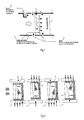
- the Fig.1 shows a schematic representation of the known from the prior art solutions. Shown are a schematic representation of a hub 11 and a housing 1, between which a fluid, as shown by the large arrow, flows from the left. Furthermore, a blade 2 is shown, which may be either a rotor 6 or stator 5 and whose visible area forms the suction side. As indicated by the arrows, there are designs for a local air supply at different locations of the fluid flow machine. For rotor and stator blading as well as flat experimental blade grids, it is known to inject fluid onto the blade suction side via slots 4 between the leading edge and about 60% of the tread depth in order to influence the two-dimensional profile boundary layer. The necessary fluid enters from a hollow, pressurized interior of the blade 2 in the main flow path. In alternative solutions, the blade profile is split to allow for supply by direct passage of the fluid from the blade pressure side to the blade suction side.
- the present invention has for its object to provide a fluid flow machine of the type mentioned, which has a very effective boundary layer influencing by targeted fluid supply and high efficiency while avoiding the prior art.
- the turbomachine according to the invention may comprise one or more stages each having a rotor and a stator; in some cases, the stage is formed only by a rotor.
- the rotor consists of a number of blades, which are connected to the rotating shaft of the fluid flow machine and deliver energy to the working fluid.
- the rotor can be designed with or without shroud on the outer blade end.
- the stator according to the invention consists of a number of fixed blades, which can be designed on the hub side as the housing side with a fixed or free blade end.
- the inventively provided rotor drum and the blading are usually surrounded by a housing, in others Cases, such as propellers and propellers, no housing exists.
- the turbomachine may have a stator in front of the first rotor, a so-called leading wheel.
- At least one stator or Vorleitrad may be rotatably mounted deviating from the immovable fixation in order to change the angle of attack.
- An adjustment is made for example by a spindle accessible from outside the annular channel.
- the turbomachine may have at least one row of adjustable rotors.
- this has two counter-rotating waves at Mehrstufmaschine, so that the rotor blade rows change the direction of rotation from stage to stage. There are no stators between successive rotors.
- the fluid flow machine can alternatively also have a bypass configuration such that the single-flow annular channel divides behind a specific row of blades into two concentric annular channels, which in turn each comprise at least one further row of blades.
- a fluid flow machine which comprises means for supplying fluid to at least one blade of a row of blades of the rotor and / or the stator at aerodynamically critical locations on trailing edge and edge surfaces (HRO).
- HRO trailing edge and edge surfaces
- the required openings on the wetted surfaces of the machine are arranged axially symmetrical, provided they outside the lying in the meridian view boundaries of the bladed space and are placed on the smooth annular channel wall in the main flow path projecting locations.
- the required openings are non-axisymmetric, provided they are outside the boundaries of the bladed space given in the meridian view and are flush with the smooth annular channel wall.
- the fluid flow machine on at least one blade of a rotor or stator series means for fluid supply, which are not selectively applied on the blade suction side in Meridianströmungsplatz, but over a defined area, and their Meridianerstreckung in meridianstromlinienorthogonaler direction at least one of the annular channel walls (hub or housing) decreases towards (suction side, intensity variable fluid supply SIFZ).
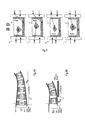
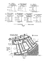
- the Fig. 2 shows a greatly simplified representation of the inventive solution to four differently configured rows of blades, each comprising a rotor 6 and a stator 7, which are provided with rotor blades 8 and stator blades 9.
- a housing or an outer shroud is reproduced in a greatly simplified representation.
- Reference numeral 11 denotes a rotor drum or an inner shroud.
- the selected view of the blade can represent both the suction side and the pressure side of the blade.
- a zone for suction-side intensity-variable fluid supply (SIFZ) is provided on rotors and stators.
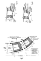
- the Fig. 4 shows four different configurations of the fluid flow machine according to the invention.
- the reference numeral 10 denotes a flow from left to right Ring channel, denoted by the reference numeral 13, the machine axis around which a rotor drum (hub) 11 rotates.
- a further rotor drum (hub) is provided at the in Figs. 5B and 5D shown embodiments.
- the rotors, stators and the pilot wheel are each in Fig. 5 labeled, it is shown in a schematic manner a blade.
- Fig. 5 shows the definition of the trailing edge and near-edge surfaces (HRO) according to the invention. It is in turn simplified a rotor 6 and a stator 7 are shown, which are arranged in the annular channel 10 between a housing 1 and a hub (rotor drum) 11.
- HRO trailing edge and near-edge surfaces
- the Fig. 8b shows a variant with an assembly consisting of a rotor drum, a plurality of rotating with the drum rotor blades with free outer ends, as well as a surrounding the rotating parts and stationary housing.
- the Fig. 8c shows an assembly consisting of a stationary outer housing, a plurality of stator blades connected to the outer housing, and one of the stator blades on the inner periphery worn shroud and a rotating within the stationary components rotor drum.
- the Fig. 8d shows an assembly consisting of a stationary outer housing, a plurality of stator blades connected to the outer housing with free inner ends and a rotating within the stationary components rotor drum.
- Fig. 8e For example, there is shown an assembly consisting of a stationary outer housing, a plurality of stator vanes connected to the outer housing with free inner ends, and an inner housing resting within the row of stator blades.
- the Fig. 8f shows an assembly consisting of a stationary inner housing, a plurality of stator blades connected to the inner housing with free outer ends, and an outer housing surrounding the Statorschaufelsch.
- the Fig. 8g illustrates an assembly, which consists of a stationary inner and outer housing, as well as several connected to the inner and outer housing stator blades.
- the guidance of the fluid to be supplied takes place via flow paths at the periphery of the annular channel 10 or within blades 8, 9 and their surrounding components.
- the fluid is supplied into the annular channel in the area of the relevant row of blades, either with free flow or with the aid of at least one throttle element 12 located in the flow path, which can be adjustable or adjustable.
- the supply of the fluid either takes place from a foreign source or is returned from locations of the fluid flow machine or the overall plant enclosing the fluid flow machine.
- the necessary elements of the flow path can be configured as a simple cavity, as an annular space, as a pipeline, as a channel, as a nozzle or as a diffuser of any cross-sectional shape and are summarized below under the term "chamber".
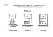
- Fig. 9 to 11 show different embodiments of the invention with configurations in which feed chambers (ZK), blade inner chambers (SK) and hub chambers (NK) are provided.
- each supply chamber ZK can communicate with and supply at least one blade inner chamber SK. If the blade has a fixed connection to the inner annular channel contour, then at least one chamber on or in the hub outside of the annular channel may exist as the last chamber member of the overall flow path designed for fluid supply (hub chamber NK) which communicates with at least one blade inner chamber SK and of this fluid receives.
- At least one supply chamber ZK can also exist on or in the hub outside the annular channel for supplying fluid to the hub.
- Feed chambers and hub chambers extend over all or part of the machine circumference.
- the feed chambers ZK serve the supply of fluid to the relevant blade row, wherein the blade inner chambers SK hub chambers chambers are tools to provide access to the relevant trailing edge and peripheral surfaces (HRO) of the relevant blade row.
- each supply chamber ZK can communicate with and supply at least one blade inner chamber SK.
- At least one chamber on or in the housing may exist as the last chamber member of the overall flow path designed for fluid supply (housing chamber GK), which communicates with at least one blade inner chamber SK and receives fluid from there.
- At least one supply chamber can also be present on or in the housing outside the annular channel for supplying fluid to the housing.
- the feed chambers and housing chambers extend over all or only parts of the circumference of the fluid power machine.
- the feed chambers serve to supply the fluid to the relevant blade row.
- the blade inner chambers and the housing chambers are aids to access to relevant Trailing edge and peripheral surfaces (HRO) in the area of the relevant blade row.
- HRO Trailing edge and peripheral surfaces
- the connection between the trailing edge and edge surfaces (HRO) and a supply chamber ZK, a blade inner chamber SK, a hub chamber NK or a housing chamber GK produces.
- the structural design of the fluid supply device takes place by means of mechanical, chemical or thermal material removal methods on the part forming the trailing edge and edge-near surface (HRO).
- the fluid supply device receives its limitations by combining at least two prepared individual components, which are joined together loosely or firmly.
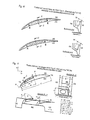
- the 15 to 20 show embodiments of the fluid supply device according to the invention on trailing edge and near-edge surfaces (HRO) of the type E, in which provided on the blade tip slots, round openings or functionally similar replacement elements are provided. Slots, round openings or replacement elements can be assigned to different blade chambers.
- HRO trailing edge and peripheral surfaces
- Other variants are in the Fig. 17 and 18 displayed.
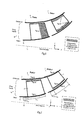
- the starting point A lies between the front edge VK and a tread depth of 30% of the chord length C.
- the end point E lies between the starting point A and a tread depth of 80% of the chord length C.
- the width W of the slot arrangement is variable and takes a maximum of depending on the tread depth current profile thickness D reduced by the heel foot width b (0 ⁇ W ⁇ Db).
- the slot has angular, chamfered or rounded surface edges. They have at the beginning and end of an angular shape or a round (slot-like) conclusion.
- HRO trailing edge and near-edge surfaces
- the entire configuration of the recesses extends from the starting point A to the end point E.
- the starting point A lies between the front edge VK and a tread depth of 30% of the chord length C.
- the end point E lies between the starting point A and a tread depth of 80% of the chord length C.
- the width W of the round opening is variable from position to position and assumes at most the width of the recess (0 ⁇ W ⁇ Db).
- the round opening has square, chamfered or rounded surface edges.
- a modified form occurs - with the same rules regarding the positioning and the course of the blade tip and the nature of the surface edges and orientation in the blade tip wall - in place of a round hole a row of holes or at least one slot whose beginning and end point is a polygonal shape or may have a round (slot-like) conclusion.
- turbomachine In the case of the turbomachine according to the invention, an unprecedented degree of boundary layer influencing is thus achieved. This is possible with different types of turbomachines such as fans, compressors, pumps and fans or even with propellers and propellers. Depending on the design variant, an aerodynamic load and a flow deflection are possible, which are up to 50% above the values achieved according to the current state of the art. For fixed power values of a fluid power machine can be while maintaining or improving the efficiency of up to 1% reduce the number of installed parts by about 30% compared to a conventional construction. The costs decrease by 10% to 15%. Using the new bucket concept in the compressor of an aircraft engine with approximately 25,000 pounds of thrust results in a reduction in specific fuel consumption of up to 0.5% and a weight saving of around 5%.
Landscapes
- Engineering & Computer Science (AREA)
- Mechanical Engineering (AREA)
- General Engineering & Computer Science (AREA)
- Physics & Mathematics (AREA)
- Fluid Mechanics (AREA)
- Structures Of Non-Positive Displacement Pumps (AREA)
Applications Claiming Priority (2)
| Application Number | Priority Date | Filing Date | Title |
|---|---|---|---|
| DE10355241A DE10355241A1 (de) | 2003-11-26 | 2003-11-26 | Strömungsarbeitsmaschine mit Fluidzufuhr |
| EP04024292A EP1536147B1 (fr) | 2003-11-26 | 2004-10-12 | Turbo compresseur ou pompe avec injection de fluide pour influencer la couche limite |
Related Parent Applications (1)
| Application Number | Title | Priority Date | Filing Date |
|---|---|---|---|
| EP04024292.7 Division | 2004-10-12 |
Publications (2)
| Publication Number | Publication Date |
|---|---|
| EP2182172A1 true EP2182172A1 (fr) | 2010-05-05 |
| EP2182172B1 EP2182172B1 (fr) | 2012-05-16 |
Family
ID=34442296
Family Applications (6)
| Application Number | Title | Priority Date | Filing Date |
|---|---|---|---|
| EP10006371A Withdrawn EP2226511A3 (fr) | 2003-11-26 | 2004-10-12 | Turbo compresseur ou pompe avec injection de fluide pour influencer la couche limite |
| EP10006367A Expired - Lifetime EP2226509B1 (fr) | 2003-11-26 | 2004-10-12 | Turbo compresseur ou pompe avec injection de fluide pour influencer la couche limite |
| EP04024292A Expired - Lifetime EP1536147B1 (fr) | 2003-11-26 | 2004-10-12 | Turbo compresseur ou pompe avec injection de fluide pour influencer la couche limite |
| EP10006368.4A Expired - Lifetime EP2226510B1 (fr) | 2003-11-26 | 2004-10-12 | Turbo compresseur ou pompe avec injection de fluide pour influencer la couche limite |
| EP10006370A Expired - Lifetime EP2228542B1 (fr) | 2003-11-26 | 2004-10-12 | Turbo compresseur ou pompe avec injection de fluide pour influencer la couche limite |
| EP10001422A Expired - Lifetime EP2182172B1 (fr) | 2003-11-26 | 2004-10-12 | Turbomachine comprimante avec injection de fluide |
Family Applications Before (5)
| Application Number | Title | Priority Date | Filing Date |
|---|---|---|---|
| EP10006371A Withdrawn EP2226511A3 (fr) | 2003-11-26 | 2004-10-12 | Turbo compresseur ou pompe avec injection de fluide pour influencer la couche limite |
| EP10006367A Expired - Lifetime EP2226509B1 (fr) | 2003-11-26 | 2004-10-12 | Turbo compresseur ou pompe avec injection de fluide pour influencer la couche limite |
| EP04024292A Expired - Lifetime EP1536147B1 (fr) | 2003-11-26 | 2004-10-12 | Turbo compresseur ou pompe avec injection de fluide pour influencer la couche limite |
| EP10006368.4A Expired - Lifetime EP2226510B1 (fr) | 2003-11-26 | 2004-10-12 | Turbo compresseur ou pompe avec injection de fluide pour influencer la couche limite |
| EP10006370A Expired - Lifetime EP2228542B1 (fr) | 2003-11-26 | 2004-10-12 | Turbo compresseur ou pompe avec injection de fluide pour influencer la couche limite |
Country Status (3)
| Country | Link |
|---|---|
| US (1) | US7387487B2 (fr) |
| EP (6) | EP2226511A3 (fr) |
| DE (2) | DE10355241A1 (fr) |
Families Citing this family (29)
| Publication number | Priority date | Publication date | Assignee | Title |
|---|---|---|---|---|
| DE102004055439A1 (de) * | 2004-11-17 | 2006-05-24 | Rolls-Royce Deutschland Ltd & Co Kg | Strömungsarbeitsmaschine mit dynamischer Strömungsbeeinflussung |
| DE102006048933A1 (de) * | 2006-10-17 | 2008-04-24 | Mtu Aero Engines Gmbh | Anordnung zur Strömungsbeeinflussung |
| DE102007029367A1 (de) * | 2007-06-26 | 2009-01-02 | Rolls-Royce Deutschland Ltd & Co Kg | Schaufel mit Tangentialstrahlerzeugung am Profil |
| DE102007037924A1 (de) * | 2007-08-10 | 2009-02-12 | Rolls-Royce Deutschland Ltd & Co Kg | Strömungsarbeitsmaschine mit Ringkanalwandausnehmung |
| FR2926322B1 (fr) * | 2008-01-10 | 2012-08-03 | Snecma | Aube bi-pale avec lames. |
| DE102008004834A1 (de) | 2008-01-17 | 2009-07-23 | Rolls-Royce Deutschland Ltd & Co Kg | Radialverdichter mit Abnahme und Rückführung von Luft am Gehäuse |
| EP2083148A3 (fr) * | 2008-01-23 | 2012-06-06 | Rolls-Royce Deutschland Ltd & Co KG | Turbine à gaz dotée d'un compresseur muni d'un revêtement de rodage et procédé de rodage des extrémités libres des aubes d'un compresseur de turbine à gaz |
| DE102008009604A1 (de) | 2008-02-15 | 2009-08-20 | Rolls-Royce Deutschland Ltd & Co Kg | Gehäusestrukturierung zum Stabilisieren der Strömung in einer Strömungsarbeitsmaschine |
| DE102008011644A1 (de) * | 2008-02-28 | 2009-09-03 | Rolls-Royce Deutschland Ltd & Co Kg | Gehäusestrukturierung für Axialverdichter im Nabenbereich |
| DE102008015207A1 (de) * | 2008-03-20 | 2009-09-24 | Rolls-Royce Deutschland Ltd & Co Kg | Fluid-Injektor-Düse |
| DE102008031982A1 (de) * | 2008-07-07 | 2010-01-14 | Rolls-Royce Deutschland Ltd & Co Kg | Strömungsarbeitsmaschine mit Nut an einem Laufspalt eines Schaufelendes |
| DE102008037154A1 (de) | 2008-08-08 | 2010-02-11 | Rolls-Royce Deutschland Ltd & Co Kg | Strömungsarbeitsmaschine |
| DE102008052409A1 (de) | 2008-10-21 | 2010-04-22 | Rolls-Royce Deutschland Ltd & Co Kg | Strömungsarbeitsmaschine mit saugseitennaher Randenergetisierung |
| DE102008060424A1 (de) | 2008-12-04 | 2010-06-10 | Rolls-Royce Deutschland Ltd & Co Kg | Strömungsmaschine mit Seitenwand-Grenzschicht-Barriere |
| EP2202385A1 (fr) * | 2008-12-24 | 2010-06-30 | Techspace Aero S.A. | Traitement de carter de compresseur de turbomachine consistant en une rainure circulaire décrivant une ondulation en vue de contrôler les tourbillons de tête d'aubes |
| US20110116934A1 (en) * | 2009-11-16 | 2011-05-19 | Meng Sen Y | Pumping element design |
| FR2961564B1 (fr) | 2010-06-17 | 2016-03-04 | Snecma | Compresseur et turbomachine a rendement optimise |
| JP2015048716A (ja) * | 2013-08-30 | 2015-03-16 | 株式会社東芝 | 蒸気タービン |
| GB2531029B (en) * | 2014-10-07 | 2020-11-18 | Cummins Ltd | Compressor and turbocharger |
| US9995166B2 (en) * | 2014-11-21 | 2018-06-12 | General Electric Company | Turbomachine including a vane and method of assembling such turbomachine |
| EP3037674A1 (fr) * | 2014-12-22 | 2016-06-29 | Alstom Technology Ltd | Moteur et procédé de fonctionnement dudit moteur |
| JP6694950B2 (ja) * | 2016-03-30 | 2020-05-20 | 三菱重工エンジン&ターボチャージャ株式会社 | 可変容量型ターボチャージャ |
| JP6603971B2 (ja) | 2016-08-09 | 2019-11-13 | 三菱重工コンプレッサ株式会社 | 蒸気タービン |
| EP3296573A1 (fr) * | 2016-09-20 | 2018-03-21 | Siemens Aktiengesellschaft | Technique de contrôle du décrochage tournant dans un compresseur de moteur à turbine à gaz |
| US10823197B2 (en) * | 2016-12-20 | 2020-11-03 | Pratt & Whitney Canada Corp. | Vane diffuser and method for controlling a compressor having same |
| DE102024131827A1 (de) * | 2024-10-31 | 2026-04-30 | KSB SE & Co. KGaA | Kreiselpumpe mit einem Laufrad |
| DE102024131828A1 (de) * | 2024-10-31 | 2026-04-30 | KSB SE & Co. KGaA | Kreiselpumpe mit einer Leitvorrichtung |
| DE102024131807A1 (de) * | 2024-10-31 | 2026-04-30 | KSB SE & Co. KGaA | Kreiselpumpe mit einer Leitvorrichtung |
| DE102024131806A1 (de) * | 2024-10-31 | 2026-04-30 | KSB SE & Co. KGaA | Kreiselpumpe mit einem Laufrad |
Citations (8)
| Publication number | Priority date | Publication date | Assignee | Title |
|---|---|---|---|---|
| FR1002324A (fr) | 1946-09-09 | 1952-03-05 | S. A. | Perfectionnements apportés aux turbo-machines à aubages, notamment aux compresseurs axiaux |
| DE2405050A1 (de) | 1974-02-02 | 1975-08-07 | Motoren Turbinen Union | Laufschaufeln fuer turbomaschinen |
| GB2158160A (en) | 1984-04-27 | 1985-11-06 | Gen Electric | A tip seal for bladed rotors |
| DE3850681T2 (de) | 1987-02-06 | 1995-03-09 | Wolfgang P Weinhold | Rotorblatt. |
| US5403158A (en) * | 1993-12-23 | 1995-04-04 | United Technologies Corporation | Aerodynamic tip sealing for rotor blades |
| US5476364A (en) * | 1992-10-27 | 1995-12-19 | United Technologies Corporation | Tip seal and anti-contamination for turbine blades |
| US5480284A (en) | 1993-12-20 | 1996-01-02 | General Electric Company | Self bleeding rotor blade |
| DE4003802A1 (de) * | 1988-08-24 | 1998-01-15 | United Technologies Corp | Spaltregulierung für die Turbine eines Gasturbinentriebwerks |
Family Cites Families (66)
| Publication number | Priority date | Publication date | Assignee | Title |
|---|---|---|---|---|
| GB479427A (en) * | 1935-05-31 | 1938-01-31 | Gyoergy Jendrassik | Improvements in rotary compressors |
| US2314572A (en) * | 1938-12-07 | 1943-03-23 | Herman E Chitz | Turboengine |
| DE889506C (de) | 1940-09-25 | 1953-09-10 | Versuchsanstalt Fuer Luftfahrt | Stroemungsmaschine mit Grenzschichtabsaugung |
| CH275562A (fr) * | 1946-01-04 | 1951-05-31 | Rateau Societe Anonyme Soc | Machine centrifuge. |
| US2555576A (en) * | 1946-05-07 | 1951-06-05 | Buffalo Forge Co | Axial flow fan |
| GB619722A (en) | 1946-12-20 | 1949-03-14 | English Electric Co Ltd | Improvements in and relating to boundary layer control in fluid conduits |
| US2870957A (en) | 1947-12-26 | 1959-01-27 | Edward A Stalker | Compressors |
| FR1066689A (fr) * | 1951-11-21 | 1954-06-09 | Westinghouse Electric Corp | Compresseur axial |
| CH316898A (de) * | 1952-09-11 | 1956-10-31 | Maschf Augsburg Nuernberg Ag | Beschaufelung für axial durchströmte Kreiselradmaschinen |
| US2933238A (en) * | 1954-06-24 | 1960-04-19 | Edward A Stalker | Axial flow compressors incorporating boundary layer control |
| GB792343A (en) * | 1954-10-06 | 1958-03-26 | Power Jets Res & Dev Ltd | Improvements in or relating to multi-stage aerofoil-bladed compressors |
| DE1106027B (de) * | 1955-07-18 | 1961-05-04 | Power Jets Res & Dev Ltd | Axialverdichter, dessen Lauf- und/oder Leitschaufeln mit einem Deckband versehen sind |
| GB799675A (en) | 1955-10-13 | 1958-08-13 | Bristol Aeroengines Ltd | Improvements in or relating to axial flow gas compressors and turbines |
| GB843979A (en) * | 1957-03-01 | 1960-08-10 | Westinghouse Electric Corp | Improvements in or relating to centrifugal fan rotors embodying airfoil blades |
| US3009630A (en) * | 1957-05-10 | 1961-11-21 | Konink Maschinenfabriek Gebr S | Axial flow fans |
| FR1318602A (fr) * | 1959-08-01 | 1963-02-22 | Procédé pour influencer la circulation d'un fluide, notamment dans des pompes centrifuges, et dispositif pour la réalisation de ce procédé | |
| FR1263010A (fr) * | 1960-07-21 | 1961-06-05 | M A N Turbomotoren G M B H | Procédé et dispositif pour modifier, dans les machines à écoulement de flaide, la déviation donnée par une grille d'aubes |
| US3066912A (en) | 1961-03-28 | 1962-12-04 | Gen Electric | Turbine erosion protective device |
| CH404069A (de) * | 1962-06-29 | 1965-12-15 | Licentia Gmbh | Strömungskanal, insbesondere Arbeitsmittelströmungskanal eines Turbokompressors |
| GB1085565A (en) * | 1963-06-27 | 1967-10-04 | Colchester Woods | Mixed flow fans |
| CH437614A (de) * | 1963-07-02 | 1967-11-30 | Moravec Zdenek | Strömungsmaschine mit verminderter Geräuscherzeugung |
| GB987625A (en) | 1963-10-14 | 1965-03-31 | Rolls Royce | Improvements in or relating to axial flow compressors, for example for aircraft gas turbine engines |
| US3237850A (en) * | 1964-08-24 | 1966-03-01 | Borg Warner | Axial flow fan with boundary layer control |
| DE1301432B (de) * | 1965-12-16 | 1969-08-21 | Bbc Brown Boveri & Cie | Anordnung zur Vergroesserung des stabilen Arbeitsbereiches von ein- und mehrstufigenAxialverdichtern, Geblaesen, Ventilatoren und Pumpen mittels Grenzschichtbeseitigung |
| US3572960A (en) | 1969-01-02 | 1971-03-30 | Gen Electric | Reduction of sound in gas turbine engines |
| DE1938132A1 (de) | 1969-07-26 | 1971-01-28 | Daimler Benz Ag | Leitschaufeln von Axialverdichtern |
| FR2166494A5 (fr) * | 1971-12-27 | 1973-08-17 | Onera (Off Nat Aerospatiale) | |
| US3934410A (en) * | 1972-09-15 | 1976-01-27 | The United States Of America As Represented By The Secretary Of The Navy | Quiet shrouded circulation control propeller |
| FR2248732A5 (fr) | 1973-10-23 | 1975-05-16 | Onera (Off Nat Aerospatiale) | |
| DE2458709C3 (de) * | 1973-12-11 | 1978-10-12 | Electricite De France Service National, Paris | Axialgebläse |
| US4131389A (en) * | 1975-11-28 | 1978-12-26 | The Garrett Corporation | Centrifugal compressor with improved range |
| US4155680A (en) | 1977-02-14 | 1979-05-22 | General Electric Company | Compressor protection means |
| CA1182399A (fr) * | 1979-09-10 | 1985-02-12 | Sergei K. Ivanov | Appareil de propulsion pour vehicule sur coussin d'air |
| FR2491549B1 (fr) | 1980-10-08 | 1985-07-05 | Snecma | Dispositif de refroidissement d'une turbine a gaz, par prelevement d'air au niveau du compresseur |
| DE3407945A1 (de) | 1984-03-03 | 1985-09-05 | MTU Motoren- und Turbinen-Union München GmbH, 8000 München | Verfahren und mittel zur vermeidung der entstehung von titanfeuer |
| US4863348A (en) * | 1987-02-06 | 1989-09-05 | Weinhold Wolfgang P | Blade, especially a rotor blade |
| US5059093A (en) | 1990-06-07 | 1991-10-22 | United Technologies Corporation | Compressor bleed port |
| US5203162A (en) | 1990-09-12 | 1993-04-20 | United Technologies Corporation | Compressor bleed manifold for a gas turbine engine |
| FR2666846B1 (fr) * | 1990-09-13 | 1992-10-16 | Alsthom Gec | Grille d'aubes pour turbomachine munie de fentes d'aspiration dans le plafond et/ou dans le plancher et turbomachine comportant ces grilles. |
| JPH04132899A (ja) | 1990-09-25 | 1992-05-07 | Mitsubishi Heavy Ind Ltd | 軸流送風機 |
| DE69204861T2 (de) | 1991-01-30 | 1996-05-23 | United Technologies Corp | Ventilatorgehäuse mit Rezirculationskanälen. |
| US5327716A (en) | 1992-06-10 | 1994-07-12 | General Electric Company | System and method for tailoring rotor tip bleed air |
| US5690473A (en) | 1992-08-25 | 1997-11-25 | General Electric Company | Turbine blade having transpiration strip cooling and method of manufacture |
| JPH06207558A (ja) * | 1993-01-11 | 1994-07-26 | Ishikawajima Harima Heavy Ind Co Ltd | エンジン用ファンの作動安定化装置 |
| JP3491342B2 (ja) * | 1994-06-27 | 2004-01-26 | 松下電工株式会社 | 軸流ファン |
| DE4438184C1 (de) * | 1994-10-26 | 1996-04-11 | Behr Gmbh & Co | Axiallüfter für den Kühler einer Verbrennungskraftmaschine |
| US5562404A (en) | 1994-12-23 | 1996-10-08 | United Technologies Corporation | Vaned passage hub treatment for cantilever stator vanes |
| US5607284A (en) | 1994-12-29 | 1997-03-04 | United Technologies Corporation | Baffled passage casing treatment for compressor blades |
| JP3816150B2 (ja) * | 1995-07-18 | 2006-08-30 | 株式会社荏原製作所 | 遠心流体機械 |
| US5762034A (en) | 1996-01-16 | 1998-06-09 | Board Of Trustees Operating Michigan State University | Cooling fan shroud |
| DE19632207A1 (de) * | 1996-08-09 | 1998-02-12 | Bmw Rolls Royce Gmbh | Verfahren zur Verhinderung der laminaren Grenzschicht-Ablösung an Turbomaschinen-Schaufeln |
| US6109868A (en) | 1998-12-07 | 2000-08-29 | General Electric Company | Reduced-length high flow interstage air extraction |
| US6574965B1 (en) | 1998-12-23 | 2003-06-10 | United Technologies Corporation | Rotor tip bleed in gas turbine engines |
| US6203269B1 (en) * | 1999-02-25 | 2001-03-20 | United Technologies Corporation | Centrifugal air flow control |
| US6302640B1 (en) | 1999-11-10 | 2001-10-16 | Alliedsignal Inc. | Axial fan skip-stall |
| GB0001399D0 (en) * | 2000-01-22 | 2000-03-08 | Rolls Royce Plc | An aerofoil for an axial flow turbomachine |
| US6334753B1 (en) | 2000-07-31 | 2002-01-01 | United Technologies Corporation | Streamlined bodies with counter-flow fluid injection |
| DE10135003C1 (de) | 2001-07-18 | 2002-10-02 | Mtu Aero Engines Gmbh | Verdichtergehäusestruktur |
| US6585479B2 (en) | 2001-08-14 | 2003-07-01 | United Technologies Corporation | Casing treatment for compressors |
| US6663346B2 (en) | 2002-01-17 | 2003-12-16 | United Technologies Corporation | Compressor stator inner diameter platform bleed system |
| DE10233032A1 (de) | 2002-07-20 | 2004-01-29 | Rolls-Royce Deutschland Ltd & Co Kg | Strömungsarbeitsmaschine mit integriertem Fluidzirkulationssystem |
| DE10330084B4 (de) | 2002-08-23 | 2010-06-10 | Mtu Aero Engines Gmbh | Rezirkulationsstruktur für Turboverdichter |
| CA2496543C (fr) | 2002-08-23 | 2010-08-10 | Mtu Aero Engines Gmbh | Structure de recirculation d'un turbocompresseur |
| US7097414B2 (en) | 2003-12-16 | 2006-08-29 | Pratt & Whitney Rocketdyne, Inc. | Inducer tip vortex suppressor |
| GB2413158B (en) | 2004-04-13 | 2006-08-16 | Rolls Royce Plc | Flow control arrangement |
| DE102004030597A1 (de) | 2004-06-24 | 2006-01-26 | Rolls-Royce Deutschland Ltd & Co Kg | Strömungsarbeitsmaschine mit Aussenradstrahlerzeugung am Stator |
-
2003
- 2003-11-26 DE DE10355241A patent/DE10355241A1/de not_active Withdrawn
-
2004
- 2004-10-12 EP EP10006371A patent/EP2226511A3/fr not_active Withdrawn
- 2004-10-12 EP EP10006367A patent/EP2226509B1/fr not_active Expired - Lifetime
- 2004-10-12 DE DE502004011970T patent/DE502004011970D1/de not_active Expired - Lifetime
- 2004-10-12 EP EP04024292A patent/EP1536147B1/fr not_active Expired - Lifetime
- 2004-10-12 EP EP10006368.4A patent/EP2226510B1/fr not_active Expired - Lifetime
- 2004-10-12 EP EP10006370A patent/EP2228542B1/fr not_active Expired - Lifetime
- 2004-10-12 EP EP10001422A patent/EP2182172B1/fr not_active Expired - Lifetime
- 2004-11-26 US US10/996,601 patent/US7387487B2/en not_active Expired - Fee Related
Patent Citations (8)
| Publication number | Priority date | Publication date | Assignee | Title |
|---|---|---|---|---|
| FR1002324A (fr) | 1946-09-09 | 1952-03-05 | S. A. | Perfectionnements apportés aux turbo-machines à aubages, notamment aux compresseurs axiaux |
| DE2405050A1 (de) | 1974-02-02 | 1975-08-07 | Motoren Turbinen Union | Laufschaufeln fuer turbomaschinen |
| GB2158160A (en) | 1984-04-27 | 1985-11-06 | Gen Electric | A tip seal for bladed rotors |
| DE3850681T2 (de) | 1987-02-06 | 1995-03-09 | Wolfgang P Weinhold | Rotorblatt. |
| DE4003802A1 (de) * | 1988-08-24 | 1998-01-15 | United Technologies Corp | Spaltregulierung für die Turbine eines Gasturbinentriebwerks |
| US5476364A (en) * | 1992-10-27 | 1995-12-19 | United Technologies Corporation | Tip seal and anti-contamination for turbine blades |
| US5480284A (en) | 1993-12-20 | 1996-01-02 | General Electric Company | Self bleeding rotor blade |
| US5403158A (en) * | 1993-12-23 | 1995-04-04 | United Technologies Corporation | Aerodynamic tip sealing for rotor blades |
Also Published As
| Publication number | Publication date |
|---|---|
| EP1536147A3 (fr) | 2008-04-09 |
| EP2226511A3 (fr) | 2011-06-15 |
| EP2228542B1 (fr) | 2012-05-16 |
| EP2226509A3 (fr) | 2011-06-08 |
| EP1536147A2 (fr) | 2005-06-01 |
| EP2226509B1 (fr) | 2012-07-25 |
| DE502004011970D1 (de) | 2011-01-20 |
| US7387487B2 (en) | 2008-06-17 |
| EP2226509A2 (fr) | 2010-09-08 |
| EP2226510B1 (fr) | 2013-08-28 |
| US20050141990A1 (en) | 2005-06-30 |
| DE10355241A1 (de) | 2005-06-30 |
| EP2182172B1 (fr) | 2012-05-16 |
| EP1536147B1 (fr) | 2010-12-08 |
| EP2226510A2 (fr) | 2010-09-08 |
| EP2228542A1 (fr) | 2010-09-15 |
| EP2226510A3 (fr) | 2011-06-15 |
| EP2226511A2 (fr) | 2010-09-08 |
Similar Documents
| Publication | Publication Date | Title |
|---|---|---|
| EP2182172B1 (fr) | Turbomachine comprimante avec injection de fluide | |
| EP2249043B1 (fr) | Compresseur ou pompe avec extraction de fluide | |
| EP1609999B1 (fr) | Turbo machine | |
| EP1659293B1 (fr) | Turbomachine | |
| EP2138727B1 (fr) | Bande de recouvrement d'aube dotée d'un passage | |
| EP2194232B1 (fr) | Turbomachine dotée d'une barrière à couche frontière sur la paroi latérale | |
| EP2108784B1 (fr) | Turbomachine dotée d'un composant d'injecteur de fluide | |
| EP1382855B1 (fr) | Turbomachine avec système de recirculation de fluide intégré | |
| EP2003292B1 (fr) | Machine de travail fluidique avec virole d'aube dotée d'un rebord | |
| EP2009239A2 (fr) | Aube dotée d'une production de jets tangentiels sur le profil | |
| EP2180193B1 (fr) | Turbomachine dotée d'un moyen pour énergiser des bords proches du côté aspirant | |
| EP2025945A2 (fr) | Machine de traitement des écoulements dotée d'un creux de paroi de canal de ceinture | |
| EP2151582A2 (fr) | Machine de traitement des écoulements | |
| EP1632662B1 (fr) | Turbomachine avec soutirage | |
| EP1998049A2 (fr) | Aube de machine de travail d'écoulement doté d'une conception à plusieurs profiles | |
| EP1637697B1 (fr) | Passage d'une machine à écoulement avec intervalle axial ayant une concentration inférieure à 1 | |
| EP1512490B1 (fr) | Procédé de réparation d'une aube de turbomachine | |
| EP1953340B1 (fr) | Machine de traitement des écoulements et aube de rotor d'une machine de traitement des écoulements | |
| WO2021110191A1 (fr) | Support d'étanchéité conçu pour une turbomachine comportant des ouvertures de type fentes dans le corps d'étanchéité |
Legal Events
| Date | Code | Title | Description |
|---|---|---|---|
| PUAI | Public reference made under article 153(3) epc to a published international application that has entered the european phase |
Free format text: ORIGINAL CODE: 0009012 |
|
| 17P | Request for examination filed |
Effective date: 20100211 |
|
| AC | Divisional application: reference to earlier application |
Ref document number: 1536147 Country of ref document: EP Kind code of ref document: P |
|
| AK | Designated contracting states |
Kind code of ref document: A1 Designated state(s): DE FR GB |
|
| 17Q | First examination report despatched |
Effective date: 20110518 |
|
| GRAP | Despatch of communication of intention to grant a patent |
Free format text: ORIGINAL CODE: EPIDOSNIGR1 |
|
| RIC1 | Information provided on ipc code assigned before grant |
Ipc: F01D 5/14 20060101ALN20111115BHEP Ipc: F04D 29/68 20060101ALN20111115BHEP Ipc: F01D 11/10 20060101AFI20111115BHEP Ipc: F01D 5/20 20060101ALI20111115BHEP |
|
| GRAS | Grant fee paid |
Free format text: ORIGINAL CODE: EPIDOSNIGR3 |
|
| GRAA | (expected) grant |
Free format text: ORIGINAL CODE: 0009210 |
|
| AC | Divisional application: reference to earlier application |
Ref document number: 1536147 Country of ref document: EP Kind code of ref document: P |
|
| AK | Designated contracting states |
Kind code of ref document: B1 Designated state(s): DE FR GB |
|
| REG | Reference to a national code |
Ref country code: GB Ref legal event code: FG4D Free format text: NOT ENGLISH |
|
| REG | Reference to a national code |
Ref country code: DE Ref legal event code: R096 Ref document number: 502004013512 Country of ref document: DE Effective date: 20120712 |
|
| PLBE | No opposition filed within time limit |
Free format text: ORIGINAL CODE: 0009261 |
|
| STAA | Information on the status of an ep patent application or granted ep patent |
Free format text: STATUS: NO OPPOSITION FILED WITHIN TIME LIMIT |
|
| 26N | No opposition filed |
Effective date: 20130219 |
|
| REG | Reference to a national code |
Ref country code: DE Ref legal event code: R097 Ref document number: 502004013512 Country of ref document: DE Effective date: 20130219 |
|
| REG | Reference to a national code |
Ref country code: FR Ref legal event code: PLFP Year of fee payment: 12 |
|
| REG | Reference to a national code |
Ref country code: FR Ref legal event code: PLFP Year of fee payment: 13 |
|
| PGFP | Annual fee paid to national office [announced via postgrant information from national office to epo] |
Ref country code: GB Payment date: 20161027 Year of fee payment: 13 Ref country code: FR Payment date: 20161025 Year of fee payment: 13 Ref country code: DE Payment date: 20161027 Year of fee payment: 13 |
|
| REG | Reference to a national code |
Ref country code: DE Ref legal event code: R119 Ref document number: 502004013512 Country of ref document: DE |
|
| GBPC | Gb: european patent ceased through non-payment of renewal fee |
Effective date: 20171012 |
|
| REG | Reference to a national code |
Ref country code: FR Ref legal event code: ST Effective date: 20180629 |
|
| PG25 | Lapsed in a contracting state [announced via postgrant information from national office to epo] |
Ref country code: DE Free format text: LAPSE BECAUSE OF NON-PAYMENT OF DUE FEES Effective date: 20180501 Ref country code: GB Free format text: LAPSE BECAUSE OF NON-PAYMENT OF DUE FEES Effective date: 20171012 |
|
| PG25 | Lapsed in a contracting state [announced via postgrant information from national office to epo] |
Ref country code: FR Free format text: LAPSE BECAUSE OF NON-PAYMENT OF DUE FEES Effective date: 20171031 |