EP2182176A2 - Cône d'entrée pour un moteur d'avion - Google Patents
Cône d'entrée pour un moteur d'avion Download PDFInfo
- Publication number
- EP2182176A2 EP2182176A2 EP09172753A EP09172753A EP2182176A2 EP 2182176 A2 EP2182176 A2 EP 2182176A2 EP 09172753 A EP09172753 A EP 09172753A EP 09172753 A EP09172753 A EP 09172753A EP 2182176 A2 EP2182176 A2 EP 2182176A2
- Authority
- EP
- European Patent Office
- Prior art keywords
- cone
- hub
- max
- propeller
- hub cone
- Prior art date
- Legal status (The legal status is an assumption and is not a legal conclusion. Google has not performed a legal analysis and makes no representation as to the accuracy of the status listed.)
- Withdrawn
Links
- 101100129500 Caenorhabditis elegans max-2 gene Proteins 0.000 claims description 3
- 239000000446 fuel Substances 0.000 description 2
- 238000000926 separation method Methods 0.000 description 2
- 229910001369 Brass Inorganic materials 0.000 description 1
- 230000002411 adverse Effects 0.000 description 1
- 239000010951 brass Substances 0.000 description 1
- 230000001419 dependent effect Effects 0.000 description 1
- 230000001747 exhibiting effect Effects 0.000 description 1
- 238000000034 method Methods 0.000 description 1
Images


Classifications
-
- F—MECHANICAL ENGINEERING; LIGHTING; HEATING; WEAPONS; BLASTING
- F01—MACHINES OR ENGINES IN GENERAL; ENGINE PLANTS IN GENERAL; STEAM ENGINES
- F01D—NON-POSITIVE DISPLACEMENT MACHINES OR ENGINES, e.g. STEAM TURBINES
- F01D25/00—Component parts, details, or accessories, not provided for in, or of interest apart from, other groups
-
- B—PERFORMING OPERATIONS; TRANSPORTING
- B64—AIRCRAFT; AVIATION; COSMONAUTICS
- B64C—AEROPLANES; HELICOPTERS
- B64C11/00—Propellers, e.g. of ducted type; Features common to propellers and rotors for rotorcraft
- B64C11/02—Hub construction
- B64C11/14—Spinners
-
- F—MECHANICAL ENGINEERING; LIGHTING; HEATING; WEAPONS; BLASTING
- F02—COMBUSTION ENGINES; HOT-GAS OR COMBUSTION-PRODUCT ENGINE PLANTS
- F02C—GAS-TURBINE PLANTS; AIR INTAKES FOR JET-PROPULSION PLANTS; CONTROLLING FUEL SUPPLY IN AIR-BREATHING JET-PROPULSION PLANTS
- F02C7/00—Features, components parts, details or accessories, not provided for in, or of interest apart form groups F02C1/00 - F02C6/00; Air intakes for jet-propulsion plants
- F02C7/04—Air intakes for gas-turbine plants or jet-propulsion plants
-
- B—PERFORMING OPERATIONS; TRANSPORTING
- B64—AIRCRAFT; AVIATION; COSMONAUTICS
- B64D—EQUIPMENT FOR FITTING IN OR TO AIRCRAFT; FLIGHT SUITS; PARACHUTES; ARRANGEMENT OR MOUNTING OF POWER PLANTS OR PROPULSION TRANSMISSIONS IN AIRCRAFT
- B64D33/00—Arrangement in aircraft of power plant parts or auxiliaries not otherwise provided for
- B64D33/02—Arrangement in aircraft of power plant parts or auxiliaries not otherwise provided for of combustion air intakes
-
- F—MECHANICAL ENGINEERING; LIGHTING; HEATING; WEAPONS; BLASTING
- F05—INDEXING SCHEMES RELATING TO ENGINES OR PUMPS IN VARIOUS SUBCLASSES OF CLASSES F01-F04
- F05D—INDEXING SCHEME FOR ASPECTS RELATING TO NON-POSITIVE-DISPLACEMENT MACHINES OR ENGINES, GAS-TURBINES OR JET-PROPULSION PLANTS
- F05D2220/00—Application
- F05D2220/30—Application in turbines
- F05D2220/32—Application in turbines in gas turbines
- F05D2220/325—Application in turbines in gas turbines to drive unshrouded, high solidity propeller
-
- F—MECHANICAL ENGINEERING; LIGHTING; HEATING; WEAPONS; BLASTING
- F05—INDEXING SCHEMES RELATING TO ENGINES OR PUMPS IN VARIOUS SUBCLASSES OF CLASSES F01-F04
- F05D—INDEXING SCHEME FOR ASPECTS RELATING TO NON-POSITIVE-DISPLACEMENT MACHINES OR ENGINES, GAS-TURBINES OR JET-PROPULSION PLANTS
- F05D2250/00—Geometry
- F05D2250/70—Shape
Definitions
- the invention relates to a hub cone for an aircraft engine.
- An aircraft engine with a propeller or with a housing enclosed fan is characterized in that a hub cone is arranged in front of the propeller or the fan, which is designed so that the incoming flow as low as possible to the hub radius of the fan or Propellers is guided.
- the hub cone rotates with the propeller or fan.
- a boundary layer growing along the contour forms along its length. This boundary layer causes the fan or propeller hub unfavorable, that is flows very slowly and at a steep angle of attack.
- the state of the art in turboprop aircraft engines is on US 4796424A and US 2004179941A directed.
- This incoming boundary layer having a thickness in the range of millimeters, causes the fan or fan hub profiles to be unfavorably, i. very slowly and at a steep angle of attack. This is undesirable because a steep flow favors the flow separation on the near-blade blade profiles. This leads to losses and to an unfavorable outflow of the fan or blower. The losses reduce the efficiency and the unfavorable outflow adversely affects the efficiency and flow conditions at the subsequent engine components.
- the invention has for its object to provide a hub cone for an aircraft engine, in which these disadvantages are avoided.
- the invention defines a family of optimal shapes of hub or cone geometry.
- the hub geometry can be defined with the aid of the mathematical equation such that its course is continuous and monotonous and thus no disturbance of the boundary layer takes place.
- a set of cone shapes defining a minimum loss and a minimum boundary layer thickness can be defined.
- the set of curves thus defined comprises all values of M between 1.50 and 1.98.
- the minimum loss is generated by the shapes generated with the values of M between 1.89 and 1.945.
- the hub shapes produced with the given equation and values for the M value, which describes the S (x) form, have a 17% lower loss for a test case than, for example, an elliptical hub contour, usually for the hub contour of a propeller is selected.
- Application examples for an optimized contour are described in more detail below.
- the optimal hub contour leads to better flow of the propeller or fan, which makes it more efficient, and it reduces the coefficient of resistance of the cone. Both lead to reduced fuel consumption.
- the value M is a positive real number. Furthermore, a set of cone shapes is defined by a suitable choice of the value M, the defined set of curves comprising all values of M between 1.50 and 1.98. Finally, with the value M between 1.89 and 1.945 a hub cone can be described, with which a minimal loss of power of the aircraft engine can be achieved.
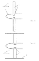
- the Fig. 1 shows a substantially elliptical hub cone 1 with a propeller 2 of a turboprop aircraft engine according to the prior art.
- the Fig. 2 shows a substantially elliptical hub cone 1 with a jacketed by a housing 4 fan (fan) 3 of an aircraft engine according to the state of the technique.
- the incoming flow is indicated by an arrow 5.
- the aircraft engine with the propeller 2 ( Fig. 1 ) or with the fan 4 enveloped by the housing 4 FIG. Fig.
- a regularly elliptical shape exhibiting hub cone 1 is arranged, which should be designed so that the incoming flow is performed as low as possible to the hub radius of the propeller 2 and 3 blower ,
- the hub cone 1 rotates with the propeller 2 or blower 3.
- a boundary layer 6 which grows with the run length is formed along the contour (FIG. Fig. 3 ) out. This boundary layer 6 causes the hub cone 1 of the propeller 2 and the fan 3 is unfavorably, ie very slowly and at a steep angle of attack, is flown
- the losses reduce the efficiency, and the unfavorable outflow negatively influences the efficiency and the flow conditions at the subsequent engine components.
- Fig. 5 shows a hub profile 12 and the direction of rotation 13th
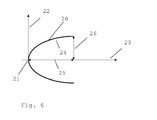
- FIGS Fig. 6 the origin of the xr coordinate system at the tip 21 of the hub cone 20, which is perpendicular to the horizontal cone or machine axis 23 and radial r-axis 22, the outer contour 24 of the hub cone 20 and the maximum dimensions 25 and 26 of the hub cone 20 in x Direction or in the r direction.
- the invention defines a family of optimal shapes of the geometry of the hub cone 20. This can be defined using the mathematical equation such that its course is continuous and monotonic and thus no disruption of the boundary layer occurs.
- a set of cone shapes can be defined which produce a minimum loss and a minimum boundary layer thickness.
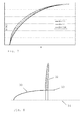
- the set of curves defined in this way comprises according to Fig. 7 all values of M between 1.50 and 1.98.
- the minimum loss is generated by the shapes generated with the values of M between 1.89 and 1.945.
- the hub shapes produced with the given equation and values for the M value, which describes the S (x) form, have a 17% lower loss for a test case than, for example, an elliptical hub contour, usually for the hub contour of a propeller 2 is selected.
- the optimal hub contour leads to better flow of the propeller 2 or 3 blower, which is thus more efficient, and it reduces the drag coefficient of the hub cone 20. Both leads to reduced fuel consumption.
- FIG. 8 An embodiment of an inventively optimized hub cone 30 with hub body 33 and machine or cone axis 34 for a single propeller 32 as a tractor configuration is in Fig. 8 shown. Here the hub cone rotates.
- a further exemplary embodiment of an inventively optimized hub cone 40 with hub body 43 and machine or cone axis 44 for a double propeller 34 as a pusher configuration is disclosed in US Pat Fig. 8 shown. Here the hub cone is fixed.
Landscapes
- Engineering & Computer Science (AREA)
- Chemical & Material Sciences (AREA)
- Combustion & Propulsion (AREA)
- Mechanical Engineering (AREA)
- General Engineering & Computer Science (AREA)
- Aviation & Aerospace Engineering (AREA)
- Structures Of Non-Positive Displacement Pumps (AREA)
Applications Claiming Priority (1)
| Application Number | Priority Date | Filing Date | Title |
|---|---|---|---|
| DE102008055631A DE102008055631A1 (de) | 2008-11-03 | 2008-11-03 | Nabenkonus für ein Flugzeugtriebwerk |
Publications (2)
| Publication Number | Publication Date |
|---|---|
| EP2182176A2 true EP2182176A2 (fr) | 2010-05-05 |
| EP2182176A3 EP2182176A3 (fr) | 2015-11-18 |
Family
ID=41210830
Family Applications (1)
| Application Number | Title | Priority Date | Filing Date |
|---|---|---|---|
| EP09172753.7A Withdrawn EP2182176A3 (fr) | 2008-11-03 | 2009-10-12 | Cône d'entrée pour un moteur d'avion |
Country Status (3)
| Country | Link |
|---|---|
| US (1) | US8251654B2 (fr) |
| EP (1) | EP2182176A3 (fr) |
| DE (1) | DE102008055631A1 (fr) |
Citations (2)
| Publication number | Priority date | Publication date | Assignee | Title |
|---|---|---|---|---|
| US4796424A (en) | 1986-10-16 | 1989-01-10 | Rolls-Royce Plc | Intake for a turbopropeller gas turbine engine |
| US20040179941A1 (en) | 2003-02-10 | 2004-09-16 | Dimitrie Negulescu | Turboprop engine with co-rotating two-stage high-performance propeller |
Family Cites Families (10)
| Publication number | Priority date | Publication date | Assignee | Title |
|---|---|---|---|---|
| US1402539A (en) * | 1917-09-14 | 1922-01-03 | Oscar A Ross | Aeroplane propeller or the like |
| US2934150A (en) * | 1955-12-21 | 1960-04-26 | United Aircraft Corp | Pressure-contoured spinner |
| GB858706A (en) * | 1957-02-18 | 1961-01-11 | United Aircraft Corp | Drag-reducing devices for aircraft propellers |
| US4419053A (en) * | 1981-11-20 | 1983-12-06 | Fairchild Swearingen Corporation | Propeller spinner |
| FR2605587B1 (fr) * | 1986-10-23 | 1989-06-16 | Onera (Off Nat Aerospatiale) | Perfectionnements apportes aux helices aeriennes, notamment pour propulseurs d'aeronef |
| US5224833A (en) * | 1989-02-28 | 1993-07-06 | Rolls-Royce Plc | Fan for a gas turbine engine air intake |
| US5167489A (en) * | 1991-04-15 | 1992-12-01 | General Electric Company | Forward swept rotor blade |
| JP5259919B2 (ja) * | 2005-07-21 | 2013-08-07 | ダイキン工業株式会社 | 軸流ファン |
| GB0526182D0 (en) * | 2005-12-22 | 2006-02-01 | Watts Alan E | Propeller |
| DE102008035160A1 (de) * | 2008-07-28 | 2010-02-04 | Rolls-Royce Deutschland Ltd & Co Kg | Verfahren zur Verbesserung der Strömungsverhältnisse am Propeller oder Fan eines Flugzeugtriebwerks und danach ausgebildeter Nabenkonus |
-
2008
- 2008-11-03 DE DE102008055631A patent/DE102008055631A1/de not_active Withdrawn
-
2009
- 2009-10-12 EP EP09172753.7A patent/EP2182176A3/fr not_active Withdrawn
- 2009-11-02 US US12/610,903 patent/US8251654B2/en not_active Expired - Fee Related
Patent Citations (2)
| Publication number | Priority date | Publication date | Assignee | Title |
|---|---|---|---|---|
| US4796424A (en) | 1986-10-16 | 1989-01-10 | Rolls-Royce Plc | Intake for a turbopropeller gas turbine engine |
| US20040179941A1 (en) | 2003-02-10 | 2004-09-16 | Dimitrie Negulescu | Turboprop engine with co-rotating two-stage high-performance propeller |
Also Published As
| Publication number | Publication date |
|---|---|
| DE102008055631A1 (de) | 2010-05-06 |
| EP2182176A3 (fr) | 2015-11-18 |
| US20100111702A1 (en) | 2010-05-06 |
| US8251654B2 (en) | 2012-08-28 |
Similar Documents
| Publication | Publication Date | Title |
|---|---|---|
| EP2337950B1 (fr) | Profil d'une pale de rotor et pale de rotor d'une éolienne | |
| EP0990090B1 (fr) | Pale de rotor d'un moteur a ecoulement axial | |
| DE3781763T2 (de) | Verlustarmes propellerblatt fuer ueberschallbereich. | |
| EP2959161B1 (fr) | Pale de rotor d'une éolienne | |
| EP1524431B1 (fr) | Pale pour éolienne avec volets de bord de fuite | |
| EP3803711B1 (fr) | Conception et fabrication d'une aube de turbomachine | |
| DE102013225642B4 (de) | Abgasturbolader mit einem verstellbaren Leitgitter | |
| EP0846867A2 (fr) | Turbomachine avec un étage de compression transsonique | |
| EP2334549B1 (fr) | Pale pour turbomachine | |
| EP3172447B1 (fr) | Aube de rotor | |
| EP2294286B1 (fr) | Rotor avex aubes mobiles carenées d'une turbomachine | |
| EP3536974B1 (fr) | Compresseur de turbine à gaz | |
| DE102013207640B4 (de) | Windenergieanlagen-Rotorblatt | |
| EP3665384B1 (fr) | Pale de rotor d'un rotor d'un aérogénérateur, aérogénérateur et procédé d'amélioration du taux de rendement d'un rotor d'un aérogénérateur | |
| EP3260660B1 (fr) | Aube directrice ou mobile comprenant des zones en relief | |
| WO2012164045A1 (fr) | Rotor d'éolienne comportant une pale courbée | |
| EP0937862B1 (fr) | Disposition des aubes des turbines axiales | |
| EP3078804A1 (fr) | Agencement virole pour une rangée d'aubes de rotor ou stator et turbine associée | |
| DE102014206217A1 (de) | Verdichtungsgitter für einen Axialverdichter | |
| DE102012104240B4 (de) | Hybridströmungs-Schaufeldesigns | |
| EP3066337A1 (fr) | Pale de rotor d'une éolienne et éolienne | |
| WO2018046519A1 (fr) | Pale de rotor d'éolienne | |
| DE102016217093A1 (de) | Koppelbolzen sowie Turbine mit Koppelbolzen | |
| EP2182176A2 (fr) | Cône d'entrée pour un moteur d'avion | |
| EP2232058B1 (fr) | Turbine à air pour centrale houlomotrice |
Legal Events
| Date | Code | Title | Description |
|---|---|---|---|
| PUAI | Public reference made under article 153(3) epc to a published international application that has entered the european phase |
Free format text: ORIGINAL CODE: 0009012 |
|
| AK | Designated contracting states |
Kind code of ref document: A2 Designated state(s): AT BE BG CH CY CZ DE DK EE ES FI FR GB GR HR HU IE IS IT LI LT LU LV MC MK MT NL NO PL PT RO SE SI SK SM TR |
|
| PUAL | Search report despatched |
Free format text: ORIGINAL CODE: 0009013 |
|
| RIC1 | Information provided on ipc code assigned before grant |
Ipc: F02C 7/04 20060101ALI20151008BHEP Ipc: B64D 33/02 20060101ALI20151008BHEP Ipc: B64C 11/14 20060101AFI20151008BHEP Ipc: F01D 25/00 20060101ALI20151008BHEP |
|
| AK | Designated contracting states |
Kind code of ref document: A3 Designated state(s): AT BE BG CH CY CZ DE DK EE ES FI FR GB GR HR HU IE IS IT LI LT LU LV MC MK MT NL NO PL PT RO SE SI SK SM TR |
|
| 17P | Request for examination filed |
Effective date: 20160425 |
|
| RBV | Designated contracting states (corrected) |
Designated state(s): AT BE BG CH CY CZ DE DK EE ES FI FR GB GR HR HU IE IS IT LI LT LU LV MC MK MT NL NO PL PT RO SE SI SK SM TR |
|
| STAA | Information on the status of an ep patent application or granted ep patent |
Free format text: STATUS: EXAMINATION IS IN PROGRESS |
|
| 17Q | First examination report despatched |
Effective date: 20170320 |
|
| STAA | Information on the status of an ep patent application or granted ep patent |
Free format text: STATUS: THE APPLICATION IS DEEMED TO BE WITHDRAWN |
|
| 18D | Application deemed to be withdrawn |
Effective date: 20170801 |