EP2182178B1 - Gasturbinentriebwerk mit einem Partikelabscheider sowie Verfahren zur Trennung von Partikeln im Betrieb des Gasturbinentriebwerks - Google Patents
Gasturbinentriebwerk mit einem Partikelabscheider sowie Verfahren zur Trennung von Partikeln im Betrieb des Gasturbinentriebwerks Download PDFInfo
- Publication number
- EP2182178B1 EP2182178B1 EP09250762.3A EP09250762A EP2182178B1 EP 2182178 B1 EP2182178 B1 EP 2182178B1 EP 09250762 A EP09250762 A EP 09250762A EP 2182178 B1 EP2182178 B1 EP 2182178B1
- Authority
- EP
- European Patent Office
- Prior art keywords
- cavity
- compressor
- air
- particles
- gas turbine
- Prior art date
- Legal status (The legal status is an assumption and is not a legal conclusion. Google has not performed a legal analysis and makes no representation as to the accuracy of the status listed.)
- Ceased
Links
- 239000002245 particle Substances 0.000 title claims description 55
- 238000000034 method Methods 0.000 title claims description 7
- 239000003570 air Substances 0.000 description 35
- 239000007789 gas Substances 0.000 description 19
- 238000000926 separation method Methods 0.000 description 6
- 239000000567 combustion gas Substances 0.000 description 2
- 239000000446 fuel Substances 0.000 description 2
- 238000012986 modification Methods 0.000 description 2
- 230000004048 modification Effects 0.000 description 2
- 239000004576 sand Substances 0.000 description 2
- 230000002411 adverse Effects 0.000 description 1
- 239000012080 ambient air Substances 0.000 description 1
- 239000000428 dust Substances 0.000 description 1
- 238000000605 extraction Methods 0.000 description 1
- 239000011369 resultant mixture Substances 0.000 description 1
Images


Classifications
-
- F—MECHANICAL ENGINEERING; LIGHTING; HEATING; WEAPONS; BLASTING
- F02—COMBUSTION ENGINES; HOT-GAS OR COMBUSTION-PRODUCT ENGINE PLANTS
- F02C—GAS-TURBINE PLANTS; AIR INTAKES FOR JET-PROPULSION PLANTS; CONTROLLING FUEL SUPPLY IN AIR-BREATHING JET-PROPULSION PLANTS
- F02C7/00—Features, components parts, details or accessories, not provided for in, or of interest apart form groups F02C1/00 - F02C6/00; Air intakes for jet-propulsion plants
- F02C7/04—Air intakes for gas-turbine plants or jet-propulsion plants
- F02C7/05—Air intakes for gas-turbine plants or jet-propulsion plants having provisions for obviating the penetration of damaging objects or particles
- F02C7/052—Air intakes for gas-turbine plants or jet-propulsion plants having provisions for obviating the penetration of damaging objects or particles with dust-separation devices
-
- F—MECHANICAL ENGINEERING; LIGHTING; HEATING; WEAPONS; BLASTING
- F02—COMBUSTION ENGINES; HOT-GAS OR COMBUSTION-PRODUCT ENGINE PLANTS
- F02C—GAS-TURBINE PLANTS; AIR INTAKES FOR JET-PROPULSION PLANTS; CONTROLLING FUEL SUPPLY IN AIR-BREATHING JET-PROPULSION PLANTS
- F02C6/00—Plural gas-turbine plants; Combinations of gas-turbine plants with other apparatus; Adaptations of gas-turbine plants for special use
- F02C6/04—Gas-turbine plants providing heated or pressurised working fluid for other apparatus, e.g. without mechanical power output
- F02C6/06—Gas-turbine plants providing heated or pressurised working fluid for other apparatus, e.g. without mechanical power output providing compressed gas
- F02C6/08—Gas-turbine plants providing heated or pressurised working fluid for other apparatus, e.g. without mechanical power output providing compressed gas the gas being bled from the gas-turbine compressor
-
- F—MECHANICAL ENGINEERING; LIGHTING; HEATING; WEAPONS; BLASTING
- F04—POSITIVE - DISPLACEMENT MACHINES FOR LIQUIDS; PUMPS FOR LIQUIDS OR ELASTIC FLUIDS
- F04D—NON-POSITIVE-DISPLACEMENT PUMPS
- F04D29/00—Details, component parts, or accessories
- F04D29/40—Casings; Connections of working fluid
- F04D29/42—Casings; Connections of working fluid for radial or helico-centrifugal pumps
- F04D29/4206—Casings; Connections of working fluid for radial or helico-centrifugal pumps especially adapted for elastic fluid pumps
- F04D29/4213—Casings; Connections of working fluid for radial or helico-centrifugal pumps especially adapted for elastic fluid pumps suction ports
-
- F—MECHANICAL ENGINEERING; LIGHTING; HEATING; WEAPONS; BLASTING
- F05—INDEXING SCHEMES RELATING TO ENGINES OR PUMPS IN VARIOUS SUBCLASSES OF CLASSES F01-F04
- F05D—INDEXING SCHEME FOR ASPECTS RELATING TO NON-POSITIVE-DISPLACEMENT MACHINES OR ENGINES, GAS-TURBINES OR JET-PROPULSION PLANTS
- F05D2260/00—Function
- F05D2260/60—Fluid transfer
- F05D2260/607—Preventing clogging or obstruction of flow paths by dirt, dust, or foreign particles
-
- Y—GENERAL TAGGING OF NEW TECHNOLOGICAL DEVELOPMENTS; GENERAL TAGGING OF CROSS-SECTIONAL TECHNOLOGIES SPANNING OVER SEVERAL SECTIONS OF THE IPC; TECHNICAL SUBJECTS COVERED BY FORMER USPC CROSS-REFERENCE ART COLLECTIONS [XRACs] AND DIGESTS
- Y02—TECHNOLOGIES OR APPLICATIONS FOR MITIGATION OR ADAPTATION AGAINST CLIMATE CHANGE
- Y02T—CLIMATE CHANGE MITIGATION TECHNOLOGIES RELATED TO TRANSPORTATION
- Y02T50/00—Aeronautics or air transport
- Y02T50/60—Efficient propulsion technologies, e.g. for aircraft
Definitions
- the technical field relates generally to gas turbine engines, and more particularly to the separation or removal of particles from the bleed air prior to use thereof.
- a secondary stream of air is extracted, or "bled", from the main stream, typically in the cold section, for various uses.
- a secondary stream of cold, low-pressure air is extracted from the gas path of the compressor impeller, through a compressor shroud, and is used to pressurize and provide the air to the bearing cavities.
- particles such as dust, sand or the like may be present in the main stream and the secondary bleed air stream, which is undesirable. Improvement is thus sought.
- a gas turbine engine having the features of the preamble of claim 1 is disclosed in US 2007/0144139 A1 .
- Fig. 1 illustrates a gas turbine engine 10 of a type preferably provided for use in subsonic flight, generally comprising in serial flow communication a fan 12 through which ambient air is propelled, a multistage compressor 14 for pressurizing the air, a combustor 16 in which the compressed air is mixed with fuel and ignited for generating an annular stream of hot combustion gases, and a turbine section 18 for extracting energy from the combustion gases.
- a gas turbine engine 10 of a type preferably provided for use in subsonic flight, generally comprising in serial flow communication a fan 12 through which ambient air is propelled, a multistage compressor 14 for pressurizing the air, a combustor 16 in which the compressed air is mixed with fuel and ignited for generating an annular stream of hot combustion gases, and a turbine section 18 for extracting energy from the combustion gases.
- Fuel is injected into the combustor 16 of the gas turbine engine 10 for mixing with the compressed air from the compressor 14 and ignition of the resultant mixture.
- the fan 12, compressor 14, combustor 16, and turbine 18 are preferably all concentric about a common central longitudinal axis 11 of the gas turbine engine 10.
- the multi-stage compressor 14 includes a low-pressure compressor 20 and a high-pressure compressor 22, whereas the multistage turbine 18 includes a high-pressure turbine 24 and a low-pressure turbine 26.
- the low-pressure compressor 20 is connected to the low-pressure turbine 26 and the high pressure compressor 22 is connected to the high-pressure turbine 24.
- the low-pressure compressor 20 is of the axial compressor type, whereas the high-pressure compressor 22 is of the centrifugal type.
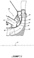
- Fig. 2 illustrates a particle separator 28 for such a gas turbine engine 10. More particularly, Fig. 2 partially shows a compressor 30 of the centrifugal type and which has an impeller 32 with a primary gas path 34. The impeller 32 is surrounded by a compressor case 36 which at least partially defines a cavity 38, generally shaped as a toroid, therein. The cavity 38 surrounds the gas path 34.
- the compressor case 36 has a compressor shroud portion 40 adjacent the impeller 32, and includes a plurality of circumferentially interspaced bleed apertures 42 (only one is shown in Fig. 2 ).
- the bleed apertures 42 allow gas flow communication between the primary gas path 34 and the cavity 38, and thereby allow extracting a secondary bleed flow of air 44, which can be used elsewhere in the engine.
- the bleed apertures 42 are configured (such as in size, shape, orientation and/or location) to allow a substantial tangential velocity component of the air from the primary gas path 34 to flow into the cavity 38.
- the cavity 38 being circumferential to the impeller 32, a swirl movement of air, or circular motion of air (around the main axis 11), can be imparted inside the cavity 38 and maintained by the kinetic energy of the tangential velocity component allowed therein.
- the circular movement of air is used to centrifuge particles which enter the cavity 38 through the bleed apertures 42 radially outwardly, and to convey the particles circumferentially around inside the compressor case 36.
- the particle separator 28 allows bleed air having a significant tangential velocity component to flow into the cavity 38 formed within the compressor case, and is used, in combination with case geometry, to centrifuge the particles radially outwardly and convey the particles circumferentially, away from a clean air outlet, but towards a particle outlet where the particles can be collected and evacuated.
- the cavity 38 funnels radially-outwardly to a narrow circumferential tip 46.
- the narrow circumferential tip 46 acts as a channel 48 for the particles as they are circumferentially conveyed around the cavity 38.
- a clean air outlet 50 of the cavity 38 is provided at a radial position recessed inwardly from the channel 48, such that clean air (i.e. air from which particles have been separated and removed) can be extracted from the particle separator 28 for use elsewhere in the engine.
- the clean air outlet 50 has a re-entrant edge.
- An annular baffle plate 52 extends radially outwardly into the cavity 38 from a location adjacent the bleed apertures 42 on the compressor shroud portion 40 of the compressor case 36, toward the narrow circumferential tip 46 of the cavity 38, and contributes to guide particles ingested through the bleed apertures 42 toward the channel 48.
- the baffle can also prevent particles from passing directly from the bleed apertures 42 to the clean air outlet 50 by forcing airflow around the baffle, to a radially outward portion 48 of the cavity 38.
- the particles are conveyed circumferentially about the channel 48 formed by the narrow circumferential tip 46, they eventually reach a particle outlet 54 provided therein.
- the particle outlet 54 is provided through a lower portion of the compressor case 36, more particularly at the circumferential bottom thereof, and the particle outlet 54 is provided in combination with a particle scoop, or catch, 56 which is tangentially oriented toward the incoming flow of particles, which thereby impinge thereon, and are subsequently guided into the particle outlet 54.
- a tubular channel 58 connects the particle outlet 54 to the atmosphere 60, where the particles can be evacuated.
- a portion of the air is evacuated with the particles through the particle outlet 54. This portion of lost bleed air is however small relative to the amount of air extracted from the clean air outlet 50 ( Fig. 2 ).
- Fig. 4 illustrates an example of slanted bleed apertures 42 in greater detail, wherein each of the bleed apertures 42 defines an aperture axis 41 that is angled in the casing 40 relative to the longitudinal axis 11 of the engine 10 and thereof of the impeller 32.
- the bleed apertures 42 in the casing 40 are tangentially slanted/angled relative to the longitudinal axis 11.
- airflow from the impeller gas path having a significant tangential velocity component is allowed to flow into the annular cavity surrounding the impeller gas path, via a plurality of circumferentially interspaced apertures.
- the tangential velocity of the bleed air allowed into the cavity imparts and maintains a circumferential flow of air in the toroidal shaped cavity, which centrifuges particles ingested therein outward towards a radially inwardly facing channel surrounding the cavity, and about which the particles are conveyed by the air movement to an extraction point, where the separated particles are extracted from the rest of the bleed air flow.
- the particles can thus be substantially separated from the secondary flow of air, such that this secondary air flow is substantially free from particles and can then be extracted from the cavity and re-directed for use elsewhere in the engine.
- the particle separator can be applied to an axial compressor, although an axial compressor may have a lesser tangential velocity component than a centrifugal compressor, and that this may adversely affect separation efficiency.
- more than one clean air outlet, or particle outlet can be used in alternate embodiments. Although the clean air outlet was in the upper portion of the compressor case and the particle outlet was in the bottom of the compressor case in the example above, clean air outlets or particle outlets can alternately be provided at other angular positions.
- the annular baffle is optional but can help increasing separation efficiency, and its exact configuration can be modified as required in alternate embodiments. Variants to the shape, configuration, and relative position of the bleed apertures illustrated herein can be used in alternate embodiments. Further, in alternate embodiments, variants to the generally inverted "V" shape of the radially outwardly funnelling cavity can be used.
- a separation efficiency above 95% will be judged satisfactory.
- a separation efficiency of above 90% or above 70% can also be satisfactory for some applications. Nonetheless, even a separation efficiency lower than 70% can be satisfactory for some applications.
Landscapes
- Engineering & Computer Science (AREA)
- Chemical & Material Sciences (AREA)
- Combustion & Propulsion (AREA)
- Mechanical Engineering (AREA)
- General Engineering & Computer Science (AREA)
- Structures Of Non-Positive Displacement Pumps (AREA)
- Centrifugal Separators (AREA)
Claims (10)
- Gasturbinentriebwerk (10) mit einem Kompressor (14) mit einem Kompressorrotor (22), der um eine Hauptlängsachse (11) des Triebwerks (10) rotierbar ist und in einem Kompressorgehäuse (36) untergebracht ist, wobei das Kompressorgehäuse (36) zumindest teilweise darin einen toroidalen internen Hohlraum (38) definiert, der einen Gaspfad (34) des Kompressors (14) umgibt, das Kompressorgehäuse (36) eine Vielzahl von umlaufenden, voneinander beabstandeten Ablassöffnungen (42) darin aufweist, die Gasflusskommunikation zwischen dem Gaspfad (34) und dem Hohlraum (38) bereitstellen, das Kompressorgehäuse (36) einen Luftauslass (50) in Gasflusskommunikation zum Extrahieren von sauberer Luft davon aufweist, wobei sich der Hohlraum (38) radial nach außen zu einer sich umlaufend erweiternden schmalen Spitze (46) trichterförmig erweitert und dadurch gekennzeichnet, dass: die Ablassöffnungen (42) in einem sich tangential erweiternden Winkel relativ zu der Hauptlängsachse (11) orientiert sind, um einer tangentialen Geschwindigkeitskomponente der Ablassluft, die während des Betriebs des Gasturbinentriebwerks (10) über die Öffnungen (42) in den Hohlraum (38) eintritt, zu ermöglichen, in der Ablassluft vorhandene Partikel radial nach außen in Richtung der sich umlaufend erweiternden schmalen Spitze (46) des Hohlraums (38) zu zentrifugieren und die Partikel umlaufend darum zu einem Partikelauslass (50) zu transportieren, wobei der Luftauslass (54) radial von der schmalen Spitze (46) des Hohlraumes (38) nach innen positioniert ist.
- Gasturbinentriebwerk nach Anspruch 1, weiter umfassend eine ringförmige Ablenkplatte (52), die mit einem Kompressorabdeckteil des Kompressorgehäuses (36) neben den Ablassöffnungen (42) verbunden ist, wobei sich die Ablenkplatte (32) radial nach außen von dem Kompressorabdeckteil zu der schmalen Spitze (46) des Hohlraums (38) erstreckt, zwischen den Ablassöffnungen (42) und dem Luftauslass (50).
- Gasturbinentriebwerk nach Anspruch 1 oder 2, wobei der Luftauslass (50) in einem oberen Teil des Kompressorgehäuses (36) positioniert ist.
- Gasturbinentriebwerk nach einem vorhergehenden Anspruch, wobei der Partikelauslass (54) in einem umlaufenden Bodenteil des Kompressorgehäuses (36) positioniert ist.
- Gasturbinentriebwerk nach einem vorhergehenden Anspruch, weiter umfassend eine Fangplatte (56), die mit dem Kompressorgehäuse (36) in der schmalen radial nach außen gehenden Spitze (46) des Hohlraums (38) verbunden ist, neben dem Partikelauslass (54) und gewinkelt in Bezug auf die tangentiale Geschwindigkeitskomponente der Ablassluft, um die zentrifugierten Partikel in den Partikelauslass (54) zu lenken.
- Gasturbinentriebwerk nach einem vorhergehenden Anspruch, wobei der Kompressor ein Zentrifugalkompressor ist und der Rotor (22) ein Impeller ist.
- Verfahren zur Trennung von Partikeln aus der Luft während des Betriebs eines Gasturbinentriebwerks (10), wobei das Verfahren Folgendes umfasst:Extrahieren von Ablassluft von einem Kompressorgaspfad (34) in einen im Allgemeinen toroidalen Hohlraum (38), der den Gaspfad über eine Vielzahl von umlaufenden voneinander beabstandeten Öffnungen (42), die orientiert sind, um eine tangentiale Geschwindigkeit der Ablassluft in dem Hohlraum (38) zu maximieren, umgibt;Zentrifugieren von Partikeln radial nach außen in einen in dem Hohlraum (38) gebildeten Kanal (48) unter Nutzung der tangentialen Geschwindigkeit der Ablassluft, die in dem Hohlraum (38) fließt, und Aufrechterhalten eines umlaufenden Flusses der Ablassluft in dem Hohlraum, um die Partikel umlaufend um den Kanal zu einem Partikelausgang (54) zu lenken;Extrahieren der Partikel von innerhalb des Kanals (48) des Hohlraumes (38) über den Partikelausgang (54); undExtrahieren sauberer Luft von dem Hohlraum (38) über einen Ausgang für saubere Luft (50), wobei die saubere Luft im Wesentlichen frei von Partikeln ist oder weniger davon aufweist.
- Verfahren nach Anspruch 7, weiter umfassend das Verhindern, dass die Ablassluft direkt von den Einlassöffnungen (42) zu dem Ausgang für saubere Luft (50) des Hohlraumes (38) übergeht, ohne zuerst umlaufend umgeleitet zu werden.
- Verfahren nach Anspruch 7 oder 8, wobei der Schritt des Extrahierens der Partikel das Evakuieren einer Menge der Ablassluft mit den Partikeln enthält.
- Verfahren nach einem der Ansprüche 7 bis 9, wobei der Schritt des Extrahierens der sauberen Luft das Extrahieren der sauberen Luft von einem Ort in dem Hohlraum (38), der von dem Kanal (48) radial nach innen ausgespart ist, enthält.
Applications Claiming Priority (1)
| Application Number | Priority Date | Filing Date | Title |
|---|---|---|---|
| US12/259,602 US8092145B2 (en) | 2008-10-28 | 2008-10-28 | Particle separator and separating method for gas turbine engine |
Publications (3)
| Publication Number | Publication Date |
|---|---|
| EP2182178A2 EP2182178A2 (de) | 2010-05-05 |
| EP2182178A3 EP2182178A3 (de) | 2013-05-01 |
| EP2182178B1 true EP2182178B1 (de) | 2016-03-16 |
Family
ID=40578209
Family Applications (1)
| Application Number | Title | Priority Date | Filing Date |
|---|---|---|---|
| EP09250762.3A Ceased EP2182178B1 (de) | 2008-10-28 | 2009-03-19 | Gasturbinentriebwerk mit einem Partikelabscheider sowie Verfahren zur Trennung von Partikeln im Betrieb des Gasturbinentriebwerks |
Country Status (3)
| Country | Link |
|---|---|
| US (1) | US8092145B2 (de) |
| EP (1) | EP2182178B1 (de) |
| CA (1) | CA2671718C (de) |
Families Citing this family (41)
| Publication number | Priority date | Publication date | Assignee | Title |
|---|---|---|---|---|
| US10286407B2 (en) | 2007-11-29 | 2019-05-14 | General Electric Company | Inertial separator |
| US20100172753A1 (en) * | 2009-01-08 | 2010-07-08 | Frank Lin | Compressor side inlet with improved aerodynamic performance and reduced manufacturing complexity |
| US8561411B2 (en) * | 2009-09-02 | 2013-10-22 | United Technologies Corporation | Air particle separator for a gas turbine engine |
| US8945254B2 (en) | 2011-12-21 | 2015-02-03 | General Electric Company | Gas turbine engine particle separator |
| US8926268B2 (en) * | 2012-03-08 | 2015-01-06 | Hamilton Sundstrand Corporation | Bleed noise reduction |
| US9067163B2 (en) | 2013-04-26 | 2015-06-30 | Hamilton Sundstrand Corporation | Particle separator |
| US9272293B2 (en) | 2013-04-29 | 2016-03-01 | Hamilton Sundstrand Corporation | Particle separator |
| CA2859441C (en) | 2013-08-16 | 2021-10-12 | Eric Loth | Particle separator |
| US9650916B2 (en) | 2014-04-09 | 2017-05-16 | Honeywell International Inc. | Turbomachine cooling systems |
| US11033845B2 (en) | 2014-05-29 | 2021-06-15 | General Electric Company | Turbine engine and particle separators therefore |
| US9915176B2 (en) | 2014-05-29 | 2018-03-13 | General Electric Company | Shroud assembly for turbine engine |
| WO2016025056A2 (en) | 2014-05-29 | 2016-02-18 | General Electric Company | Turbine engine and particle separators therefore |
| WO2016032585A2 (en) | 2014-05-29 | 2016-03-03 | General Electric Company | Turbine engine, components, and methods of cooling same |
| US10036319B2 (en) | 2014-10-31 | 2018-07-31 | General Electric Company | Separator assembly for a gas turbine engine |
| US10167725B2 (en) | 2014-10-31 | 2019-01-01 | General Electric Company | Engine component for a turbine engine |
| US10267179B2 (en) * | 2014-12-31 | 2019-04-23 | General Electric Company | Dirt extraction apparatus for a gas turbine engine |
| US10012147B2 (en) | 2015-08-17 | 2018-07-03 | United Technologies Corporation | Apparatus and method for air particle separator in gas turbine engine |
| US10287992B2 (en) | 2015-08-26 | 2019-05-14 | General Electric Company | Gas turbine engine hybrid variable bleed valve |
| US10835848B2 (en) | 2015-09-21 | 2020-11-17 | Raytheon Technologies Corporation | Apparatus and method for air particle capture in a gas turbine engine |
| US10202903B2 (en) | 2015-09-22 | 2019-02-12 | United Technologies Corporation | Apparatus and method for air particle separation in a gas turbine engine |
| US10428664B2 (en) | 2015-10-15 | 2019-10-01 | General Electric Company | Nozzle for a gas turbine engine |
| US9988936B2 (en) | 2015-10-15 | 2018-06-05 | General Electric Company | Shroud assembly for a gas turbine engine |
| US10174620B2 (en) | 2015-10-15 | 2019-01-08 | General Electric Company | Turbine blade |
| US10196982B2 (en) | 2015-11-04 | 2019-02-05 | General Electric Company | Gas turbine engine having a flow control surface with a cooling conduit |
| US10724436B2 (en) | 2016-01-21 | 2020-07-28 | General Electric Company | Inlet particle separator for a turbine engine |
| US10227930B2 (en) | 2016-03-28 | 2019-03-12 | General Electric Company | Compressor bleed systems in turbomachines and methods of extracting compressor airflow |
| US10208628B2 (en) * | 2016-03-30 | 2019-02-19 | Honeywell International Inc. | Turbine engine designs for improved fine particle separation efficiency |
| US10400670B2 (en) | 2016-06-15 | 2019-09-03 | General Electric Company | Inlet particle separator for a turbine engine |
| US10704425B2 (en) | 2016-07-14 | 2020-07-07 | General Electric Company | Assembly for a gas turbine engine |
| US10695704B2 (en) | 2016-07-20 | 2020-06-30 | General Electric Company | Multi-station debris separation system |
| US10400795B2 (en) * | 2016-07-20 | 2019-09-03 | General Electric Company | High pressure cyclonic separator for turbomachinery |
| US10830138B2 (en) | 2016-07-20 | 2020-11-10 | General Electric Company | Fine debris multi-stage separation system |
| US10393021B2 (en) | 2016-09-01 | 2019-08-27 | Rolls-Royce North American Technologies Inc. | Particle separator |
| US20180135516A1 (en) * | 2016-11-16 | 2018-05-17 | Honeywell International Inc. | Scavenge methodologies for turbine engine particle separation concepts |
| US10738699B2 (en) | 2018-01-19 | 2020-08-11 | Rolls-Royce North American Technologies Inc. | Air-inlet particle separator having a bleed surface |
| US11035257B2 (en) | 2018-01-23 | 2021-06-15 | Honeywell International Inc. | Driven cavity particle separator |
| US10816014B2 (en) | 2018-07-25 | 2020-10-27 | Honeywell International Inc. | Systems and methods for turbine engine particle separation |
| US11371434B2 (en) | 2020-08-19 | 2022-06-28 | Honeywell International Inc. | Compressor particle separator for gas turbine engine |
| US11421709B2 (en) * | 2020-09-08 | 2022-08-23 | Honeywell International Inc. | Systems for interstage particle separation in multistage radial compressors of turbine engines |
| EP4435264A1 (de) * | 2023-03-21 | 2024-09-25 | Rolls-Royce plc | Luftdruckbeaufschlagungssystem |
| US12392284B1 (en) | 2024-02-13 | 2025-08-19 | General Electric Company | Cyclonic separator for gas turbine engine |
Family Cites Families (23)
| Publication number | Priority date | Publication date | Assignee | Title |
|---|---|---|---|---|
| DE1026916B (de) * | 1955-05-06 | 1958-03-27 | Licentia Gmbh | Turbogeblaese fuer staubhaltige Gase |
| US3673771A (en) | 1970-11-23 | 1972-07-04 | Avco Corp | Multi-channel particle separator |
| BE791726A (fr) * | 1971-11-23 | 1973-05-22 | Gen Electric | Separateur de particules avec dispositif de balayage en colimacon |
| US3751907A (en) | 1971-12-08 | 1973-08-14 | Caterpillar Tractor Co | Inertial air cleaner for gas turbine |
| US3993463A (en) | 1975-08-28 | 1976-11-23 | The United States Of America As Represented By The Secretary Of The Army | Particle separator for turbine engines of aircraft |
| US4304094A (en) | 1979-11-16 | 1981-12-08 | United Technologies Corp. | Engine air particle separator for use with gas turbine engine |
| US4798047A (en) | 1983-12-19 | 1989-01-17 | Elliott Turbomachinery Co., Inc. | Particulate collection and cooling in a turbomachine |
| US4702071A (en) * | 1985-06-28 | 1987-10-27 | Rolls-Royce Plc | Inlet particle separator |
| GB2203801B (en) | 1987-04-14 | 1991-11-27 | Rolls Royce Plc | A gas turbine engine |
| US4928480A (en) * | 1988-03-04 | 1990-05-29 | General Electric Company | Separator having multiple particle extraction passageways |
| US5431535C1 (en) | 1989-12-05 | 2001-01-09 | Boeing Co | Foreign matter diverter systems for turbofan engines |
| US5253472A (en) | 1990-02-28 | 1993-10-19 | Dev Sudarshan P | Small gas turbine having enhanced fuel economy |
| DE4326799A1 (de) | 1993-08-10 | 1995-02-16 | Abb Management Ag | Vorrichtung zur Sekundärluftentnahme aus einem Axialverdichter |
| US5586859A (en) | 1995-05-31 | 1996-12-24 | United Technologies Corporation | Flow aligned plenum endwall treatment for compressor blades |
| US5558496A (en) | 1995-08-21 | 1996-09-24 | General Electric Company | Removing particles from gas turbine coolant |
| EP1147291B1 (de) | 1998-02-26 | 2007-08-22 | Allison Advanced Development Company | Zapfsystem für eine kompressorwand sowie betriebsverfahren |
| JP4358965B2 (ja) | 2000-03-27 | 2009-11-04 | 株式会社日立産機システム | 遠心型羽根車および空気清浄装置 |
| JP3711028B2 (ja) * | 2001-02-20 | 2005-10-26 | 川崎重工業株式会社 | 異物除去構造を備えたガスタービンエンジン |
| ITMI20021218A1 (it) | 2002-06-05 | 2003-12-05 | Nuovo Pignone Spa | Dispositivo di estrazione gas di processo per un compressore assiale avente una buona adattabilita' ad un cambiamento di specifiche operativ |
| DE10330471A1 (de) * | 2003-07-05 | 2005-02-03 | Alstom Technology Ltd | Vorrichtung zum Abscheiden von Fremdpartikeln aus der den Laufschaufeln einer Turbine zuführbaren Kühlluft |
| JP4279245B2 (ja) * | 2004-12-06 | 2009-06-17 | 本田技研工業株式会社 | ガスタービンエンジン |
| US7284953B2 (en) | 2005-08-29 | 2007-10-23 | United Technologies Corporation | Dirt separator for gas turbine air supply |
| US20080152500A1 (en) * | 2006-12-20 | 2008-06-26 | Carsten Mehring | Inertial particle separator for compressor shroud bleed |
-
2008
- 2008-10-28 US US12/259,602 patent/US8092145B2/en active Active
-
2009
- 2009-03-19 EP EP09250762.3A patent/EP2182178B1/de not_active Ceased
- 2009-07-14 CA CA2671718A patent/CA2671718C/en not_active Expired - Fee Related
Also Published As
| Publication number | Publication date |
|---|---|
| EP2182178A3 (de) | 2013-05-01 |
| EP2182178A2 (de) | 2010-05-05 |
| US8092145B2 (en) | 2012-01-10 |
| CA2671718A1 (en) | 2010-04-28 |
| CA2671718C (en) | 2011-07-26 |
| US20100104422A1 (en) | 2010-04-29 |
Similar Documents
| Publication | Publication Date | Title |
|---|---|---|
| EP2182178B1 (de) | Gasturbinentriebwerk mit einem Partikelabscheider sowie Verfahren zur Trennung von Partikeln im Betrieb des Gasturbinentriebwerks | |
| US10450951B2 (en) | Cyclonic separator for a turbine engine | |
| US11541340B2 (en) | Inducer assembly for a turbine engine | |
| US10975731B2 (en) | Turbine engine, components, and methods of cooling same | |
| EP3196442B1 (de) | Einlasspartikelabscheider für einen turbinenmotor | |
| US10167725B2 (en) | Engine component for a turbine engine | |
| US9915176B2 (en) | Shroud assembly for turbine engine | |
| EP3225818B1 (de) | Turbinenmotorentwürfe für verbesserte feinpartikeltrennungseffizienz | |
| US20190046999A9 (en) | Inertial separator | |
| US20140290254A1 (en) | Cyclonic Dirt Separating Turbine Accelerator | |
| US10400670B2 (en) | Inlet particle separator for a turbine engine | |
| US12357933B2 (en) | Inducer assembly for a turbine engine | |
| US20180016944A1 (en) | Assembly for a gas turbine engine | |
| EP3599344A1 (de) | Systeme zur partikelabscheidung von turbinenmotoren |
Legal Events
| Date | Code | Title | Description |
|---|---|---|---|
| PUAI | Public reference made under article 153(3) epc to a published international application that has entered the european phase |
Free format text: ORIGINAL CODE: 0009012 |
|
| AK | Designated contracting states |
Kind code of ref document: A2 Designated state(s): AT BE BG CH CY CZ DE DK EE ES FI FR GB GR HR HU IE IS IT LI LT LU LV MC MK MT NL NO PL PT RO SE SI SK TR |
|
| AX | Request for extension of the european patent |
Extension state: AL BA RS |
|
| PUAL | Search report despatched |
Free format text: ORIGINAL CODE: 0009013 |
|
| AK | Designated contracting states |
Kind code of ref document: A3 Designated state(s): AT BE BG CH CY CZ DE DK EE ES FI FR GB GR HR HU IE IS IT LI LT LU LV MC MK MT NL NO PL PT RO SE SI SK TR |
|
| AX | Request for extension of the european patent |
Extension state: AL BA RS |
|
| RIC1 | Information provided on ipc code assigned before grant |
Ipc: F01D 25/32 20060101AFI20130322BHEP Ipc: F02C 6/08 20060101ALI20130322BHEP Ipc: F02C 7/052 20060101ALI20130322BHEP |
|
| 17P | Request for examination filed |
Effective date: 20131101 |
|
| RBV | Designated contracting states (corrected) |
Designated state(s): AT BE BG CH CY CZ DE DK EE ES FI FR GB GR HR HU IE IS IT LI LT LU LV MC MK MT NL NO PL PT RO SE SI SK TR |
|
| AKX | Designation fees paid |
Designated state(s): DE FR GB |
|
| GRAP | Despatch of communication of intention to grant a patent |
Free format text: ORIGINAL CODE: EPIDOSNIGR1 |
|
| INTG | Intention to grant announced |
Effective date: 20150902 |
|
| GRAS | Grant fee paid |
Free format text: ORIGINAL CODE: EPIDOSNIGR3 |
|
| GRAA | (expected) grant |
Free format text: ORIGINAL CODE: 0009210 |
|
| AK | Designated contracting states |
Kind code of ref document: B1 Designated state(s): DE FR GB |
|
| REG | Reference to a national code |
Ref country code: GB Ref legal event code: FG4D |
|
| REG | Reference to a national code |
Ref country code: DE Ref legal event code: R096 Ref document number: 602009036791 Country of ref document: DE |
|
| REG | Reference to a national code |
Ref country code: FR Ref legal event code: PLFP Year of fee payment: 8 |
|
| REG | Reference to a national code |
Ref country code: DE Ref legal event code: R097 Ref document number: 602009036791 Country of ref document: DE |
|
| PLBE | No opposition filed within time limit |
Free format text: ORIGINAL CODE: 0009261 |
|
| STAA | Information on the status of an ep patent application or granted ep patent |
Free format text: STATUS: NO OPPOSITION FILED WITHIN TIME LIMIT |
|
| REG | Reference to a national code |
Ref country code: FR Ref legal event code: PLFP Year of fee payment: 9 |
|
| 26N | No opposition filed |
Effective date: 20161219 |
|
| REG | Reference to a national code |
Ref country code: DE Ref legal event code: R082 Ref document number: 602009036791 Country of ref document: DE Representative=s name: SCHMITT-NILSON SCHRAUD WAIBEL WOHLFROM PATENTA, DE |
|
| REG | Reference to a national code |
Ref country code: FR Ref legal event code: PLFP Year of fee payment: 10 |
|
| PGFP | Annual fee paid to national office [announced via postgrant information from national office to epo] |
Ref country code: DE Payment date: 20190219 Year of fee payment: 11 Ref country code: GB Payment date: 20190222 Year of fee payment: 11 |
|
| PGFP | Annual fee paid to national office [announced via postgrant information from national office to epo] |
Ref country code: FR Payment date: 20190220 Year of fee payment: 11 |
|
| REG | Reference to a national code |
Ref country code: DE Ref legal event code: R119 Ref document number: 602009036791 Country of ref document: DE |
|
| PG25 | Lapsed in a contracting state [announced via postgrant information from national office to epo] |
Ref country code: DE Free format text: LAPSE BECAUSE OF NON-PAYMENT OF DUE FEES Effective date: 20201001 Ref country code: FR Free format text: LAPSE BECAUSE OF NON-PAYMENT OF DUE FEES Effective date: 20200331 |
|
| GBPC | Gb: european patent ceased through non-payment of renewal fee |
Effective date: 20200319 |
|
| PG25 | Lapsed in a contracting state [announced via postgrant information from national office to epo] |
Ref country code: GB Free format text: LAPSE BECAUSE OF NON-PAYMENT OF DUE FEES Effective date: 20200319 |