EP2182181A1 - Culbuteur - Google Patents
Culbuteur Download PDFInfo
- Publication number
- EP2182181A1 EP2182181A1 EP08017808A EP08017808A EP2182181A1 EP 2182181 A1 EP2182181 A1 EP 2182181A1 EP 08017808 A EP08017808 A EP 08017808A EP 08017808 A EP08017808 A EP 08017808A EP 2182181 A1 EP2182181 A1 EP 2182181A1
- Authority
- EP
- European Patent Office
- Prior art keywords
- roller
- width
- opening
- rocker arm
- ledge
- Prior art date
- Legal status (The legal status is an assumption and is not a legal conclusion. Google has not performed a legal analysis and makes no representation as to the accuracy of the status listed.)
- Withdrawn
Links
- 230000002093 peripheral effect Effects 0.000 claims abstract description 3
- 230000007704 transition Effects 0.000 claims description 4
- 125000006850 spacer group Chemical group 0.000 claims 2
- 230000006835 compression Effects 0.000 description 1
- 238000007906 compression Methods 0.000 description 1
- 239000000463 material Substances 0.000 description 1
- 239000002184 metal Substances 0.000 description 1
- NJPPVKZQTLUDBO-UHFFFAOYSA-N novaluron Chemical compound C1=C(Cl)C(OC(F)(F)C(OC(F)(F)F)F)=CC=C1NC(=O)NC(=O)C1=C(F)C=CC=C1F NJPPVKZQTLUDBO-UHFFFAOYSA-N 0.000 description 1
- 238000005457 optimization Methods 0.000 description 1
- 230000003068 static effect Effects 0.000 description 1
Images

Classifications
-
- F—MECHANICAL ENGINEERING; LIGHTING; HEATING; WEAPONS; BLASTING
- F01—MACHINES OR ENGINES IN GENERAL; ENGINE PLANTS IN GENERAL; STEAM ENGINES
- F01L—CYCLICALLY OPERATING VALVES FOR MACHINES OR ENGINES
- F01L1/00—Valve-gear or valve arrangements, e.g. lift-valve gear
- F01L1/12—Transmitting gear between valve drive and valve
- F01L1/18—Rocking arms or levers
- F01L1/185—Overhead end-pivot rocking arms
Definitions
- the invention relates to a cam follower rocker arm having a U-shaped body which, when inverted, has an intermediate opening at the top, a roller positioned inside the body and accessible through the opening, and is mounted on an axle that is secured to the side of the U-shaped body.
- U.S. Patent No. 4,825,717 includes a U-shaped cross section body with an intermediate opening, the width of which is, the same width as the body inside walls.
- a cam follower roller is positioned between the body side walls and opening. The roller when positioned in the body is captured between the side walls and extends into the intermediate opening and rotates within.
- the body of U.S. Patent No. 4,799,464 describes the use of rectangular opening for a boat style rocker arm of a U-shaped cross section.
- This type of rocker arm differs from the cam follower type in that in the boat style rocker arm is supported in the center by a pedestal having a shank that extends through the window.
- the perpendicular ledge in the side walls of the boat style arm is used to carry loads when operating.
- the invention is distinguishable from the prior art having a body that has a ledge opening with a width at the outside that is less then the inside width at the body opening creating a ledge perpendicular to the body side walls.
- a cylindrical roller has a transition step on both ends of its periphery to allow the smaller width of the roller, when extended, to extend into the outside window and the larger width to maintain a close running clearance to the inside walls of the body when assembled.
- the ledged opening or window in the portion joining the two vertical sides of the U-shaped body may be formed at top or at the bottom of the U-shaped body. This ledge functions to provide a structure that improves the rocker arm stiffness as verifiable by using analytical tools and actual static testing.
- FIG. 1 is a typical end pivot over head cam valve train with a cam follower rocker arm, valve stem and hydraulic lash adjuster.
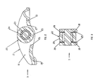
- FIG. 2 is a cross section of prior art that shows the components for a cam follower rocker arm.
- FIG 3 is a cross section of FIG 2 taken about the roller center.
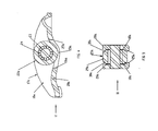
- FIG. 4 is a cross section of the invention that shows the components for a cam follower rocker arm.
- FIG. 5 is a cross section of FIG 4 taken about the roller center.
- the rocker arm in accordance with the invention is of the cam-follower type and is made preferably by cold-forming operation and comprises, a one-piece metal body generally convex body having a U-shaped cross section throughout most of its length with two structurally-integral side walls joined by a perpendicularly positioned wall.
- the rocker arm body includes a recess formed at one end to receive the upper part of a lifter post upon which the rocker arm can pivot and a second recess at the opposite end of the body adapted to receive the end of a valve stem.
- a central part of the wall joining the sides of the U-shape body has a generally rectangular opening. The width or transverse dimension of the rectangular opening is less than the width of the top wall so that the opening extends substantially, but not entirely, from one side of the rocker arm body to the other.
- a cam-contacting roller with a stepped periphery is mounted in the body and is rotatably carried by the rocker arm that permits the peripheral circumferential surface of the stepped roller to be exposed through the rectangular body opening to engage a cam.
- the cam-contacting roller is rotatably mounted on an axle carried by the side walls of the body below the rectangular opening.
- the roller preferably has a multiplicity of needle bearings to provide minimal friction.
- a valve train 10 is comprised of a cam follower rocker arm 11, a hydraulic lash adjuster 12 which engages the cam follower rocker arm 11 at one end, a valve stem 13 which contacts the opposite end of the cam follower rocker arm 11 and a cam 14 located between the hydraulic lash adjuster 12 and valve stem 13 is also in contact with the cam follower rocker arm 11.
- the valve stem 13 extends upwardly from a cylinder head (not shown) through a coiled compression spring 15 which is conventionally seated against the cylinder head and a retaining ring 16 mounted on the valve stem 13.
- the cam 14 is able to rotate. The rotating motion of the cam 14 is transmitted through the cam follower rocker arm 11 which pivots about the hydraulic lash adjuster 12 and moves the valve stem 13 in a linear motion.
- the cam follower rocker arm 11 is comprised of a U-shape body 17 with a vertical surface 18 joined together by a first lower section 20 which contacts the valve stem 13 ( FIG 1 ) and a second lower section 21 which engages the hydraulic lash adjuster 12 ( FIG 1 ). Both lower sections 20, 21 extend perpendicular to the vertical surface 18.
- a cylindrical roller 22 preferably provided within cylindrical needles 23 is mounted on a cylindrical axle 24. The roller 22 contacts the cam 14 ( FIG 1 ) and is located between the vertical surface 18 and extends into an intermediate rectangular window surface 25. Surfaces 26, 27 extend through the lower sections 20, 21 respectively and are wide enough to allow clearance to the roller 22.
- the window surface 25 is the same width as the vertical surface 18.
- the roller end surface 28 and the vertical surface 18 essentially have a total clearance throughout of about 0.2 - 0.8 when assembled.
- the roller outer periphery 29 and roller end (corner) surface 28 extend into the rectangular window surfaces 25, 26 ( FIG 2 ) and 27 ( FIG 2 ) with clearance.
- the invention for a cam follower rocker arm 11 is comprised of a U-shape body 17a with vertical side surfaces 18a joined together by a lower section 20a which has an end that contacts the valve stem 13 ( FIG 1 ) and an opposite end which engages the hydraulic lash adjuster 12 ( FIG 1 ).
- the lower section 20a is perpendicular to the vertical surface 18a.
- a cylindrical roller 22a and cylindrical needles 23 are mounted on a cylindrical axle 24.
- the roller 22a contacts the cam 14 in FIG 1 and is located between the vertical surface 18a and an intermediate rectangular window surface 25a.
- Surfaces 26a, 27a extend through the lower section 20a and are wide enough to allow clearance to the roller 22a.
- the window surface 25a is smaller then the vertical surface 18a creating a ledge that has a minimum distance of 30% material thickness.
- the roller 22a has a transition surface 30a on both ends that allows a total clearance of 0.2 - 0.8 between the vertical surface 18a and the roller end surface 28a.
- the roller outer surface 29a and roller transition surface 30a extend into the rectangular window surfaces 25a, 26a ( FIG 4 ) and 27a ( FIG 4 ) with clearance.
Landscapes
- Engineering & Computer Science (AREA)
- Mechanical Engineering (AREA)
- General Engineering & Computer Science (AREA)
- Valve-Gear Or Valve Arrangements (AREA)
Priority Applications (1)
| Application Number | Priority Date | Filing Date | Title |
|---|---|---|---|
| EP08017808A EP2182181A1 (fr) | 2008-10-10 | 2008-10-10 | Culbuteur |
Applications Claiming Priority (1)
| Application Number | Priority Date | Filing Date | Title |
|---|---|---|---|
| EP08017808A EP2182181A1 (fr) | 2008-10-10 | 2008-10-10 | Culbuteur |
Publications (1)
| Publication Number | Publication Date |
|---|---|
| EP2182181A1 true EP2182181A1 (fr) | 2010-05-05 |
Family
ID=41719065
Family Applications (1)
| Application Number | Title | Priority Date | Filing Date |
|---|---|---|---|
| EP08017808A Withdrawn EP2182181A1 (fr) | 2008-10-10 | 2008-10-10 | Culbuteur |
Country Status (1)
| Country | Link |
|---|---|
| EP (1) | EP2182181A1 (fr) |
Citations (7)
| Publication number | Priority date | Publication date | Assignee | Title |
|---|---|---|---|---|
| GB512021A (en) * | 1938-02-23 | 1939-08-28 | Clifford Towler | Improvements in means for locking or securing pivot pins for the valve gear of internal combustion engines |
| US4727832A (en) * | 1986-06-13 | 1988-03-01 | Mitsubishi Jidosha Kogyo Kabushiki Kaisha | Roller rocker arm |
| JPS643006U (fr) * | 1987-06-23 | 1989-01-10 | ||
| US4799464A (en) | 1983-03-03 | 1989-01-24 | Toledo Stamping & Manufacturing Company | Boat-type rocker arm assembly |
| US4825717A (en) | 1988-09-12 | 1989-05-02 | Henley Manufacturing Corporation | Rocker arm of the cam-follower type with ribs |
| DE10121798A1 (de) * | 2001-05-04 | 2002-11-07 | Audi Ag | Ventiltrieb für eine Brennkraftmaschine |
| US20090078224A1 (en) * | 2007-09-26 | 2009-03-26 | Scott Paul Smith | Cam follower rocker arm |
-
2008
- 2008-10-10 EP EP08017808A patent/EP2182181A1/fr not_active Withdrawn
Patent Citations (7)
| Publication number | Priority date | Publication date | Assignee | Title |
|---|---|---|---|---|
| GB512021A (en) * | 1938-02-23 | 1939-08-28 | Clifford Towler | Improvements in means for locking or securing pivot pins for the valve gear of internal combustion engines |
| US4799464A (en) | 1983-03-03 | 1989-01-24 | Toledo Stamping & Manufacturing Company | Boat-type rocker arm assembly |
| US4727832A (en) * | 1986-06-13 | 1988-03-01 | Mitsubishi Jidosha Kogyo Kabushiki Kaisha | Roller rocker arm |
| JPS643006U (fr) * | 1987-06-23 | 1989-01-10 | ||
| US4825717A (en) | 1988-09-12 | 1989-05-02 | Henley Manufacturing Corporation | Rocker arm of the cam-follower type with ribs |
| DE10121798A1 (de) * | 2001-05-04 | 2002-11-07 | Audi Ag | Ventiltrieb für eine Brennkraftmaschine |
| US20090078224A1 (en) * | 2007-09-26 | 2009-03-26 | Scott Paul Smith | Cam follower rocker arm |
Similar Documents
| Publication | Publication Date | Title |
|---|---|---|
| US4697473A (en) | Rocker arm with cam-contacting roller | |
| JP2719400B2 (ja) | ロッカアーム | |
| JP5137627B2 (ja) | ロッカアームユニット及びロッカアームユニットの組立方法 | |
| KR101931426B1 (ko) | 종동 기구 | |
| US8800519B2 (en) | Roller tappet | |
| CA2037870C (fr) | Culbuteur avec canal arrondi, solidaire d'une tige de soupape avec extremite de forme hemispherique | |
| CN101365865B (zh) | 带有停阀摇臂的气门控制系统 | |
| US8561585B2 (en) | Rocker arm unit | |
| US2905160A (en) | Rocker arm | |
| US20090078224A1 (en) | Cam follower rocker arm | |
| KR20100041111A (ko) | 캠 팔로워 로커암 | |
| EP2182181A1 (fr) | Culbuteur | |
| US4724803A (en) | Rolling contact rocker arm with reaction member, rocker key and roller follower | |
| US6619251B2 (en) | Tappet for an internal combustion engine | |
| US20070221154A1 (en) | Anti-tipping roller follower | |
| US20090126527A1 (en) | Bearing design for a roller finger follower | |
| US10309263B2 (en) | Rocker arm and method of manufacturing the rocker arm | |
| US8281759B2 (en) | Anti-rotation locking mechanism for controlling mechanical play | |
| JP2007032475A (ja) | ロッカアーム | |
| JP2012122372A (ja) | ロッカアームユニット | |
| US7089899B1 (en) | Stamped two-step rocker arm component | |
| EP3455469B1 (fr) | Culbuteur | |
| JP6114684B2 (ja) | ロッカアームの支持機構 | |
| JPH05288015A (ja) | ローラタペット | |
| JP2010090887A (ja) | カムフォロアータイプのロッカーアーム |
Legal Events
| Date | Code | Title | Description |
|---|---|---|---|
| PUAI | Public reference made under article 153(3) epc to a published international application that has entered the european phase |
Free format text: ORIGINAL CODE: 0009012 |
|
| AK | Designated contracting states |
Kind code of ref document: A1 Designated state(s): AT BE BG CH CY CZ DE DK EE ES FI FR GB GR HR HU IE IS IT LI LT LU LV MC MT NL NO PL PT RO SE SI SK TR |
|
| AX | Request for extension of the european patent |
Extension state: AL BA MK RS |
|
| AKY | No designation fees paid | ||
| STAA | Information on the status of an ep patent application or granted ep patent |
Free format text: STATUS: THE APPLICATION IS DEEMED TO BE WITHDRAWN |
|
| 18D | Application deemed to be withdrawn |
Effective date: 20101106 |
|
| REG | Reference to a national code |
Ref country code: DE Ref legal event code: R108 Effective date: 20110405 Ref country code: DE Ref legal event code: 8566 |