EP2182194A2 - Système et procédé pour la réduction de corrosion dans une turbine à gaz - Google Patents
Système et procédé pour la réduction de corrosion dans une turbine à gaz Download PDFInfo
- Publication number
- EP2182194A2 EP2182194A2 EP09174285A EP09174285A EP2182194A2 EP 2182194 A2 EP2182194 A2 EP 2182194A2 EP 09174285 A EP09174285 A EP 09174285A EP 09174285 A EP09174285 A EP 09174285A EP 2182194 A2 EP2182194 A2 EP 2182194A2
- Authority
- EP
- European Patent Office
- Prior art keywords
- combustor
- gas turbine
- gas
- exhaust gas
- fuel
- Prior art date
- Legal status (The legal status is an assumption and is not a legal conclusion. Google has not performed a legal analysis and makes no representation as to the accuracy of the status listed.)
- Withdrawn
Links
- 238000000034 method Methods 0.000 title claims description 14
- 238000005260 corrosion Methods 0.000 title claims description 10
- 230000007797 corrosion Effects 0.000 title claims description 10
- 239000007789 gas Substances 0.000 claims abstract description 208
- 239000000446 fuel Substances 0.000 claims abstract description 67
- NINIDFKCEFEMDL-UHFFFAOYSA-N Sulfur Chemical compound [S] NINIDFKCEFEMDL-UHFFFAOYSA-N 0.000 claims abstract description 52
- 229910052717 sulfur Inorganic materials 0.000 claims abstract description 52
- 239000011593 sulfur Substances 0.000 claims abstract description 52
- 239000000567 combustion gas Substances 0.000 claims abstract description 26
- 238000011144 upstream manufacturing Methods 0.000 claims abstract description 24
- 239000000203 mixture Substances 0.000 claims abstract description 13
- CURLTUGMZLYLDI-UHFFFAOYSA-N Carbon dioxide Chemical compound O=C=O CURLTUGMZLYLDI-UHFFFAOYSA-N 0.000 claims description 61
- 239000001569 carbon dioxide Substances 0.000 claims description 30
- 229910002092 carbon dioxide Inorganic materials 0.000 claims description 30
- 238000010248 power generation Methods 0.000 claims description 23
- RAHZWNYVWXNFOC-UHFFFAOYSA-N Sulphur dioxide Chemical compound O=S=O RAHZWNYVWXNFOC-UHFFFAOYSA-N 0.000 claims description 18
- 239000002826 coolant Substances 0.000 claims description 14
- VNWKTOKETHGBQD-UHFFFAOYSA-N methane Chemical compound C VNWKTOKETHGBQD-UHFFFAOYSA-N 0.000 claims description 12
- 238000011084 recovery Methods 0.000 claims description 10
- 238000000926 separation method Methods 0.000 claims description 8
- 238000010521 absorption reaction Methods 0.000 claims description 7
- 239000012528 membrane Substances 0.000 claims description 7
- 238000001179 sorption measurement Methods 0.000 claims description 7
- 239000003345 natural gas Substances 0.000 claims description 6
- RWSOTUBLDIXVET-UHFFFAOYSA-N Dihydrogen sulfide Chemical compound S RWSOTUBLDIXVET-UHFFFAOYSA-N 0.000 claims description 5
- LSDPWZHWYPCBBB-UHFFFAOYSA-N Methanethiol Chemical compound SC LSDPWZHWYPCBBB-UHFFFAOYSA-N 0.000 claims description 5
- 229910000037 hydrogen sulfide Inorganic materials 0.000 claims description 5
- 239000007791 liquid phase Substances 0.000 claims description 5
- 230000003647 oxidation Effects 0.000 claims description 5
- 238000007254 oxidation reaction Methods 0.000 claims description 5
- 239000002904 solvent Substances 0.000 claims description 5
- 239000002594 sorbent Substances 0.000 claims description 5
- 239000003570 air Substances 0.000 description 21
- MWUXSHHQAYIFBG-UHFFFAOYSA-N Nitric oxide Chemical compound O=[N] MWUXSHHQAYIFBG-UHFFFAOYSA-N 0.000 description 14
- XLYOFNOQVPJJNP-UHFFFAOYSA-N water Substances O XLYOFNOQVPJJNP-UHFFFAOYSA-N 0.000 description 9
- 238000002485 combustion reaction Methods 0.000 description 4
- UGFAIRIUMAVXCW-UHFFFAOYSA-N Carbon monoxide Chemical compound [O+]#[C-] UGFAIRIUMAVXCW-UHFFFAOYSA-N 0.000 description 3
- 238000001816 cooling Methods 0.000 description 3
- 239000003546 flue gas Substances 0.000 description 3
- 239000002184 metal Substances 0.000 description 3
- 229910052751 metal Inorganic materials 0.000 description 3
- MGWGWNFMUOTEHG-UHFFFAOYSA-N 4-(3,5-dimethylphenyl)-1,3-thiazol-2-amine Chemical compound CC1=CC(C)=CC(C=2N=C(N)SC=2)=C1 MGWGWNFMUOTEHG-UHFFFAOYSA-N 0.000 description 2
- 239000012080 ambient air Substances 0.000 description 2
- 239000006227 byproduct Substances 0.000 description 2
- 230000006835 compression Effects 0.000 description 2
- 238000007906 compression Methods 0.000 description 2
- 238000012986 modification Methods 0.000 description 2
- 230000004048 modification Effects 0.000 description 2
- JCXJVPUVTGWSNB-UHFFFAOYSA-N nitrogen dioxide Inorganic materials O=[N]=O JCXJVPUVTGWSNB-UHFFFAOYSA-N 0.000 description 2
- 239000000126 substance Substances 0.000 description 2
- 229910052815 sulfur oxide Inorganic materials 0.000 description 2
- 239000005864 Sulphur Substances 0.000 description 1
- 230000009286 beneficial effect Effects 0.000 description 1
- 238000009835 boiling Methods 0.000 description 1
- 239000003245 coal Substances 0.000 description 1
- 238000007796 conventional method Methods 0.000 description 1
- 239000003344 environmental pollutant Substances 0.000 description 1
- 238000005194 fractionation Methods 0.000 description 1
- 239000005431 greenhouse gas Substances 0.000 description 1
- 239000007788 liquid Substances 0.000 description 1
- 150000002739 metals Chemical class 0.000 description 1
- 239000013618 particulate matter Substances 0.000 description 1
- 239000003208 petroleum Substances 0.000 description 1
- 231100000719 pollutant Toxicity 0.000 description 1
- 125000005575 polycyclic aromatic hydrocarbon group Chemical group 0.000 description 1
- 238000004064 recycling Methods 0.000 description 1
- 239000007787 solid Substances 0.000 description 1
- 150000003463 sulfur Chemical class 0.000 description 1
- -1 sulfur dioxide (SO2) Chemical class 0.000 description 1
- XTQHKBHJIVJGKJ-UHFFFAOYSA-N sulfur monoxide Chemical class S=O XTQHKBHJIVJGKJ-UHFFFAOYSA-N 0.000 description 1
- 231100000331 toxic Toxicity 0.000 description 1
- 230000002588 toxic effect Effects 0.000 description 1
- 239000002699 waste material Substances 0.000 description 1
Images

Classifications
-
- F—MECHANICAL ENGINEERING; LIGHTING; HEATING; WEAPONS; BLASTING
- F02—COMBUSTION ENGINES; HOT-GAS OR COMBUSTION-PRODUCT ENGINE PLANTS
- F02C—GAS-TURBINE PLANTS; AIR INTAKES FOR JET-PROPULSION PLANTS; CONTROLLING FUEL SUPPLY IN AIR-BREATHING JET-PROPULSION PLANTS
- F02C3/00—Gas-turbine plants characterised by the use of combustion products as the working fluid
- F02C3/34—Gas-turbine plants characterised by the use of combustion products as the working fluid with recycling of part of the working fluid, i.e. semi-closed cycles with combustion products in the closed part of the cycle
-
- F—MECHANICAL ENGINEERING; LIGHTING; HEATING; WEAPONS; BLASTING
- F02—COMBUSTION ENGINES; HOT-GAS OR COMBUSTION-PRODUCT ENGINE PLANTS
- F02C—GAS-TURBINE PLANTS; AIR INTAKES FOR JET-PROPULSION PLANTS; CONTROLLING FUEL SUPPLY IN AIR-BREATHING JET-PROPULSION PLANTS
- F02C6/00—Plural gas-turbine plants; Combinations of gas-turbine plants with other apparatus; Adaptations of gas-turbine plants for special use
- F02C6/18—Plural gas-turbine plants; Combinations of gas-turbine plants with other apparatus; Adaptations of gas-turbine plants for special use using the waste heat of gas-turbine plants outside the plants themselves, e.g. gas-turbine power heat plants
-
- F—MECHANICAL ENGINEERING; LIGHTING; HEATING; WEAPONS; BLASTING
- F05—INDEXING SCHEMES RELATING TO ENGINES OR PUMPS IN VARIOUS SUBCLASSES OF CLASSES F01-F04
- F05D—INDEXING SCHEME FOR ASPECTS RELATING TO NON-POSITIVE-DISPLACEMENT MACHINES OR ENGINES, GAS-TURBINES OR JET-PROPULSION PLANTS
- F05D2220/00—Application
- F05D2220/70—Application in combination with
- F05D2220/72—Application in combination with a steam turbine
-
- F—MECHANICAL ENGINEERING; LIGHTING; HEATING; WEAPONS; BLASTING
- F05—INDEXING SCHEMES RELATING TO ENGINES OR PUMPS IN VARIOUS SUBCLASSES OF CLASSES F01-F04
- F05D—INDEXING SCHEME FOR ASPECTS RELATING TO NON-POSITIVE-DISPLACEMENT MACHINES OR ENGINES, GAS-TURBINES OR JET-PROPULSION PLANTS
- F05D2220/00—Application
- F05D2220/70—Application in combination with
- F05D2220/76—Application in combination with an electrical generator
-
- F—MECHANICAL ENGINEERING; LIGHTING; HEATING; WEAPONS; BLASTING
- F05—INDEXING SCHEMES RELATING TO ENGINES OR PUMPS IN VARIOUS SUBCLASSES OF CLASSES F01-F04
- F05D—INDEXING SCHEME FOR ASPECTS RELATING TO NON-POSITIVE-DISPLACEMENT MACHINES OR ENGINES, GAS-TURBINES OR JET-PROPULSION PLANTS
- F05D2260/00—Function
- F05D2260/95—Preventing corrosion
-
- Y—GENERAL TAGGING OF NEW TECHNOLOGICAL DEVELOPMENTS; GENERAL TAGGING OF CROSS-SECTIONAL TECHNOLOGIES SPANNING OVER SEVERAL SECTIONS OF THE IPC; TECHNICAL SUBJECTS COVERED BY FORMER USPC CROSS-REFERENCE ART COLLECTIONS [XRACs] AND DIGESTS
- Y02—TECHNOLOGIES OR APPLICATIONS FOR MITIGATION OR ADAPTATION AGAINST CLIMATE CHANGE
- Y02E—REDUCTION OF GREENHOUSE GAS [GHG] EMISSIONS, RELATED TO ENERGY GENERATION, TRANSMISSION OR DISTRIBUTION
- Y02E20/00—Combustion technologies with mitigation potential
- Y02E20/16—Combined cycle power plant [CCPP], or combined cycle gas turbine [CCGT]
Definitions
- the invention relates generally to power generation systems, and more particularly to a system and method for reducing corrosion in a gas turbine system of a simple or combined cycle with exhaust gas recirculation.
- a combined cycle power plant is a high efficiency power generation system.
- steam is generated by using hot exhaust gas discharged from a gas turbine.
- a steam turbine is driven using the generated steam.
- One or more generators are driven by the gas turbine and the steam turbine.
- Recirculation of exhaust gas to the inlet of the compressor results in an increase of the concentration of carbon dioxide and potentially reduction of nitrogen oxide emissions at an exhaust manifold of the gas turbine.
- a problem, however is that combustion by-products containing sulfur are recirculated to the gas turbine. This may cause corrosion on metal surfaces at the intake manifold of the compressor or during the first compression stage or other areas.
- a system in accordance with one exemplary embodiment of the present invention, includes a gas turbine unit configured to generate a combustion gas by combusting a mixture of compressed air and fuel and generate electric power by expanding the combustion gas.
- a separator is coupled to the gas turbine unit and disposed upstream of the gas turbine unit. The separator is configured to reduce sulfur content in the fuel before being fed to the gas turbine unit. A portion of an exhaust gas from a gas turbine is recirculated to a gas turbine unit inlet.
- a combined cycle power generation system comprising a heat recovery unit is disclosed.
- a system including a cooler in an exhaust gas recirculation line is disclosed.
- a system comprising a carbon dioxide capture unit is disclosed.
- a method for reducing corrosion in a gas turbine unit of an electric power generation system is disclosed.
- inventions of the present invention discloses a system and method for reducing corrosion in a gas turbine of an electric power generation system.
- the electric power generation system includes a gas turbine unit configured to generate a combustion gas by combusting a mixture of compressed air and fuel and generate electric power by expanding the combustion gas.
- a separator is coupled to the gas turbine unit and disposed upstream of the gas turbine unit. The separator is configured to reduce sulfur content in the fuel before being fed to the gas turbine unit.
- a heat exchanger is optionally coupled to the gas turbine unit and configured to transfer an exhaust gas from the gas turbine unit in heat exchange relationship with a cooling medium so as to generate a cooled exhaust gas.
- the electric power generation system is a combined cycle power generation system.
- the system includes an exhaust gas recirculation cooler in an exhaust gas recirculation duct of the system.
- the system includes a carbon dioxide capture unit configured to remove carbon dioxide from the exhaust gas.
- a method for reducing corrosion in a gas turbine unit of an electric power generation system is disclosed. In accordance with the embodiments of the present invention, sulfur content is reduced in a fuel stream in a separator upstream of a gas turbine unit.
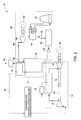
- the system 10 includes a gas turbine unit 12 including a compressor 14, a combustor 16, and a turbine 18.
- the compressor 14 is configured to receive ambient air at atmospheric pressure and to compress the air to a higher pressure.
- the compressed air is mixed with a gaseous or liquid fuel, for example natural gas, and combusted in the combustor 16.
- Combustion exhaust gas from the combustor 16 is expanded via the gas turbine 18.
- a generator 20 coupled to the turbine 18 transforms the mechanical energy into electrical power.
- the turbine 18 is coupled to a mechanical drive unit.
- the gas turbine 18 typically drives the compressor 14 via a shaft 22.
- the exhaust gas from the gas turbine 18 is optionally passed in heat exchange relationship with a cooling medium, for example feed-water, through a heat exchanger 24.
- the cooling medium is fed to the heat exchanger 24 through a feed line 26.
- cooling medium is heated to generate steam.
- one portion of the cooled exhaust gas is vented from the heat exchanger 24 to the atmosphere via a carbon dioxide capture unit 28 and a stack (not shown).
- pollutants may be toxic, for example, certain metals and polyaromatic hydrocarbons; sulfur oxides (SOx) such as sulfur dioxide (SO2), and nitrogen oxides (NOx); nitrogen dioxide and reactive organic gases; particulate matter; and greenhouse gases, notably carbon dioxide.
- NG natural gas
- Carbon dioxide can be "captured” or removed from the flue gas using methods including chemical or physical absorption, cryogenic fractionation, membrane separation, or the like.
- Another portion of the cooled exhaust gas is recirculated to the gas turbine unit 12. Flue gas recycling is used for example, to increase the carbon dioxide concentration in the exhaust gas stream and to reduce nitrogen oxide emissions.
- the other portion of the exhaust gas from the heat exchanger 24 is returned to an air inlet of the compressor 14 via a recirculation duct 30.
- the recirculated exhaust gas is mixed with the inlet air of the compressor 14.
- the duct 30 is provided with an exhaust gas recirculation cooler 31 configured to further cool the recirculated portion of the exhaust gas from the heat exchanger 24.
- the fuel is fed from a fuel source (not shown) to the combustor 16 via a separator 32 configured to separate sulfur content in the fuel so as to reduce sulfur content in the fuel before being fed to the combustor 16.
- the separator 32 is disposed upstream of the combustor 16.
- the sulfur content in the fuel may include but is not limited to hydrogen sulfide, sulfur dioxide, mercaptan, or the like.
- the separator 32 may separate sulfur content from the fuel using techniques including but not limited to membrane separation, absorption into a solvent, liquid phase oxidation, adsorption with a sorbent, or combinations thereof.
- the separator is configured to reduce the sulfur content to about 100 to 530 parts per billion by weight at a pressure in the range of about 10 to about 100 bars before being fed to the gas turbine unit 12.
- the sulfur content in the exhaust gas generated from the gas turbine unit 12 is about 30 parts per billion by weight when sulfur content in the fuel is reduced upstream of the combustor 16.
- the separator 32 reduces the amount of sulfur dioxide in the fuel from about 4043 parts per billion by weight to about 530 parts per billion by weight. If 40% of the exhaust gas is recirculated from the gas turbine 18 is recirculated to the inlet of the compressor 14, then the amount of sulfur dioxide in the exhaust gas recirculated to the compressor 14 may be around 24 parts per billion by weight, resulting in an inlet gas to the gas turbine compressor 14 with about 10 parts per billion weight.
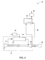
- an exemplary electric power generation system 10 configured to generate electric power is illustrated.
- the system 10 includes a combined cycle power generation system.
- the system 10 includes a gas turbine unit 12 including the compressor 14, the combustor 16, and the turbine 18.
- Combustion exhaust gas from the combustor 16 is expanded via the gas turbine 18.
- the generator 20 coupled to the turbine 18 transforms the mechanical energy into electrical power.
- the exhaust gas from the gas turbine 18 is passed in heat exchange relationship with a cooling medium e.g. feed-water through the heat exchanger 24 of a heat recovery unit 34 configured to produce additional power and increase plant efficiency.
- the heat exchanger 24 is a heat recovery steam boiler. As a result feed-water is heated to generate steam.
- One portion of cooled exhaust gas from the heat exchanger 24 is returned to an air inlet of the compressor 14 via the recirculation duct 30.
- the duct 30 may be provided with the exhaust gas recirculation cooler 31 configured to further cool the recirculated portion of the exhaust gas from the heat exchanger 24.
- the remaining portion of the cooled exhaust gas is vented from the heat exchanger 24 to the atmosphere via the carbon dioxide capture unit 28 and a stack (not shown).
- the steam from the heat exchanger 24 is fed to a steam turbine 36 via a pipe 38.
- the pipe 38 may be provided with a valve 40 configured to control the flow of steam through the pipe 38.
- the steam from the heat exchanger 24 is expanded via the steam turbine 36.
- a generator 42 coupled to the turbine 36 transforms the mechanical energy into electrical power.
- the steam exiting the steam turbine 36 passes through a condenser 44 where steam is transformed into water.
- the condenser 44 is cooled using water from a cooling unit, for example, a cooling tower 46 dissipating the steam's latent heat into the atmosphere.
- the condenser 44 may also be cooled using ambient air or any other cooling medium.
- the water from the condenser 44 is then passed through a feed pump 48, a deaerator 50, and another feed pump 52 to the heat exchanger 24.
- the pump 52 feeds the water to the heat exchanger 24 via the feedline 26.
- the heat recovery unit 34 includes a steam turbine unit; other types of heat recovery system are also envisaged.
- the fuel is fed from the fuel source (not shown) to the combustor 16 via the separator 32 configured to separate sulfur content in the fuel so as to reduce sulfur content in the fuel before being fed to the combustor 16.
- the separator 32 is disposed upstream of the combustor 16.
- the sulfur content in the fuel may include but is not limited to hydrogen sulfide, sulfur dioxide, mercaptan, or the like.
- the separator 32 may separate sulfur content from the fuel using techniques including but not limited to membrane separation, absorption into a solvent, liquid phase oxidation, adsorption with a sorbent, or combinations thereof. It should be noted herein that sulfur content may be removed from the fuel upstream of the combustor 16 by any separation process, for example, physical adsorption, chemical adsorption, using membranes, absorption, using differences in boiling point, or the like.
- the power generation system may include a simple cycle gas turbine provided with exhaust gas recirculation.
- the exhaust gas stream from the gas turbine 18 is not cooled via the heat exchanger 24 before being fed to the inlet of the compressor 14.
- the exhaust gas stream from the gas turbine 18 is recirculated to the inlet of the compressor 14 via the duct 30.
- the cooling of recirculated portion of the exhaust gas in the recirculation duct 30 is also optional.
- one portion of the exhaust gas from the gas turbine 18 is passed in heat exchange relationship with a cooling medium through the heat exchanger 24 and the remaining portion of the exhaust gas from the gas turbine 18 is returned to an air inlet of the compressor 14 via the recirculation duct 30.
- the system 10 includes a gas turbine unit 12 including the compressor 14, the combustor 16, and the turbine 18.
- the exhaust gas from the gas turbine 18 is passed in heat exchange relationship with a cooling medium e.g. feed-water through the heat exchanger 24.
- a cooling medium e.g. feed-water
- feed-water is heated to generate steam.
- the cooled exhaust gas is vented from the heat exchanger 24 to the atmosphere via the carbon dioxide capture unit 28 and a stack (not shown).
- the fuel is fed from the fuel source (not shown) to the combustor 16 via the separator 32 configured to separate sulfur content in the fuel so as to reduce sulfur content in the fuel before being fed to the combustor 16.
- the separator 32 is disposed upstream of the combustor 16.
- the system 10 does not include exhaust gas recirculation.
- the exhaust gas from the gas turbine 18 includes low sulfur content suitable for passing through the carbon dioxide capture unit 28.
- use of a separator prior to the combustor that removes sulphur content could be beneficial over conventional flue gas desulphurization methods which are used downstream of the power plant combustor.
Landscapes
- Engineering & Computer Science (AREA)
- Chemical & Material Sciences (AREA)
- Combustion & Propulsion (AREA)
- Mechanical Engineering (AREA)
- General Engineering & Computer Science (AREA)
- Life Sciences & Earth Sciences (AREA)
- Sustainable Development (AREA)
- Engine Equipment That Uses Special Cycles (AREA)
Applications Claiming Priority (1)
| Application Number | Priority Date | Filing Date | Title |
|---|---|---|---|
| US12/264,315 US20100107592A1 (en) | 2008-11-04 | 2008-11-04 | System and method for reducing corrosion in a gas turbine system |
Publications (1)
| Publication Number | Publication Date |
|---|---|
| EP2182194A2 true EP2182194A2 (fr) | 2010-05-05 |
Family
ID=41259863
Family Applications (1)
| Application Number | Title | Priority Date | Filing Date |
|---|---|---|---|
| EP09174285A Withdrawn EP2182194A2 (fr) | 2008-11-04 | 2009-10-28 | Système et procédé pour la réduction de corrosion dans une turbine à gaz |
Country Status (4)
| Country | Link |
|---|---|
| US (1) | US20100107592A1 (fr) |
| EP (1) | EP2182194A2 (fr) |
| JP (1) | JP2010112377A (fr) |
| CN (1) | CN101737168A (fr) |
Cited By (2)
| Publication number | Priority date | Publication date | Assignee | Title |
|---|---|---|---|---|
| EP2535101A1 (fr) * | 2011-06-13 | 2012-12-19 | Alstom Technology Ltd | Recirculation de gaz combustible avec membrane d'enrichissement en CO2 |
| US8899011B2 (en) | 2011-04-28 | 2014-12-02 | Knauf Gips Kg | Method and device for generating electricity and gypsum from waste gases containing hydrogen sulfide |
Families Citing this family (11)
| Publication number | Priority date | Publication date | Assignee | Title |
|---|---|---|---|---|
| US7942008B2 (en) * | 2006-10-09 | 2011-05-17 | General Electric Company | Method and system for reducing power plant emissions |
| US7870718B2 (en) * | 2007-11-14 | 2011-01-18 | General Electric Company | Purge system for an exhaust gas recirculation system |
| US7874141B2 (en) * | 2007-11-16 | 2011-01-25 | General Electric Company | Auxiliary fluid source for an EGR purge system |
| EP2636870B1 (fr) | 2012-03-05 | 2018-05-30 | General Electric Technology GmbH | Préparation de gaz d'échappement à partir d'une turbine à gaz pour la recirculation de gaz d'échappement |
| US20130239543A1 (en) * | 2012-03-16 | 2013-09-19 | Solar Turbine Incorporated | Gas turbine engine control system with gas monitor |
| US9086019B2 (en) * | 2012-07-02 | 2015-07-21 | United Technologies Corporation | Turbomachine thermal energy exchange |
| US9163561B2 (en) | 2012-10-29 | 2015-10-20 | General Electric Company | Power plant emissions reduction |
| US20140182305A1 (en) * | 2012-12-28 | 2014-07-03 | Exxonmobil Upstream Research Company | System and method for a turbine combustor |
| US11866182B2 (en) * | 2020-05-01 | 2024-01-09 | General Electric Company | Fuel delivery system having a fuel oxygen reduction unit |
| US11773776B2 (en) * | 2020-05-01 | 2023-10-03 | General Electric Company | Fuel oxygen reduction unit for prescribed operating conditions |
| IT202200014872A1 (it) * | 2022-07-15 | 2024-01-15 | Nuovo Pignone Tecnologie Srl | Plant for High-Efficiency Fuel to Mechanical Energy Conversion |
Family Cites Families (25)
| Publication number | Priority date | Publication date | Assignee | Title |
|---|---|---|---|---|
| US3703807A (en) * | 1971-01-15 | 1972-11-28 | Laval Turbine | Combined gas-steam turbine power plant |
| JPS5236610B2 (fr) * | 1974-05-09 | 1977-09-17 | ||
| US4202167A (en) * | 1979-03-08 | 1980-05-13 | Texaco Inc. | Process for producing power |
| US4267692A (en) * | 1979-05-07 | 1981-05-19 | Hydragon Corporation | Combined gas turbine-rankine turbine power plant |
| DE2945404C2 (de) * | 1979-11-09 | 1983-05-11 | Kraftwerk Union AG, 4330 Mülheim | Verfahren zum Betrieb einer kombinierten Gas-Dampfturbinenanlage und Gas-Dampfturbinenanlage zur Durchführung dieses Verfahrens |
| US4488866A (en) * | 1982-08-03 | 1984-12-18 | Phillips Petroleum Company | Method and apparatus for burning high nitrogen-high sulfur fuels |
| US5232467A (en) * | 1992-06-18 | 1993-08-03 | Texaco Inc. | Process for producing dry, sulfur-free, CH4 -enriched synthesis or fuel gas |
| US5794431A (en) * | 1993-07-14 | 1998-08-18 | Hitachi, Ltd. | Exhaust recirculation type combined plant |
| JP2954456B2 (ja) * | 1993-07-14 | 1999-09-27 | 株式会社日立製作所 | 排気再循環型コンバインドプラント |
| US5417052A (en) * | 1993-11-05 | 1995-05-23 | Midwest Research Institute | Hybrid solar central receiver for combined cycle power plant |
| JPH09256812A (ja) * | 1996-03-21 | 1997-09-30 | Toshiba Corp | コンバインドサイクル発電プラント |
| DE10028637A1 (de) * | 2000-06-09 | 2001-12-13 | Basf Ag | Verfahren zum Entsäuern eines Kohlenwasserstoff-Fluidstroms |
| JP3789070B2 (ja) * | 2000-06-16 | 2006-06-21 | 株式会社東芝 | ガスタービンシステムおよびその運転方法 |
| US6398851B1 (en) * | 2000-09-07 | 2002-06-04 | Ranendra K. Bose | Anti-air pollution & energy conservation system for automobiles using leaded or unleaded gasoline, diesel or alternate fuel |
| US6832485B2 (en) * | 2001-11-26 | 2004-12-21 | Ormat Industries Ltd. | Method of and apparatus for producing power using a reformer and gas turbine unit |
| US6809123B2 (en) * | 2002-08-07 | 2004-10-26 | Rentech, Inc. | Production of hydrogen and higher hydrocarbons |
| CA2406386C (fr) * | 2002-10-02 | 2004-05-18 | Westport Research Inc. | Methode et appareil de regeneration pour systemes d'adsorption de nox |
| EP1429000A1 (fr) * | 2002-12-09 | 2004-06-16 | Siemens Aktiengesellschaft | Procédé et dispositif pour l'opération d'une turbine à gaz avec une chambre de combustion du combustible fossilisé |
| DE10360951A1 (de) * | 2003-12-23 | 2005-07-28 | Alstom Technology Ltd | Wärmekraftanlage mit sequentieller Verbrennung und reduziertem CO2-Ausstoß sowie Verfahren zum Betreiben einer derartigen Anlage |
| DE102005015151A1 (de) * | 2005-03-31 | 2006-10-26 | Alstom Technology Ltd. | Gasturbinenanlage |
| US7909898B2 (en) * | 2006-02-01 | 2011-03-22 | Air Products And Chemicals, Inc. | Method of treating a gaseous mixture comprising hydrogen and carbon dioxide |
| US7637984B2 (en) * | 2006-09-29 | 2009-12-29 | Uop Llc | Integrated separation and purification process |
| US7856829B2 (en) * | 2006-12-15 | 2010-12-28 | Praxair Technology, Inc. | Electrical power generation method |
| US20080155984A1 (en) * | 2007-01-03 | 2008-07-03 | Ke Liu | Reforming system for combined cycle plant with partial CO2 capture |
| US9404418B2 (en) * | 2007-09-28 | 2016-08-02 | General Electric Company | Low emission turbine system and method |
-
2008
- 2008-11-04 US US12/264,315 patent/US20100107592A1/en not_active Abandoned
-
2009
- 2009-10-28 JP JP2009247161A patent/JP2010112377A/ja active Pending
- 2009-10-28 EP EP09174285A patent/EP2182194A2/fr not_active Withdrawn
- 2009-11-04 CN CN200910212259A patent/CN101737168A/zh active Pending
Cited By (3)
| Publication number | Priority date | Publication date | Assignee | Title |
|---|---|---|---|---|
| US8899011B2 (en) | 2011-04-28 | 2014-12-02 | Knauf Gips Kg | Method and device for generating electricity and gypsum from waste gases containing hydrogen sulfide |
| EP2535101A1 (fr) * | 2011-06-13 | 2012-12-19 | Alstom Technology Ltd | Recirculation de gaz combustible avec membrane d'enrichissement en CO2 |
| WO2012172405A1 (fr) * | 2011-06-13 | 2012-12-20 | Alstom Technology Ltd | Recirculation de gaz de carneau faisant intervenir une membrane d'enrichissement en co2 |
Also Published As
| Publication number | Publication date |
|---|---|
| US20100107592A1 (en) | 2010-05-06 |
| CN101737168A (zh) | 2010-06-16 |
| JP2010112377A (ja) | 2010-05-20 |
Similar Documents
| Publication | Publication Date | Title |
|---|---|---|
| EP2182194A2 (fr) | Système et procédé pour la réduction de corrosion dans une turbine à gaz | |
| EP2431579B1 (fr) | Système de centrale thermique multifonctions | |
| US8479489B2 (en) | Turbine exhaust recirculation | |
| JP5674281B2 (ja) | ガスタービンNOxの乾式三元触媒還元法 | |
| US20100018218A1 (en) | Power plant with emissions recovery | |
| TWI579507B (zh) | 利用廢氣再循環對富集之空氣進行化學計量燃燒之系統和方法 | |
| US20120023947A1 (en) | Systems and methods for co2 capture | |
| EP2208876A2 (fr) | Procédé permettant d'augmenter la quantité du dioxyde de carbone dans le gaz d'échappement d'une turbine et dispositif pour exécuter le procédé | |
| EP2724767A1 (fr) | Procédé de traitement d'un gaz de combustion riche en dioxyde de carbone et système de traitement de gaz de combustion | |
| JP2004530097A (ja) | Co2放出の少い発電機及び関連方法 | |
| RU2559467C2 (ru) | Способ снижения выбросов со2 в потоке газообразных продуктов сгорания и промышленные установки для осуществления этого способа | |
| US20120023892A1 (en) | Systems and methods for co2 capture | |
| JP2010190214A (ja) | 発電プラントにおける燃焼後加工 | |
| JP5448858B2 (ja) | 酸素燃焼発電プラントとその運転方法 | |
| Harkin et al. | Process integration analysis of a brown coal-fired power station with CO2 capture and storage and lignite drying | |
| JP2025521517A (ja) | 排気ガスの再循環を行う複合サイクル発電所 | |
| EP2108888A1 (fr) | Installation de capture de carbone et système de centrale électrique | |
| CN119186243B (zh) | 一种与燃煤锅炉耦合的固体钙基二氧化碳捕集系统及其方法 | |
| EP2530278A1 (fr) | Système et procédé de recirculation des gaz de combustion | |
| US20110146282A1 (en) | System and method for reducing sulfur compounds within fuel stream for turbomachine | |
| CN119678005A (zh) | 具有废气再循环的碳捕获系统和方法 | |
| RU2837807C2 (ru) | Система генерации электроэнергии, включающая в себя газовую турбину с теплоутилизационным парогенератором и улавливанием диоксида углерода, и способ | |
| JP2018096359A (ja) | 動力発生設備 | |
| CN119487288A (zh) | 具有废气再循环压缩机的发电站 | |
| CN120457566A (zh) | 具有燃料电池和碳捕获系统的燃烧系统 |
Legal Events
| Date | Code | Title | Description |
|---|---|---|---|
| PUAI | Public reference made under article 153(3) epc to a published international application that has entered the european phase |
Free format text: ORIGINAL CODE: 0009012 |
|
| AK | Designated contracting states |
Kind code of ref document: A2 Designated state(s): AT BE BG CH CY CZ DE DK EE ES FI FR GB GR HR HU IE IS IT LI LT LU LV MC MK MT NL NO PL PT RO SE SI SK SM TR |
|
| STAA | Information on the status of an ep patent application or granted ep patent |
Free format text: STATUS: THE APPLICATION IS DEEMED TO BE WITHDRAWN |
|
| 18D | Application deemed to be withdrawn |
Effective date: 20150501 |