EP2182277A2 - Structure d'isolation et de dissipation de chaleur d'une pièce électronique - Google Patents
Structure d'isolation et de dissipation de chaleur d'une pièce électronique Download PDFInfo
- Publication number
- EP2182277A2 EP2182277A2 EP09173999A EP09173999A EP2182277A2 EP 2182277 A2 EP2182277 A2 EP 2182277A2 EP 09173999 A EP09173999 A EP 09173999A EP 09173999 A EP09173999 A EP 09173999A EP 2182277 A2 EP2182277 A2 EP 2182277A2
- Authority
- EP
- European Patent Office
- Prior art keywords
- heat
- insulating
- housing
- dissipating
- electronic part
- Prior art date
- Legal status (The legal status is an assumption and is not a legal conclusion. Google has not performed a legal analysis and makes no representation as to the accuracy of the status listed.)
- Withdrawn
Links
Images




Classifications
-
- F—MECHANICAL ENGINEERING; LIGHTING; HEATING; WEAPONS; BLASTING
- F21—LIGHTING
- F21V—FUNCTIONAL FEATURES OR DETAILS OF LIGHTING DEVICES OR SYSTEMS THEREOF; STRUCTURAL COMBINATIONS OF LIGHTING DEVICES WITH OTHER ARTICLES, NOT OTHERWISE PROVIDED FOR
- F21V29/00—Protecting lighting devices from thermal damage; Cooling or heating arrangements specially adapted for lighting devices or systems
- F21V29/50—Cooling arrangements
- F21V29/56—Cooling arrangements using liquid coolants
- F21V29/58—Cooling arrangements using liquid coolants characterised by the coolants
-
- H—ELECTRICITY
- H05—ELECTRIC TECHNIQUES NOT OTHERWISE PROVIDED FOR
- H05K—PRINTED CIRCUITS; CASINGS OR CONSTRUCTIONAL DETAILS OF ELECTRIC APPARATUS; MANUFACTURE OF ASSEMBLAGES OF ELECTRICAL COMPONENTS
- H05K7/00—Constructional details common to different types of electric apparatus
- H05K7/20—Modifications to facilitate cooling, ventilating, or heating
-
- F—MECHANICAL ENGINEERING; LIGHTING; HEATING; WEAPONS; BLASTING
- F21—LIGHTING
- F21V—FUNCTIONAL FEATURES OR DETAILS OF LIGHTING DEVICES OR SYSTEMS THEREOF; STRUCTURAL COMBINATIONS OF LIGHTING DEVICES WITH OTHER ARTICLES, NOT OTHERWISE PROVIDED FOR
- F21V29/00—Protecting lighting devices from thermal damage; Cooling or heating arrangements specially adapted for lighting devices or systems
- F21V29/50—Cooling arrangements
- F21V29/70—Cooling arrangements characterised by passive heat-dissipating elements, e.g. heat-sinks
- F21V29/74—Cooling arrangements characterised by passive heat-dissipating elements, e.g. heat-sinks with fins or blades
- F21V29/76—Cooling arrangements characterised by passive heat-dissipating elements, e.g. heat-sinks with fins or blades with essentially identical parallel planar fins or blades, e.g. with comb-like cross-section
- F21V29/763—Cooling arrangements characterised by passive heat-dissipating elements, e.g. heat-sinks with fins or blades with essentially identical parallel planar fins or blades, e.g. with comb-like cross-section the planes containing the fins or blades having the direction of the light emitting axis
-
- F—MECHANICAL ENGINEERING; LIGHTING; HEATING; WEAPONS; BLASTING
- F21—LIGHTING
- F21V—FUNCTIONAL FEATURES OR DETAILS OF LIGHTING DEVICES OR SYSTEMS THEREOF; STRUCTURAL COMBINATIONS OF LIGHTING DEVICES WITH OTHER ARTICLES, NOT OTHERWISE PROVIDED FOR
- F21V29/00—Protecting lighting devices from thermal damage; Cooling or heating arrangements specially adapted for lighting devices or systems
- F21V29/50—Cooling arrangements
- F21V29/70—Cooling arrangements characterised by passive heat-dissipating elements, e.g. heat-sinks
- F21V29/80—Cooling arrangements characterised by passive heat-dissipating elements, e.g. heat-sinks with pins or wires
-
- F—MECHANICAL ENGINEERING; LIGHTING; HEATING; WEAPONS; BLASTING
- F21—LIGHTING
- F21V—FUNCTIONAL FEATURES OR DETAILS OF LIGHTING DEVICES OR SYSTEMS THEREOF; STRUCTURAL COMBINATIONS OF LIGHTING DEVICES WITH OTHER ARTICLES, NOT OTHERWISE PROVIDED FOR
- F21V29/00—Protecting lighting devices from thermal damage; Cooling or heating arrangements specially adapted for lighting devices or systems
- F21V29/85—Protecting lighting devices from thermal damage; Cooling or heating arrangements specially adapted for lighting devices or systems characterised by the material
- F21V29/86—Ceramics or glass
-
- F—MECHANICAL ENGINEERING; LIGHTING; HEATING; WEAPONS; BLASTING
- F28—HEAT EXCHANGE IN GENERAL
- F28D—HEAT-EXCHANGE APPARATUS, NOT PROVIDED FOR IN ANOTHER SUBCLASS, IN WHICH THE HEAT-EXCHANGE MEDIA DO NOT COME INTO DIRECT CONTACT
- F28D15/00—Heat-exchange apparatus with the intermediate heat-transfer medium in closed tubes passing into or through the conduit walls ; Heat-exchange apparatus employing intermediate heat-transfer medium or bodies
- F28D15/02—Heat-exchange apparatus with the intermediate heat-transfer medium in closed tubes passing into or through the conduit walls ; Heat-exchange apparatus employing intermediate heat-transfer medium or bodies in which the medium condenses and evaporates, e.g. heat pipes
-
- H—ELECTRICITY
- H10—SEMICONDUCTOR DEVICES; ELECTRIC SOLID-STATE DEVICES NOT OTHERWISE PROVIDED FOR
- H10W—GENERIC PACKAGES, INTERCONNECTIONS, CONNECTORS OR OTHER CONSTRUCTIONAL DETAILS OF DEVICES COVERED BY CLASS H10
- H10W40/00—Arrangements for thermal protection or thermal control
-
- H—ELECTRICITY
- H10—SEMICONDUCTOR DEVICES; ELECTRIC SOLID-STATE DEVICES NOT OTHERWISE PROVIDED FOR
- H10W—GENERIC PACKAGES, INTERCONNECTIONS, CONNECTORS OR OTHER CONSTRUCTIONAL DETAILS OF DEVICES COVERED BY CLASS H10
- H10W40/00—Arrangements for thermal protection or thermal control
- H10W40/10—Arrangements for heating
-
- H—ELECTRICITY
- H10—SEMICONDUCTOR DEVICES; ELECTRIC SOLID-STATE DEVICES NOT OTHERWISE PROVIDED FOR
- H10W—GENERIC PACKAGES, INTERCONNECTIONS, CONNECTORS OR OTHER CONSTRUCTIONAL DETAILS OF DEVICES COVERED BY CLASS H10
- H10W40/00—Arrangements for thermal protection or thermal control
- H10W40/70—Fillings or auxiliary members in containers or in encapsulations for thermal protection or control
-
- F—MECHANICAL ENGINEERING; LIGHTING; HEATING; WEAPONS; BLASTING
- F21—LIGHTING
- F21V—FUNCTIONAL FEATURES OR DETAILS OF LIGHTING DEVICES OR SYSTEMS THEREOF; STRUCTURAL COMBINATIONS OF LIGHTING DEVICES WITH OTHER ARTICLES, NOT OTHERWISE PROVIDED FOR
- F21V29/00—Protecting lighting devices from thermal damage; Cooling or heating arrangements specially adapted for lighting devices or systems
- F21V29/85—Protecting lighting devices from thermal damage; Cooling or heating arrangements specially adapted for lighting devices or systems characterised by the material
-
- F—MECHANICAL ENGINEERING; LIGHTING; HEATING; WEAPONS; BLASTING
- F21—LIGHTING
- F21Y—INDEXING SCHEME ASSOCIATED WITH SUBCLASSES F21K, F21L, F21S and F21V, RELATING TO THE FORM OR THE KIND OF THE LIGHT SOURCES OR OF THE COLOUR OF THE LIGHT EMITTED
- F21Y2115/00—Light-generating elements of semiconductor light sources
- F21Y2115/10—Light-emitting diodes [LED]
Definitions
- the present invention relates to an insulating and dissipating heat structure of an electronic part to solve the problem of high temperature for high power electronic parts, and more particularly to one which meets the safety requirements, without concerning about electric conduction and leakage.
- an electronic part will generate thermal energy when it is working. If the temperate of the electronic part is too high, it will influence the electricity and efficiency. Sometimes, the electronic part may be damaged or there is a fire accident. Accordingly, it is very important to dissipate heat for electronic parts.
- LED chips For the most popular LED chips, they transfer electric energy into light energy, accompanying with thermal energy. When the thermal energy becomes high, the light energy will be relatively decreased. The demand of dissipating heat for high power LED chips is more important. In order to ensure the safety when in use, the safety requirements are strict, without electric conduction and leakage.
- the primary object of the present invention is to provide an insulating and dissipating heat structure of an electronic part for lowering the temperature and dissipating heat.
- an insulating and dissipating heat structure of an electronic part comprising:
- the heat sink has a good heat conductivity to transfer the thermal energy from the electronic component.
- the heat sink has an inner surface provided with a plurality of cooling post or cooling fins.
- the housing is made of an insulating material, providing an insulation effect.
- the housing is filled with the fluid for cooling.
- the cooling posts (fins) of the heat sink extend into the housing to enhance the conduction of the thermal energy from the electronic component.
- the cooling posts (fins) of the heat sink are used to increase the surface area for dissipating heat efficiently.
- the housing is further provided with a heat dissipating device.
- the heat dissipating device is to assist in transferring the thermal energy outwardly.
- the fluid and the housing are in an insulating status to ensure the safety, without electric conduction and leakage.
- the advantage of the present invention is that the heat sink is attached to one surface of the electronic component and coupled to the first notch of the housing; the housing is hollow inside and filled with the fluid for cooling; the housing is made of an insulating material; the heat sink, the fluid, and the housing are able to lower the temperate and dissipate heat.
- the housing has the character of insulation to meet the safety requirements of high power electronic parts, without concerning about electric conduction and leakage.
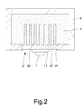
- a first preferred embodiment of the present invention comprises an electronic component 1, a heat sink 2, a housing 3 and fluid 4.
- the electronic component 1 is a light emitting diode, a power transistor, or other electronic component which will generate thermal energy.
- the electronic component 1 is provided with a heat conductor 11 or integrally formed with a circuit basal plate.
- the heat sink 2 is attached to one surface of the electronic component 1.
- the heat sink 2 is made of metal, carbon fiber, composite material or the like which conducts heat efficiently so as to efficiently conduct and dissipate thermal energy from the electronic component 1.
- the heat sink 2 comprises a heat conducting member 21 and a plurality of cooling posts 22 (or cooling fins).
- the heat conducting member 21 is attached to the heat conductor 11 or the circuit basal plate for transferring thermal energy.
- the cooling posts 22 are disposed on an inner surface of the heat conducting member 21 for increasing the surface area to dissipate heat and transferring the heat energy to the surrounding.
- the housing 3 is made of glass, plastics, synthetic resin, ceramic, composite material or the like which is insulating and capable of heat conduction.
- the housing 3 is hollow inside and has a first notch for coupling with the heat conducting member 21 of the heat sink 2.
- the fluid 4 is filled in the housing 3, which is preferably capable of heat dissipation, cooling, and heat conduction.
- the fluid 4 can be water, cooling fluid, lower concentration oil, solvent, surfactant or the like.
- the fluid 4 is used to transfer the thermal energy from the electronic component 1 and the heat sink 2 to the housing 3 so as to dissipate heat and lower the temperature.
- the thermal energy will be quickly transferred to the fluid 4 through the heat sink 2.
- the fluid 4 is adapted to dissipate partial thermal energy, and then the housing 3 transfers the thermal energy outwardly to lower the temperature.
- the housing 3 is made of an insulating material. Thus, there is no need to concern the problem of current leakage.
- the heat sink 2 is coupled to the first notch 31 in the way of heat fusion, screw connection, or adhesive for engagement and seal.
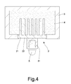
- Fig. 3 and Fig. 4 show a second preferred embodiment of the present invention, which is substantially similar to the first preferred embodiment except the form of an electronic component 5.
- the electronic component 5 is substantially in an upright shape and also has a heat conductor 51 which is attached to the heat conducting member 21 for conducting thermal energy.
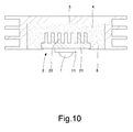
- Fig. 5 and Fig. 6 show a third preferred embodiment of the present invention, which is substantially similar to the first and second preferred embodiments with the exceptions described hereinafter.
- the housing 3 is formed with a second notch 32 for receiving a heat dissipating device 6.
- the heat dissipating device 6 is made of metal, carbon fiber, composite material or the like which conducts heat efficiently so as to efficiently conduct and dissipate the thermal energy of the fluid 4 outwardly.
- the heat dissipating device 6 is provided with cooling posts or cooling fins 61, 62 inside and outside. In this embodiment, the fluid 4 must be insulating fluid to ensure insulation.
- the thermal energy will be quickly transferred to the fluid 4 through the heat sink 2.
- the housing 3 and the heat dissipating device 6 are used to transfer the thermal energy outwardly to lower the temperature.
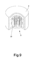
- Fig. 7 and Fig. 8 show a fourth preferred embodiment of the present invention.
- the housing 3 is in a circular shape.
- the electronic component 1 is a light emitting diode chip, and may be provided with a lampshade 7 at a front end thereof, if necessary.
- the lampshade 7 is made of transparent glass, translucent glass, misty glass or a material which is pervious to light. Thus, the light is comfortable and not harsh to the eye. Furthermore, the lampshade 7 can be colored as desired for matching different places.
- the heat sink 2 and the housing 3 can be made in a round shape or other shapes.
- insulating member 8 located between the heat sink 2 and the housing 3.
- the insulating member 8 is made of nonconductive material, such as glass, plastics, synthetic resin, ceramic, composite material or the like.
- the insulating member 8 provides a nonconductive action between the heat sink 2 and the housing 3.
- the housing 3 may be made of not insulating material.
- the fluid 4 must be insulating.
Landscapes
- Engineering & Computer Science (AREA)
- General Engineering & Computer Science (AREA)
- Physics & Mathematics (AREA)
- Ceramic Engineering (AREA)
- Chemical & Material Sciences (AREA)
- Thermal Sciences (AREA)
- Life Sciences & Earth Sciences (AREA)
- Sustainable Development (AREA)
- Mechanical Engineering (AREA)
- Microelectronics & Electronic Packaging (AREA)
- Cooling Or The Like Of Electrical Apparatus (AREA)
- Cooling Or The Like Of Semiconductors Or Solid State Devices (AREA)
- Led Device Packages (AREA)
Applications Claiming Priority (1)
| Application Number | Priority Date | Filing Date | Title |
|---|---|---|---|
| TW097142339A TW201019431A (en) | 2008-11-03 | 2008-11-03 | Insulating and heat-dissipating structure of an electronic component |
Publications (2)
| Publication Number | Publication Date |
|---|---|
| EP2182277A2 true EP2182277A2 (fr) | 2010-05-05 |
| EP2182277A3 EP2182277A3 (fr) | 2011-11-30 |
Family
ID=41650355
Family Applications (1)
| Application Number | Title | Priority Date | Filing Date |
|---|---|---|---|
| EP09173999A Withdrawn EP2182277A3 (fr) | 2008-11-03 | 2009-10-26 | Structure d'isolation et de dissipation de chaleur d'une pièce électronique |
Country Status (6)
| Country | Link |
|---|---|
| US (1) | US20100110636A1 (fr) |
| EP (1) | EP2182277A3 (fr) |
| JP (1) | JP5109174B2 (fr) |
| KR (1) | KR101168112B1 (fr) |
| CA (1) | CA2682594C (fr) |
| TW (1) | TW201019431A (fr) |
Cited By (3)
| Publication number | Priority date | Publication date | Assignee | Title |
|---|---|---|---|---|
| WO2012034332A1 (fr) * | 2010-09-15 | 2012-03-22 | Yang Dongzuo | Structure de del d'une seule pièce comportant un équipement de refroidissement |
| DE102011052722B3 (de) * | 2011-08-16 | 2012-08-09 | Alunatec | Anordnung eines Kühlkörpers sowie eines elektronischen Bauteils |
| WO2018050144A1 (fr) * | 2016-09-19 | 2018-03-22 | Hytecon Ag | Dispositif décentralisé de désinfection d'eau |
Families Citing this family (18)
| Publication number | Priority date | Publication date | Assignee | Title |
|---|---|---|---|---|
| US20120250333A1 (en) * | 2009-10-26 | 2012-10-04 | Wen-Chiang Chou | Insulating and Dissipating Heat Structure of an Electronic Part |
| CN102401358B (zh) * | 2010-09-10 | 2016-08-03 | 欧司朗股份有限公司 | 冷却体的制造方法、冷却体以及具有该冷却体的照明装置 |
| US8728240B2 (en) * | 2012-05-02 | 2014-05-20 | Msp Corporation | Apparatus for vapor condensation and recovery |
| US9267659B2 (en) * | 2012-05-14 | 2016-02-23 | Sl Corporation | Vehicle lamp |
| CN102927484B (zh) * | 2012-11-26 | 2013-11-20 | 殷逢宝 | 一种大功率led灯具 |
| KR101519717B1 (ko) | 2013-08-06 | 2015-05-12 | 현대자동차주식회사 | 전자 제어 유닛용 방열 장치 |
| CN104654105A (zh) * | 2013-11-19 | 2015-05-27 | 鸿富锦精密工业(深圳)有限公司 | Led路灯 |
| WO2016026695A1 (fr) * | 2014-08-21 | 2016-02-25 | Philips Lighting Holding B.V. | Dispositif émetteur de lumière |
| TWI535972B (zh) * | 2014-11-26 | 2016-06-01 | 中強光電股份有限公司 | 車用照明裝置 |
| CN105114919B (zh) * | 2015-08-11 | 2018-02-13 | 电子科技大学 | 一种采用石蜡及水冷的散热装置 |
| CN105336831A (zh) * | 2015-09-24 | 2016-02-17 | 李峰 | 一种液体填充式led灯 |
| CN105351901B (zh) * | 2015-12-12 | 2018-10-16 | 重庆信德电子有限公司 | 循环水式散热装置 |
| JP7172579B2 (ja) * | 2018-12-26 | 2022-11-16 | トヨタ自動車株式会社 | 電気機器 |
| WO2021111296A1 (fr) * | 2019-12-06 | 2021-06-10 | 3M Innovative Properties Company | Conception à motifs pour la gestion thermique d'un système de refroidissement par immersion diphasique pour l'électronique |
| EP4092720A1 (fr) * | 2021-05-20 | 2022-11-23 | Aptiv Technologies Limited | Dissipateur de chaleur |
| US11655974B2 (en) * | 2021-06-11 | 2023-05-23 | Eaton Intelligent Power Limited | Composite fin heat sink |
| JP2022190987A (ja) * | 2021-06-15 | 2022-12-27 | 株式会社フジクラ | コールドプレート |
| CN115424991B (zh) * | 2022-08-08 | 2025-09-02 | 华为数字能源技术有限公司 | 功率模组、逆变器与车辆 |
Citations (1)
| Publication number | Priority date | Publication date | Assignee | Title |
|---|---|---|---|---|
| JP2005062419A (ja) * | 2003-08-11 | 2005-03-10 | Seiko Epson Corp | 光源装置 |
Family Cites Families (17)
| Publication number | Priority date | Publication date | Assignee | Title |
|---|---|---|---|---|
| US4012770A (en) * | 1972-09-28 | 1977-03-15 | Dynatherm Corporation | Cooling a heat-producing electrical or electronic component |
| US5006924A (en) * | 1989-12-29 | 1991-04-09 | International Business Machines Corporation | Heat sink for utilization with high density integrated circuit substrates |
| US5000256A (en) * | 1990-07-20 | 1991-03-19 | Minnesota Mining And Manufacturing Company | Heat transfer bag with thermal via |
| US5629840A (en) * | 1992-05-15 | 1997-05-13 | Digital Equipment Corporation | High powered die with bus bars |
| US5485671A (en) * | 1993-09-10 | 1996-01-23 | Aavid Laboratories, Inc. | Method of making a two-phase thermal bag component cooler |
| US5411077A (en) * | 1994-04-11 | 1995-05-02 | Minnesota Mining And Manufacturing Company | Flexible thermal transfer apparatus for cooling electronic components |
| US6055154A (en) * | 1998-07-17 | 2000-04-25 | Lucent Technologies Inc. | In-board chip cooling system |
| JP2005045062A (ja) * | 2003-07-23 | 2005-02-17 | Seiko Epson Corp | 光源装置及びそれを用いた投射型表示装置 |
| US20050047140A1 (en) * | 2003-08-25 | 2005-03-03 | Jung-Chien Chang | Lighting device composed of a thin light emitting diode module |
| US7002247B2 (en) * | 2004-06-18 | 2006-02-21 | International Business Machines Corporation | Thermal interposer for thermal management of semiconductor devices |
| US20060196640A1 (en) * | 2004-12-01 | 2006-09-07 | Convergence Technologies Limited | Vapor chamber with boiling-enhanced multi-wick structure |
| JP2006310363A (ja) * | 2005-04-26 | 2006-11-09 | Toshiba Corp | パワー半導体装置 |
| US20070159828A1 (en) * | 2006-01-09 | 2007-07-12 | Ceramate Technical Co., Ltd. | Vertical LED lamp with a 360-degree radiation and a high cooling efficiency |
| US7784972B2 (en) * | 2006-12-22 | 2010-08-31 | Nuventix, Inc. | Thermal management system for LED array |
| JP2008243780A (ja) * | 2007-03-29 | 2008-10-09 | Tamkang Univ | ヒートパイプのある熱放散モジュールを組み込まれる高出力led照明組品 |
| US20090001372A1 (en) * | 2007-06-29 | 2009-01-01 | Lumination Llc | Efficient cooling of lasers, LEDs and photonics devices |
| US20090059594A1 (en) * | 2007-08-31 | 2009-03-05 | Ming-Feng Lin | Heat dissipating apparatus for automotive LED lamp |
-
2008
- 2008-11-03 TW TW097142339A patent/TW201019431A/zh not_active IP Right Cessation
-
2009
- 2009-10-20 CA CA2682594A patent/CA2682594C/fr not_active Expired - Fee Related
- 2009-10-22 KR KR1020090100708A patent/KR101168112B1/ko not_active Expired - Fee Related
- 2009-10-22 JP JP2009243618A patent/JP5109174B2/ja not_active Expired - Fee Related
- 2009-10-26 US US12/605,680 patent/US20100110636A1/en not_active Abandoned
- 2009-10-26 EP EP09173999A patent/EP2182277A3/fr not_active Withdrawn
Patent Citations (1)
| Publication number | Priority date | Publication date | Assignee | Title |
|---|---|---|---|---|
| JP2005062419A (ja) * | 2003-08-11 | 2005-03-10 | Seiko Epson Corp | 光源装置 |
Cited By (3)
| Publication number | Priority date | Publication date | Assignee | Title |
|---|---|---|---|---|
| WO2012034332A1 (fr) * | 2010-09-15 | 2012-03-22 | Yang Dongzuo | Structure de del d'une seule pièce comportant un équipement de refroidissement |
| DE102011052722B3 (de) * | 2011-08-16 | 2012-08-09 | Alunatec | Anordnung eines Kühlkörpers sowie eines elektronischen Bauteils |
| WO2018050144A1 (fr) * | 2016-09-19 | 2018-03-22 | Hytecon Ag | Dispositif décentralisé de désinfection d'eau |
Also Published As
| Publication number | Publication date |
|---|---|
| JP2010109368A (ja) | 2010-05-13 |
| TW201019431A (en) | 2010-05-16 |
| TWI371094B (fr) | 2012-08-21 |
| KR20100049485A (ko) | 2010-05-12 |
| CA2682594C (fr) | 2014-05-13 |
| CA2682594A1 (fr) | 2010-05-03 |
| US20100110636A1 (en) | 2010-05-06 |
| EP2182277A3 (fr) | 2011-11-30 |
| JP5109174B2 (ja) | 2012-12-26 |
| KR101168112B1 (ko) | 2012-07-24 |
Similar Documents
| Publication | Publication Date | Title |
|---|---|---|
| CA2682594C (fr) | Dissipateur thermique de composant electronique avec isolant | |
| US20120250333A1 (en) | Insulating and Dissipating Heat Structure of an Electronic Part | |
| TWI476347B (zh) | 照明裝置(三) | |
| EP2748513B1 (fr) | Dispositif d'éclairage | |
| US20140043815A1 (en) | Light emitting diode bulb structure for enhancing heat dissipation efficiency | |
| CN101784176A (zh) | 电子零件的绝缘散热结构 | |
| US20130088880A1 (en) | Led lighting device | |
| TW201250161A (en) | Omni-directional channeling of liquids for passive convection in LED bulbs | |
| KR101080700B1 (ko) | 조명 장치 | |
| US20130328474A1 (en) | Omni-directional channeling of liquids for passive convection in led bulbs | |
| CN101911400A (zh) | 具有至少一个电子元件的适配器 | |
| US8998459B2 (en) | Illuminating apparatus | |
| WO2011137355A1 (fr) | Structure de refroidissement pour lampes à del | |
| US20080298075A1 (en) | Lamp holder structure | |
| US8847472B1 (en) | Laminate support structure for an LED in a liquid-filled bulb | |
| EP3193081A1 (fr) | Module de diodes électroluminescentes et écran | |
| JP2016025088A (ja) | 発光ダイオード電球 | |
| CN204592939U (zh) | Led管灯 | |
| KR101304874B1 (ko) | 조명 장치 | |
| KR102062086B1 (ko) | 조명 장치 | |
| CN201066110Y (zh) | 散热结构以及led灯泡的散热结构 | |
| CN207762600U (zh) | 一种led光组件单体 | |
| KR102062087B1 (ko) | 조명 장치 | |
| KR20140107860A (ko) | 조명 장치 | |
| CN202598176U (zh) | 灯管式发光装置 |
Legal Events
| Date | Code | Title | Description |
|---|---|---|---|
| PUAI | Public reference made under article 153(3) epc to a published international application that has entered the european phase |
Free format text: ORIGINAL CODE: 0009012 |
|
| AK | Designated contracting states |
Kind code of ref document: A2 Designated state(s): AT BE BG CH CY CZ DE DK EE ES FI FR GB GR HR HU IE IS IT LI LT LU LV MC MK MT NL NO PL PT RO SE SI SK SM TR |
|
| AX | Request for extension of the european patent |
Extension state: AL BA RS |
|
| PUAL | Search report despatched |
Free format text: ORIGINAL CODE: 0009013 |
|
| AK | Designated contracting states |
Kind code of ref document: A3 Designated state(s): AT BE BG CH CY CZ DE DK EE ES FI FR GB GR HR HU IE IS IT LI LT LU LV MC MK MT NL NO PL PT RO SE SI SK SM TR |
|
| AX | Request for extension of the european patent |
Extension state: AL BA RS |
|
| RIC1 | Information provided on ipc code assigned before grant |
Ipc: F21Y 101/02 20060101ALN20111026BHEP Ipc: F21V 29/00 20060101AFI20111026BHEP |
|
| 17P | Request for examination filed |
Effective date: 20120524 |
|
| 17Q | First examination report despatched |
Effective date: 20160624 |
|
| STAA | Information on the status of an ep patent application or granted ep patent |
Free format text: STATUS: THE APPLICATION IS DEEMED TO BE WITHDRAWN |
|
| 18D | Application deemed to be withdrawn |
Effective date: 20171130 |
|
| RIC1 | Information provided on ipc code assigned before grant |
Ipc: F21Y 101/02 20000101ALN20111026BHEP Ipc: F21V 29/00 20150101AFI20111026BHEP |