EP2182329B1 - Encodeur rotatif de détection par induction - Google Patents
Encodeur rotatif de détection par induction Download PDFInfo
- Publication number
- EP2182329B1 EP2182329B1 EP09174358.3A EP09174358A EP2182329B1 EP 2182329 B1 EP2182329 B1 EP 2182329B1 EP 09174358 A EP09174358 A EP 09174358A EP 2182329 B1 EP2182329 B1 EP 2182329B1
- Authority
- EP
- European Patent Office
- Prior art keywords
- rotor
- winding
- rotation
- spindle
- stator
- Prior art date
- Legal status (The legal status is an assumption and is not a legal conclusion. Google has not performed a legal analysis and makes no representation as to the accuracy of the status listed.)
- Active
Links
Images




Classifications
-
- G—PHYSICS
- G01—MEASURING; TESTING
- G01D—MEASURING NOT SPECIALLY ADAPTED FOR A SPECIFIC VARIABLE; ARRANGEMENTS FOR MEASURING TWO OR MORE VARIABLES NOT COVERED IN A SINGLE OTHER SUBCLASS; TARIFF METERING APPARATUS; MEASURING OR TESTING NOT OTHERWISE PROVIDED FOR
- G01D5/00—Mechanical means for transferring the output of a sensing member; Means for converting the output of a sensing member to another variable where the form or nature of the sensing member does not constrain the means for converting; Transducers not specially adapted for a specific variable
- G01D5/12—Mechanical means for transferring the output of a sensing member; Means for converting the output of a sensing member to another variable where the form or nature of the sensing member does not constrain the means for converting; Transducers not specially adapted for a specific variable using electric or magnetic means
- G01D5/14—Mechanical means for transferring the output of a sensing member; Means for converting the output of a sensing member to another variable where the form or nature of the sensing member does not constrain the means for converting; Transducers not specially adapted for a specific variable using electric or magnetic means influencing the magnitude of a current or voltage
- G01D5/20—Mechanical means for transferring the output of a sensing member; Means for converting the output of a sensing member to another variable where the form or nature of the sensing member does not constrain the means for converting; Transducers not specially adapted for a specific variable using electric or magnetic means influencing the magnitude of a current or voltage by varying inductance, e.g. by a movable armature
- G01D5/2006—Mechanical means for transferring the output of a sensing member; Means for converting the output of a sensing member to another variable where the form or nature of the sensing member does not constrain the means for converting; Transducers not specially adapted for a specific variable using electric or magnetic means influencing the magnitude of a current or voltage by varying inductance, e.g. by a movable armature by influencing the self-induction of one or more coils
- G01D5/2013—Mechanical means for transferring the output of a sensing member; Means for converting the output of a sensing member to another variable where the form or nature of the sensing member does not constrain the means for converting; Transducers not specially adapted for a specific variable using electric or magnetic means influencing the magnitude of a current or voltage by varying inductance, e.g. by a movable armature by influencing the self-induction of one or more coils by a movable ferromagnetic element, e.g. a core
Definitions
- the present invention relates to an induction detecting rotary encoder that measures an angle of rotation of an object by using flux coupling of wires provided between a rotor and a stator.
- An induction detecting rotary encoder has a stator and a rotor, the stator being provided with transmitting windings and receiving windings, the rotor being provided with flux coupling windings which are flux coupled with the transmitting windings and receiving windings (refer to Japanese Patent Laid-open Publication No. H10-213407 , for example). With demands for downsizing a micrometer and the like on which the rotary encoder is mounted and for achieving high accuracy, it is required to further reduce a pitch of the receiving windings.
- a rotary encoder having two tracks has problems below. Specifically, accuracy of the two tracks needs to be improved simultaneously in order to enhance accuracy of the rotary encoder. Further, a tolerance is limited for absolute position measurement over an entire measurement range. When the tolerance is increased, the accuracy of the rotary encoder is deteriorated.
- the present invention provides a highly accurate induction detecting rotary encoder capable of measuring an absolute position.
- the induction detecting rotary encoder includes a stator; a first rotor engaged with a rotatable shaft, rotated along with the rotating shaft, and provided axially opposite to the stator; a second rotor provided on an external periphery side of the first rotor, rotatable with respect to the first rotor, and axially opposite to the stator; a rotation transferer adapted for transferring rotation of the rotating shaft and rotating the second rotor at a speed different from the first rotor; a first transmitting winding, a second transmitting winding, and a third transmitting winding provided in order from inside concentrically to the rotating shaft, on a surface of the stator opposite to the first rotor and the second rotor; a first receiving winding, a second receiving winding, and a third receiving winding provided in order from inside concentrically to the rotating shaft, on the surface of the stator opposite to the first rotor and the second rotor, and associated with the first transmitting
- the first transmitting winding, the first receiving winding, and the first flux coupling body constitute a first angle detection track generating a cyclic change for N 1 times per single rotation of the first rotor.
- the second transmitting winding, the second receiving winding, and the second flux coupling body constitute a second angle detection track generating a cyclic change for N 2 times per single rotation of the first rotor.
- the third transmitting winding, the third receiving winding, and the third flux coupling body constitute a third angle detection track generating a cyclic change for N 3 times per single rotation of the second rotor.
- N 1 , N 2 , and N 3 are different from one another, and N 3 is less than N 1 and N 2 .
- the present invention can provide a highly accurate induction detecting rotary encoder capable of measuring an absolute position.
- FIG. 1 is a cross-sectional view illustrating the micrometer head 1 according to the first embodiment.
- the micrometer head 1 has a main body 2, a spindle 3 extending from the main body 2, and an induction detecting rotary encoder 4 provided centering around the spindle 3.
- the micrometer head 1 further has a transmission/reception controller 6, a computation processor 7, and a display 8.
- the transmission/reception controller 6 controls transmission and reception to and from the induction detecting rotary encoder 4.
- the computation processor 7 executes a computation process based on a signal from the transmission/reception controller 6 (induction detecting rotary encoder 4).
- the display 8 displays a computation result provided by the computation processor 7.
- the main body 2 has a substantially cylindrical shape, in which housing spaces 21 and 22 are provided.
- the housing spaces 21 and 22 are partitioned by a partitioning plate 23.
- Bores 24 and 25 are provided, through which the spindle 3 is passed, the bore 24 being provided to a wall on a front side (left side in the drawing) of the spindle of the substantially cylindrical main body 2, the bore 25 being provided to the partitioning plate 23.
- a male thread 26 is provided to an end portion of a base end side (right side in the drawing) of the main body 2.
- the bores 24 and 25 and the male thread 26 are provided concentrically.
- the spindle 3 has a substantially column shape.
- the spindle 3 has a contact surface 31 in a front end portion and a knob 32 in a base end portion, the contact surface 31 being contacted with an object to be measured (not shown in the drawing).
- the knob 32 is provided to externally rotate the spindle 3.
- the spindle 3 is inserted through the bores 24 and 25 of the main body 2. Both end portions of the spindle 3 are projected from the main body 2.
- a lead thread 33 which is provided to an external periphery of the spindle 3, is screwed into and engaged with the male thread 26 of the main body 2.
- the lead thread 33 which is formed for 40 rotations at a pitch of 0.5 mm, for example, can protract and retract the spindle 3 for a length of 20 mm.
- a linear key groove 34 is provided axially in a substantially middle portion of the spindle 3.
- Fig. 2 is a perspective view of the induction detecting rotary encoder 4.
- Fig. 3 is an exploded perspective view of the induction detecting rotary encoder 4.
- the induction detecting rotary encoder 4 has a first rotary encoder 40 and a second rotary encoder 50, and is housed in the housing space 22 of the main body 2.
- the first rotary encoder 40 has a stator 41, a first rotor 42, and a first rotating cylinder 43.
- the stator 41 has an insertion hole 44 at the center of a circular plate thereof, through which the spindle 3 is inserted.
- the stator 41 is fixed to the partitioning plate 23.
- the stator 41 is externally fitted to an insulating member 27, which is provided around the bore 25 of the partitioning plate 23.
- the first rotor 42 has an insertion hole 45 at the center of a circular plate thereof, through which the spindle 3 is inserted.
- the first rotor 42 is provided at a predetermined distance from the stator 41 and provided axially opposite to the stator 41.
- the first rotating cylinder 43 When the spindle 3 is inserted through the first rotating cylinder 43, the first rotating cylinder 43 is provided more to the front side of the spindle 3 than the stator 41, and rotatably supports the first rotor 42 around the shaft of the spindle 3. Specifically, a rotor supporter 46 is provided along the external periphery of the spindle 3 at the end portion on the stator 41 side of the first rotating cylinder 43. The first rotor 42 is externally fitted to an external periphery of the rotor supporter 46.
- the first rotating cylinder 43 is provided with a screw-type key 47, which is screwed toward the center from the external periphery. An end portion of the key 47 is projected from an inner periphery of the first rotating cylinder 43, and is engaged with the key groove 34 of the spindle 3. Specifically, when the spindle 3 is rotated, the first rotating cylinder 43 is rotated in synchronization with the spindle 3, since the key 47 is engaged with the key groove 34 of spindle 3.
- a first gear 48 is provided on the external periphery of the first rotating cylinder 43.
- the gear 48 is provided to the first rotating cylinder 43 in the end portion on the front side of the spindle 3.
- the gear 48 has a larger external diameter than that of other portions of the rotating cylinder 43.
- the first gear 48 has 40 teeth, for instance.
- the second rotary encoder 50 has the above-described stator 41, a second rotor 51, a second rotating cylinder (holding body) 52, and a relay gear 53.
- the stator 41 is the stator 41 of the first rotary encoder 40, and is a common part for the rotary encoders 40 and 50.
- the second rotor 51 has a hole 54 at the center of a circular plate thereof, in which the first rotor 42 can be disposed.
- the second rotor 51 is thus provided surrounding the first rotor 42 on an external periphery thereof. Similar to the first rotor 42, the second rotor 51 is provided at a predetermined distance from the stator 41 and provided axially opposite to the stator 41. As described above, the surfaces of the rotor 42 and 51, which are provided opposite to the stator 41, are provided substantially flush.
- the second rotating cylinder 52 When the first rotating cylinder 43 (a portion excluding the first gear 48) is inserted into the second rotating cylinder 52, the second rotating cylinder 52 is supported by the first rotating cylinder 43.
- the second rotor 51 is attached to the second rotating cylinder 52 in an end portion thereof on the stator 41 side.
- the second rotor 51 is thus rotatably supported around the shaft of the spindle 3.
- a bicylindrical configuration is provided having the first rotary encoder 40 inside and the second rotary encoder 50 outside.
- a second gear 55 is provided on an external periphery of the second rotating cylinder 52.
- the gear 55 is provided to the rotating cylinder 52 in an end portion thereof on the front side of the spindle 3.
- the gear 55 has a substantially same external diameter as that of the gear 48 of the first rotating cylinder 43.
- the second gear 55 has 41 teeth, for instance, and thus has one tooth more than the first gear 48.
- the relay gear 53 is rotatably supported by the main body 2 and is engaged with both the first gear 48 and the second gear 55.
- the relay gear 53 has a first relay gear 53A engaging with the first gear 48, a second relay gear 53B engaging with the second gear 55, and a shaft 53C concentrically supporting the relay gears 53A and 53B.
- the relay gears 53A and 53B have the same number of teeth of, for example, 12. Modules coincide for the first gear 48 and the first relay gear 53A, which constitute a first pair of gears. Modules coincide for the second gear 55 and the second relay gear 53B, which constitute a second pair of gears.
- rotating the first rotating cylinder 43 can smoothly rotate the second rotating cylinder 52 by way of the relay gear 53.
- the rotors 42 and 51 are rotated at different speeds because of the difference in the number of teeth of the gear 48 and the gear 55.
- the gear 48 has 40 teeth and the gear 55 has 41 teeth as in the present embodiment, for example, the first rotor 42 is rotated 40 times and the second rotor 51 is rotated 39 times while the spindle 3 is rotated 40 times within a range of protraction and retraction movement.
- first rotary encoder 40 and the second rotary encoder 50 can detect an absolute angle within one rotation of the rotor 42 and the rotor 51, respectively.
- the stator 41 outputs a phase signal indicating change in one cycle per rotation of the first rotor 42. Since the first rotor 42 is rotated in synchronization with the spindle 3, the phase signal associated with the first rotor 42 indicates a first cycle change of the present invention in accordance with one rotation of the spindle 3. For instance, while the spindle 3 is rotated 40 times, 40 cycle changes are indicated.
- the stator 41 also outputs a phase signal indicating change in one cycle per rotation of the second rotor 51. Since the second rotor 51 is rotated 39 times while the spindle 3 is rotated 40 times, the phase signal associated with the second rotor 51 indicates 39 cycle changes in accordance with 40 rotations of the spindle 3.
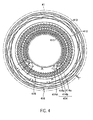
- Fig. 4 illustrates a configuration on the stator 41.
- Fig. 5 illustrates a configuration on the first rotor 42 and the second rotor 51.
- a first transmitting winding 411, a second transmitting winding 412, and a third transmitting winding 413 are provided concentrically to the spindle 3, on the stator 41 opposing the first rotor 42 and the second rotor 51.
- the first transmitting winding 411 has a substantially circular shape having a first radius from the spindle 3 (rotating shaft).
- the second transmitting winding 412 has a substantially circular shape having a second radius from the spindle 3 (rotating shaft), the second radius being larger than the first radius.
- the third transmitting winding 413 has a substantially circular shape having a third radius from the spindle 3 (rotating shaft), the third radius being larger than the second radius.
- a first receiving winding 414, a second receiving winding 415, and a third receiving winding 416 are provided concentrically to the spindle 3, on the stator 41 opposing the first rotor 42 and the second rotor 51.
- the first to third receiving windings 414 to 416 are provided, such that a distance from the spindle 3 (rotating shaft) changes periodically.
- the first receiving winding 414 is provided between the first transmitting winding 411 and the second transmitting winding 412 on the first transmitting winding 411 side.
- the second receiving winding 415 is provided between the first transmitting winding 411 and the second transmitting winding 412 on the second transmitting winding 412 side.
- the third receiving winding 416 is provided between the second transmitting winding 412 and the third transmitting winding 413.
- the first receiving winding 414 detects a flux generated by a first flux coupling winding 421 hereinafter described.
- the second receiving winding 415 detects a flux generated by a second flux coupling winding 422 hereinafter described.
- the third receiving winding 416 detects a flux generated by a third flux coupling winding 511 hereinafter described.
- the first receiving winding 414 includes three receiving windings 414a to 414c having different phases in a rotating direction.
- the receiving windings 414a to 414c have electric wires provided in a loop (diamond) shape.
- the receiving windings 414a to 414c are provided such that portions crossing each other are aligned above and below a substrate in order to prevent short-circuit of the crossing portions.
- the receiving windings 414a to 414c are connected to one another through a via hole 414d, and thereby insulated and separated from each other.
- the second receiving winding 415 and the third receiving winding 416 are configured in a similar manner to the first receiving winding 414.
- the first flux coupling winding 421 and the second flux coupling winding 422, which are flux coupling bodies, are provided concentrically to the spindle 3, on the first rotor 42 opposing the stator 41.
- the first flux coupling winding 421 and the second flux coupling winding 422 have a gear shape having protrusions and recesses, such that a distance from the spindle 3 (rotating shaft) periodically changes for N 1 times and N 2 times, respectively, when the first rotor 42 is rotated one time.
- the first flux coupling winding 421 is capable of flux-coupling with the first transmitting winding 411.
- the second flux coupling winding 422 is capable of flux-coupling with the second transmitting winding 412.
- the first flux coupling winding 421 has a gear shape having nine (N 1 ) protrusions and nine (N 1 ) recesses, for example.
- the second flux coupling winding 422 has a gear shape having 10 (N 2 ) protrusions and 10 (N 2 ) recesses, for example. In other words, the number of protrusions and recesses of the second flux coupling winding 422 is different only by one from that of the first flux coupling winding 421.
- the third flux coupling winding 511 is provided concentrically to the spindle 3, on the second rotor 51 opposing the stator 41.
- the third flux coupling winding 511 has projections and recesses, such that a distance from the spindle 3 (rotating shaft) periodically changes for N 3 times, when the second rotor 51 is rotated one time.
- the third flux coupling winding 511 is capable of flux-coupling with the third transmitting winding 413.
- the third flux coupling winding 511 has a gear shape having two (N 3 ) protrusions and two (N 3 ) recesses, for example. In other words, the number of protrusions and recesses of the third flux coupling winding 511 is less than that of the first flux coupling winding 421 and that of the second flux coupling winding 422.
- Fig. 6 is a block diagram illustrating the configuration of the transmission/reception controller 6 and the computation processor 7.
- the transmission/reception controller 6 is first explained.
- the transmission/reception controller 6 has a first transmission/reception controller 61 and a second transmission/reception controller 62.
- the first transmission/reception controller 61 controls transmission and reception of a signal to and from the first rotary encoder 40.
- the second transmission/reception controller 62 controls transmission and reception of a signal to and from the second rotary encoder 50.
- the first transmission/reception controller 61 has a first transmission controller 63 and a first reception controller 64.
- the first transmission controller 63 transmits to the stator 41, a predetermined AC signal for the first rotor 42 (for the first transmitting winding 411 and the second transmitting winding 412).
- the first reception controller 64 receives from the stator 41 (the first receiving winding 414 and the second receiving winding 415), a phase signal for the first rotor 42.
- the phase signal herein refers to a signal indicating a phase difference between a signal based on the first flux coupling winding 414 and a signal based on the second flux coupling winding 415.
- the second transmission/reception controller 62 has a second transmission controller 65 and a second reception controller 66.
- the second transmission controller 65 transmits to the stator 41, a predetermined AC signal for the second rotor 51 (for the third transmitting winding 413).
- the second reception controller 66 receives from the stator 41 (the third receiving winding 416), a phase signal for the second rotor 51.
- the first reception controller 64 and the second reception controller 66 output to the computation processor 7, the phase signals of the rotors 42 and 51, respectively, received from the stator 41.
- the computation processor 7 has a rotation angle calculator 71, a rotation phase calculator 72, and a spindle position calculator 73.
- the rotation angle calculator 71 calculates rotation angles ⁇ 1 and ⁇ 2 of the first rotor 42 and the second rotor 51, respectively.
- the rotation phase calculator 72 calculates a rotation phase of the spindle 3 based on the rotation angles ⁇ 1 and ⁇ 2 of the first rotor 42 and the second rotor 51, respectively, calculated by the rotation angle calculator 71.
- the spindle position calculator 73 calculates an absolute position of the spindle 3 based on the rotation phase of the spindle 3 calculated by the rotation phase calculator 72.
- the rotation angle calculator 71 has a first rotation angle calculator 74 and a second rotation angle calculator 75.
- the first rotation angle calculator 74 calculates the rotation angle ⁇ 1 of the first rotor 42, based on the phase signal from the first reception controller 64.
- the second rotation angle calculator 75 calculates the rotation angle ⁇ 2 of the second rotor 51, based on the phase signal from the second reception controller 66.
- the first rotation angle calculator 74 calculates the rotation angle ⁇ 1 of the first rotor 42 as an absolute angle (0° ⁇ ⁇ 1 ⁇ 360°) within one rotation.
- the phase signal from the first reception controller 64 herein does not generate an identical phase within one rotation of the first rotor 42.
- the first rotation angle calculator 74 sets and stores the rotation angle ⁇ 1 of the first rotor 42 and the phase signal as a pair.
- the rotation angle ⁇ 1 of the first rotor 42 is unambiguously determined in accordance with the phase signal output from the first reception controller 64, and thereby the absolute angle within one rotation of the first rotor 42 is calculated.
- the second rotation angle calculator 75 calculates the rotation angle ⁇ 2 of the second rotor 51 as an absolute angle within one rotation, based on the phase signal from the second reception controller 66.
- the rotation phase calculator 72 has a difference calculator 76 and a total rotation phase calculator 77.
- the difference calculator 76 calculates a difference ⁇ 3 between the rotation angles ⁇ 1 and ⁇ 2 of the rotors 42 and 51, respectively, calculated by the rotation angle calculator 71.
- the total rotation phase calculator 77 calculates a total rotation phase of the spindle 3 based on the difference ⁇ 3.
- the total rotation phase calculator 77 sets and stores the difference ⁇ 3 and the total rotation phase of the spindle 3 as a pair. Specifically, the difference between the rotation angles ⁇ 1 and ⁇ 2 of the rotors 42 and 51, respectively, is set to one rotation while the spindle 3 is rotated 40 times within the range of protraction and retraction movement. Thus, the difference ⁇ 3 is calculated within the range of 0° and 360°, and a total rotation phase ⁇ T of the spindle 3 is unambiguously calculated based on the difference ⁇ 3.
- a movement pitch (0.5 mm) per rotation of the spindle 3 is preset and stored in the spindle position calculator 73.
- the spindle position calculator 73 then multiplies the movement pitch (0.5 mm) by the total rotation phase ⁇ T, and thus calculates a total movement amount of the spindle 3, i.e., an absolute position of the spindle 3.
- the display 8 displays the absolute position of the spindle 3 in a digital format, for example.
- the first rotation angle calculator 74 calculates the rotation angle ⁇ 1 within one rotation of the first rotor 42. Since the first rotor 42 is rotated in synchronization with the spindle 3, the rotation angle ⁇ 1 within one rotation of the first rotor 42 indicates an rotation angle within one rotation of the spindle 3.
- the first rotating cylinder 43 when the first rotating cylinder 43 is rotated, the first relay gear 53A of the relay gear 53, which is engaged with the gear 48 of the first rotating cylinder 43, is rotated. Furthermore, the gear 55 of the second rotating cylinder 52 is rotated, which is engaged with the second relay gear 53B of the relay gear 53. Thus, the second rotor 51 is rotated along with the second rotating cylinder 52. The phase signal within one rotation of the second rotor 51 is detected by the stator 41, and transferred to the second reception controller 66. Subsequently, the second rotation angle calculator 75 calculates the rotation angle ⁇ 2 within one rotation of the second rotor 51.
- the rotation phase calculator 72 calculates the difference ⁇ 3 of the rotation angles ⁇ 1 and ⁇ 2 of the rotors 42 and 51, respectively, and then, based on the difference ⁇ 3, calculates the total rotation phase ⁇ T of the spindle 3.
- the spindle position calculator 73 calculates the absolute position of the spindle 3, based on the total rotation phase ⁇ T and the feed pitch (0.5 mm) of the spindle 3. The absolute position of the spindle 3 is displayed on the display 8.
- FIG. 7 is a cross-sectional view illustrating the micrometer head 1 a according to the second embodiment.
- components similar to the first embodiment are provided with identical reference numerals, and explanations thereof are omitted.
- the micrometer head 1a has a spindle 3a, which is different from the first embodiment, and an induction detecting rotary encoder 4a provided centering around the spindle 3a.
- the micrometer head 1 a has a similar configuration to the first embodiment for other components.
- the spindle 3a has a substantially column shape.
- the spindle 3a has a contact surface 31 in a front end portion and a knob 32 in a base end portion, the contact surface 31 being contacted with an object to be measured (not shown in the drawing).
- two key grooves 34a and 34b having different lead angles are provided in a middle portion of the spindle 3a.
- the first key groove 34a is linearly provided in parallel with a shaft of the spindle 3a.
- the second key groove 34b is provided spirally with respect to the spindle 3a.
- a start point position and an end point position of the first key groove 34a and those of the second key groove 34b substantially coincide in a shaft direction of the spindle 3a.
- the first key groove 34a and the second key groove 34b are provided in a substantially same range in the shaft direction of the spindle 3a.
- the key grooves 34a and 34b are positioned external to a main body 2 along with the spindle 3a.
- An external frame 11 is provided in order to prevent the key grooves 34a and 34b from being exposed externally even when the spindle 3a is protracted at a maximum.
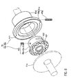
- FIG. 8 is an exploded perspective view of the induction detecting rotary encoder 4a.
- the induction detecting rotary encoder 4a has a first rotary encoder 40a and a second rotary encoder 50a, and is housed in a housing space 22 of the main body 2.
- the first rotary encoder 40a has a stator 41 a and a first rotor 42a.
- the first rotor 42a is provided with a key 47a engaged with the key groove 34a, and is rotatably provided around the spindle 3a.
- the stator 41a is fixed to a front side internal wall 28 of the housing space 22, when the spindle 3a is inserted.
- the first rotor 42a is provided immediately external to the spindle 3a.
- the first rotor 42a is provided at a predetermined distance from the stator 41 a and provided axially opposite to the stator 41 a.
- the first rotor 42a has a first rotor plate 48a, a first rotating cylinder 43a, and a first key 47a.
- the first rotor plate 48a is rotated in a pair with the stator 41 a in a state opposite to the stator 41 a.
- the first rotating cylinder 43a supports rotation of the first rotor plate 48a around the spindle 3a.
- the first key 47a is engaged with the first key groove 34a.
- the first rotor plate 48a is a small circular plate having a hole through which the spindle 3a is inserted.
- the first rotating cylinder 43a has a cylindrical shape externally fitted to the spindle 3a.
- the first rotating cylinder 43a is connected to a rear surface of the first rotor plate 48a so as to support the rotation of the first rotor plate 48a.
- the first rotating cylinder 43a is provided with two holes 43aa and 43ab therethrough orthogonal to the shaft.
- the first hole 43aa is engaged with the first key 47a.
- the second hole 43ab has an elongated shape having a length in a circumferential direction of the first rotating cylinder 43a.
- the second rotary encoder 50a has the stator 41a and a second rotor 51 a.
- the second rotor 51 a is provided with a key 47b engaged with the key groove 34b, and is rotatably provided around the spindle 3a.
- the second rotor 51 a is provided external to the first rotor 42a so as to surround the first rotor 42a.
- the second rotor 51a is provided at a predetermined distance from the stator 41 a and provided axially opposite to the stator 41 a.
- the second rotor 51 a Similar to the first rotor 42a, the second rotor 51 a has a second rotor plate 55a, a second rotating cylinder 52a, and a second key 47b.
- the second rotor plate 55a is rotated in a pair with the stator 41 a in a state opposite to the stator 41 a.
- the second rotating cylinder 52a supports rotation of the second rotor plate 55a around the spindle 3a.
- the second key 47b is engaged with the second key groove 34b.
- the second rotor plate 55a is an annular plate having an inner hole through which the first rotor plate 48a is loosely fitted.
- the second rotating cylinder 52a is connected to a rear surface of the second rotor plate 55a.
- the second rotating cylinder 52a has a cylindrical shape having a hole thereinside through which the first rotating cylinder 43a is loosely fitted.
- the second rotating cylinder 52a is provided with a hole 52aa therethrough orthogonal to the shaft.
- the first hole 52aa is engaged with the second key 47b.
- the second key 47b is engaged with the second key groove 34b by passing through the second hole 43ab, which is an elongated hole of the first rotating cylinder 43a.
- the second rotating cylinder 52a has a shaft receiver 52ab that supports the shaft of the spindle 3a, the shaft receiver 52ab being provided on an opposite side to the stator 41a having the first rotor 42a in between. Further, the second key 47b is provided at a substantially same position in the spindle shaft direction as the first key 47a of the first rotating cylinder 43a.
- a spindle shaft receiver 27a is provided extending toward a rear end side slightly more than the stator 41a.
- a spindle shaft receiver 43ac of the first rotating cylinder 43a is provided extending slightly more toward the stator 41a than the first rotor plate 48a.
- the spindle shaft receiver 43ac of the first rotating cylinder 43a is provided in contact with the spindle shaft receiver 27a of the main body 2. Thereby, a gap between the stator 41a and the first rotor plate 48a is appropriately secured.
- a coil spring (biasing portion; not shown in the drawing) is provided between the second rotating cylinder 52a and a partitioning plate 23.
- the second rotor 51a is biased toward the stator 41 a, and the first rotor 42a is pressed at an internal wall of the second rotating cylinder 52a.
- the first rotor 42a is also biased toward the stator 41 a.
- the spindle shaft receiver 43ac of the first rotating cylinder 43a supports the shaft of the spindle 3a, and thus the first rotating cylinder 43a is rotated with reference to the spindle 3a.
- a shaft receiver 622 of the second rotating cylinder 52a supports the shaft of the spindle 3a, and thus the second rotating cylinder 52a is also rotated with reference to the spindle 3a.
- the first key groove 34a and the second key groove 34b have different lead angles from each other.
- the first rotating cylinder 43a and the second rotating cylinder 52a are rotated at different rotation amounts (rotation phases) from each other when the spindle 3a is rotated one time.
- the first and second rotating cylinders 43a and 52a are rotated in accordance with the rotation of the spindle 3a, the first rotor plate 48a is rotated along with the first rotating cylinder 43a, and the second rotor plate 55a is rotated along with the second rotating cylinder 52a.
- the first rotor 42a is rotated at a different rotation speed from the second rotor 51 a in the second embodiment, similar to the first embodiment.
- first and second flux coupling windings 421 and 422 are also provided on the first rotor 42a opposite to the stator 41 in the second embodiment.
- a third flux coupling winding 423 is provided on the second rotor 51a opposite to the stator 41.
- First to third transmitting windings 411 to 413 and first to third receiving windings 414 to 416 are provided on the stator 41a opposite to the first and second rotors 42a and 51 a.
- the micrometer head 1 a of the second embodiment is configured substantially similar to the first embodiment, the micrometer head 1a has similar effects to those of the first embodiment.
- the embodiments of the induction detecting rotary encoder according to the present invention were explained above.
- the present invention is not limited to the embodiments above, and may be modified, added, and replaced in a variety of ways within the scope of the purpose of the present invention.
- the first to third flux coupling bodies are not necessarily embodied as the first to third flux coupling windings 421, 422, and 511, but may be provided as an electrode, a hole provided in a conductive plate, a recess, and the like.
Landscapes
- Physics & Mathematics (AREA)
- General Physics & Mathematics (AREA)
- Transmission And Conversion Of Sensor Element Output (AREA)
- Measurement Of Length, Angles, Or The Like Using Electric Or Magnetic Means (AREA)
Claims (15)
- Encodeur rotatif de détection par induction (4, 4a) comprenant :un stator (41, 41a) ;un premier rotor (42, 42a) engagé avec un axe rotatif, tournant conjointement avec l'axe rotatif et pourvu de manière à être opposé axialement au stator (41, 41a) ;un deuxième rotor (51, 51a) pourvu sur un côté périphérique externe du premier rotor (42), rotatif par rapport au premier rotor (42, 42a) et opposé axialement au stator (41, 41a) ;un dispositif de transfert de rotation adapté pour transférer la rotation de l'axe rotatif et pour faire tourner le deuxième rotor (51, 51a) à une vitesse différente de celle du premier rotor (42, 42a) ;un premier enroulement de transmission (411), un deuxième enroulement de transmission (412) et un troisième enroulement de transmission (413) pourvus dans cet ordre depuis l'intérieur de manière concentrique sur l'axe de rotation, sur une surface du stator (41, 41a) à l'opposé du premier rotor (42, 42a) et du deuxième rotor (51, 51a) ;un premier enroulement de réception (414), un deuxième enroulement de réception (415) et un troisième enroulement de réception (416) pourvus dans cet ordre depuis l'intérieur de manière concentrique sur l'axe de rotation, sur la surface du stator (41, 41a), à l'opposé du premier rotor et du deuxième rotor, et associés au premier enroulement de transmission (411), au deuxième enroulement de transmission (412) et au troisième enroulement de transmission (413) ;un premier corps d'accouplement de flux (421) et un deuxième corps d'accouplement de flux (422) pourvus dans cet ordre depuis l'intérieur de manière concentrique sur l'axe de rotation, sur la surface du premier rotor (42, 42a) à l'opposée du stator (41, 41a), le premier corps d'accouplement de flux (421) effectuant un accouplement de flux avec le premier enroulement de transmission (411) et le premier enroulement de réception (414), le deuxième corps d'accouplement de flux (422) effectuant un accouplement de flux avec le deuxième enroulement de transmission (412) et le deuxième enroulement de réception (415) ; etun troisième corps d'accouplement de flux (511) pourvu à l'extérieur du premier corps d'accouplement de flux (421) et du deuxième corps d'accouplement de flux (422), de manière concentrique à l'axe de rotation, sur la surface du deuxième rotor (51, 51a) à l'opposé du stator (41, 41a), et effectuant un accouplement de flux avec le troisième enroulement de transmission (413) et le troisième enroulement de réception (416) ;dans lequelle premier enroulement de transmission (411), le premier enroulement de réception (414) et le premier corps d'accouplement de flux (421) constituent une première piste de détection d'angle qui génère un changement cyclique N1 fois par rotation unique du premier rotor (42, 42a) ;le deuxième enroulement de transmission (412), le deuxième enroulement de réception (415) et le deuxième corps d'accouplement de flux (422) constituent une deuxième piste de détection d'angle qui génère un changement cyclique N2 fois par rotation unique du premier rotor (42, 42a) ;le troisième enroulement de transmission (413), le troisième enroulement de réception (416) et le troisième corps d'accouplement de flux (511) constituent une troisième piste de détection d'angle qui génère un changement cyclique N3 fois par rotation unique du deuxième rotor (51, 51a) ;N1, N2 et N3 sont différents les uns des autres ; etN3 est inférieur à N1 et à N2.
- Encodeur rotatif de détection par induction (4, 4a) selon la revendication 1, dans lequel N3 est égal à 2.
- Encodeur rotatif de détection par induction (4, 4a) selon la revendication 1 ou 2, dans lequel la différence entre N1 et N2 est égale à 1.
- Encodeur rotatif de détection par induction (4) selon l'une quelconque des revendications 1 à 3, dans lequel le dispositif de transfert de rotation comprend :un premier engrenage (48) pourvu sur une périphérie externe d'un premier cylindre rotatif (43) qui supporte le premier rotor (42) ;un deuxième engrenage (55) pourvu sur une périphérie externe d'un deuxième cylindre rotatif (52) qui supporte le deuxième rotor (51) ; etun moyen d'engrenage relais (53) comprenant un premier engrenage relais (53A) qui s'engage avec le premier engrenage (48), un deuxième engrenage relais (53B) qui s'engage avec le deuxième engrenage (55), et un axe d'engrenage relais (53C) qui supporte de manière concentrique le premier engrenage relais (53A) et le deuxième engrenage relais (53B) ;dans lequel le deuxième engrenage (55) comporte une dent de plus que le premier engrenage (48) et les premier engrenage relais (53A) et deuxième engrenage relais (53B) comportent le même nombre de dents.
- Encodeur rotatif de détection par induction (4a) selon l'une quelconque des revendications 1 à 3, dans lequel :ledit axe rotatif est l'axe d'un mandrin (3, 3a) comportant un filetage de direction (33) engagé avec un autre filetage (26) ;ledit mandrin (3, 3a) comprend une première rainure à clavette (34a) et une deuxième rainure à clavette (34b), ladite première rainure à clavette (34a) et ladite deuxième rainure à clavette (34b) ayant des angles de direction différents ;ledit premier rotor (42a) comprend une première clavette (47a) engagée avec ladite première rainure à clavette (34a) ; etledit deuxième rotor (51a) comprend une deuxième clavette (47b) engagée avec ladite deuxième rainure à clavette (34b),dans lequel lesdites rainures à clavette (34a, 34b) et lesdites clavettes (47a, 47b) forment ledit dispositif de transfert de rotation.
- Encodeur rotatif de détection par induction (4, 4a) selon l'une quelconque des revendications 1 à 5, dans lequel ledit premier corps d'accouplement de flux (421) et ledit deuxième corps d'accouplement de flux (422) sont respectivement un premier enroulement d'accouplement de flux (421) et un deuxième enroulement d'accouplement de flux (422), qui sont pourvus sur le premier rotor (42, 42a) opposé au stator (41, 41a).
- Encodeur rotatif de détection par induction (4, 4a) selon la revendication 6, dans lequel le premier enroulement d'accouplement de flux (421) présente une forme d'engrenage à N1 protubérances et N1 cavités, et dans lequel le deuxième enroulement d'accouplement de flux (422) présente une forme d'engrenage à N2 protubérances et N2 cavités.
- Encodeur rotatif de détection par induction selon l'une quelconque des revendications 1 à 7, dans lequel ledit troisième corps d'accouplement de flux (511) est un troisième enroulement d'accouplement de flux (511) pourvu sur le deuxième rotor (51, 51a) opposé au stator (41, 41a).
- Encodeur rotatif de détection par induction (4, 4a) selon la revendication 8, dans lequel le troisième enroulement d'accouplement de flux (511) présente une forme d'engrenage à N3 protubérances et N3 cavités.
- Tête de micromètre (1, 1a) comprenant :un corps principal (2, 2a) ;un mandrin (3, 3a) qui s'étend à partir du corps principal (2, 2a), dans lequel le mandrin comprend un filetage de direction (33) engagé avec un filetage (26) du corps principal (2, 2a) ;un encodeur rotatif de détection par induction (4, 4a) selon l'une quelconque des revendications 1 à 9, dans lequel ledit axe rotatif est un axe dudit mandrin (3, 3a) et ledit stator (41, 41a) est connecté audit corps principal (2, 2a) ;un moyen à contrôleur de transmission/réception (6) adapté pour contrôler la transmission vers l'encodeur rotatif de détection par induction (4, 4a) et la réception depuis celui-ci ;un processeur de calcul (7) adapté pour exécuter un processus de calcul sur base d'un signal du moyen à contrôleur de transmission/réception (6) ; etun affichage (8) adapté pour afficher un résultat de calcul fourni par le processeur de calcul (7).
- Tête de micromètre (1, 1a) selon la revendication 10, dans laquelle le moyen à contrôleur de transmission/réception (6) comprend :un premier contrôleur de transmission/réception (61) adapté pour transmettre un premier signal AC prédéterminé au premier enroulement de transmission (411) et au deuxième enroulement de transmission (412) et pour recevoir du premier enroulement de réception (411) et du deuxième enroulement de réception (415) un signal de phase pour le premier rotor (42, 42a) ;un deuxième contrôleur de transmission/réception (62) adapté pour transmettre un deuxième signal AC prédéterminé vers le troisième enroulement de transmission (413) et pour recevoir du troisième enroulement de réception (416) un signal de phase pour le deuxième rotor (51, 51a).
- Tête de micromètre (1, 1a) selon la revendication 11, dans laquelle le processeur de calcul (7) comprend :un premier calculateur d'angle de rotation (74) adapté pour calculer un angle de rotation du premier rotor (42, 42a) sur base du signal de phase pour le premier rotor en provenance du premier contrôleur de transmission/réception (61) ;un deuxième calculateur d'angle de rotation (75) adapté pour calculer un angle de rotation du deuxième rotor (51, 51a) sur base du signal de phase provenant du deuxième contrôleur de transmission/réception (62) ;un calculateur de phase de rotation (72) comprenant un calculateur de différence (76) adapté pour calculer une différence entre les angles de rotation des premier et deuxième rotors (42, 42a, 51, 51a) et un calculateur de phase de rotation totale (77) adapté pour calculer une phase de rotation totale du mandrin (3, 3a) sur base de la différence ; etun calculateur de position de mandrin (73) adapté pour calculer une quantité de déplacement totale du mandrin (3, 3a) en multipliant la phase de rotation totale du mandrin (3, 3a) par un pas dudit filetage de direction (33).
- Tête de micromètre (1, 1a) selon l'une quelconque des revendications 10 à 12, dans laquelle le dispositif de transfert de rotation est adapté pour fournir des vitesses de rotation du premier rotor (42) et du deuxième rotor (51, 51a), de telle sorte qu'une différence entre les angles de rotation du premier rotor (42, 42a) et du deuxième rotor (51, 51a) change de 360 degrés lorsque le mandrin (3, 3a) est tourné dans une plage totale de mouvement d'extension et de rétraction.
- Tête de micromètre (1) selon la revendication 13, dans laquelle le dispositif de transfert de rotation comprend les caractéristiques définies dans la revendication 4, dans laquelle le filetage de direction (33) est formé pour un nombre prédéterminé de rotations du mandrin (3, 3a) dans la plage totale de mouvement d'extension et de rétraction, et dans laquelle le nombre de dents du premier engrenage (48) est égal audit nombre prédéterminé de rotations.
- Procédé d'utilisation d'un encodeur rotatif de détection par induction (4, 4a) selon l'une quelconque des revendications 1 à 9, comprenant :la détection d'un premier signal de phase représentant un angle de rotation du premier rotor (42, 42a) ;le calcul d'un angle de rotation du premier rotor (42, 42a) sur base du premier signal de phase ;la détection d'un deuxième signal de phase représentant un angle de rotation du deuxième rotor (51, 51a) ;le calcul d'un angle de rotation du deuxième rotor (51, 51a) sur base du deuxième signal de phase ;le calcul d'une différence entre les angles de rotation du premier rotor (42, 42a) et du deuxième rotor (51, 51a) ; etle calcul d'une phase de rotation totale de l'axe rotatif sur base de la différence entre les angles de rotation du premier rotor (42, 42a) et du deuxième rotor (51, 51a).
Applications Claiming Priority (1)
| Application Number | Priority Date | Filing Date | Title |
|---|---|---|---|
| JP2008276420A JP5133199B2 (ja) | 2008-10-28 | 2008-10-28 | 誘導検出型ロータリーエンコーダ |
Publications (3)
| Publication Number | Publication Date |
|---|---|
| EP2182329A2 EP2182329A2 (fr) | 2010-05-05 |
| EP2182329A3 EP2182329A3 (fr) | 2013-11-13 |
| EP2182329B1 true EP2182329B1 (fr) | 2014-10-15 |
Family
ID=41490488
Family Applications (1)
| Application Number | Title | Priority Date | Filing Date |
|---|---|---|---|
| EP09174358.3A Active EP2182329B1 (fr) | 2008-10-28 | 2009-10-28 | Encodeur rotatif de détection par induction |
Country Status (4)
| Country | Link |
|---|---|
| US (1) | US8159215B2 (fr) |
| EP (1) | EP2182329B1 (fr) |
| JP (1) | JP5133199B2 (fr) |
| CN (1) | CN101726321B (fr) |
Families Citing this family (19)
| Publication number | Priority date | Publication date | Assignee | Title |
|---|---|---|---|---|
| WO2007145296A1 (fr) * | 2006-06-14 | 2007-12-21 | The Furukawa Electric Co., Ltd. | Détecteur d'angle de rotation |
| US8207729B2 (en) | 2009-02-17 | 2012-06-26 | Goodrich Corporation | Non-contact sensor system and method for displacement determination |
| JP5540308B2 (ja) * | 2009-10-16 | 2014-07-02 | 株式会社ミツトヨ | ロータリーエンコーダ |
| JP5948620B2 (ja) * | 2011-09-16 | 2016-07-06 | 株式会社ミツトヨ | 誘導検出型ロータリエンコーダ |
| US9163926B2 (en) * | 2012-01-25 | 2015-10-20 | Mitutoyo Corporation | Inductive detection type rotary encoder |
| DE102012223942A1 (de) * | 2012-12-20 | 2014-06-26 | Schaeffler Technologies Gmbh & Co. Kg | Sensoranordnung mit einem Winkelsensor sowie Wälzlageranordnung |
| JP6239824B2 (ja) * | 2013-01-18 | 2017-11-29 | 株式会社ミツトヨ | 誘導検出型ロータリエンコーダ |
| DE102013218768A1 (de) * | 2013-09-19 | 2015-03-19 | Dr. Johannes Heidenhain Gmbh | Induktive Positionsmesseinrichtung |
| JP6277047B2 (ja) * | 2014-04-09 | 2018-02-07 | 株式会社ミツトヨ | 誘導検出型ロータリエンコーダ |
| WO2016140149A1 (fr) * | 2015-03-05 | 2016-09-09 | 日立オートモティブシステムズ株式会社 | Dispositif de détection de position |
| GB201513881D0 (en) * | 2015-08-06 | 2015-09-23 | Skf Ab | Absolute angle determination |
| US9914477B2 (en) * | 2015-12-10 | 2018-03-13 | Ksr Ip Holdings Llc | Inductive steering torque and angle sensor |
| CN110494716B (zh) * | 2017-04-13 | 2022-04-15 | 索尼公司 | 位置检测装置和位置检测方法 |
| US11353338B2 (en) * | 2017-08-21 | 2022-06-07 | KSR IP Holdings, LLC | Inductive sensor module assembly with a center signal processor |
| JP7096009B2 (ja) | 2018-02-21 | 2022-07-05 | 株式会社ミツトヨ | 位置検出エンコーダ及び位置検出エンコーダの製造方法 |
| EP4012351B1 (fr) | 2020-12-08 | 2023-02-08 | Dr. Johannes Heidenhain GmbH | Élément de dètection et dispositif de mesure de position inductif pourvu dudit élément de détection |
| ES2994907T3 (en) * | 2021-10-25 | 2025-02-03 | Heidenhain Gmbh Dr Johannes | Inductive angle measuring device |
| JP2023130069A (ja) * | 2022-03-07 | 2023-09-20 | 株式会社豊田中央研究所 | センサ一体型の転がり軸受 |
| CN114858192B (zh) * | 2022-03-17 | 2023-04-07 | 哈尔滨理工大学 | 一种基于双轮结构双霍尔磁电编码器及其角度解算方法 |
Family Cites Families (16)
| Publication number | Priority date | Publication date | Assignee | Title |
|---|---|---|---|---|
| US5796248A (en) * | 1994-09-19 | 1998-08-18 | Ford Motor Company | Method and apparatus for commutating a three-phase variable reluctance motor |
| JP4001989B2 (ja) | 1996-11-29 | 2007-10-31 | ドクトル・ヨハネス・ハイデンハイン・ゲゼルシヤフト・ミツト・ベシユレンクテル・ハフツング | 位置測定装置の走査部材 |
| DE60007202T2 (de) * | 1999-03-15 | 2004-11-04 | Goto, Atsutoshi, Fuchu | Induktiver Stellungsdetektor |
| FR2808872B1 (fr) * | 2000-05-15 | 2002-08-16 | Cit Alcatel | Capteurs inductifs en etoile pour la detection de la position radiale d'un rotor dans un stator |
| JP4088073B2 (ja) * | 2002-01-11 | 2008-05-21 | 株式会社ミツトヨ | 絶対位置測定装置 |
| JP3588455B2 (ja) * | 2002-01-23 | 2004-11-10 | 三菱電機株式会社 | 回転角度検出器の製造方法 |
| JP4199826B2 (ja) * | 2003-02-19 | 2008-12-24 | ミネベア株式会社 | 鉄心巻線を用いたバリアブルリラクタンス型角度検出器およびその鉄心巻線の製造方法 |
| DE10320990A1 (de) * | 2003-05-09 | 2004-11-25 | Dr. Johannes Heidenhain Gmbh | Induktiver Drehwinkelsensor und damit ausgestatteter Drehgeber |
| JP4188160B2 (ja) * | 2003-07-25 | 2008-11-26 | ミネベア株式会社 | 回転角センサー |
| JP2005134247A (ja) * | 2003-10-30 | 2005-05-26 | Mitsutoyo Corp | 誘導型変位検出装置及びマイクロメータ |
| JP4533165B2 (ja) * | 2005-01-28 | 2010-09-01 | 株式会社ミツトヨ | 絶対位置測定装置 |
| JP4869769B2 (ja) * | 2005-04-19 | 2012-02-08 | 株式会社ミツトヨ | アブソリュートロータリエンコーダ及びマイクロメータ |
| CN100420914C (zh) | 2005-04-19 | 2008-09-24 | 三丰株式会社 | 绝对式旋转编码器和千分尺 |
| DE102006046531A1 (de) * | 2006-09-29 | 2008-04-03 | Dr. Johannes Heidenhain Gmbh | Drehgeber und Verfahren zu dessen Betrieb |
| CN101226064A (zh) * | 2007-12-14 | 2008-07-23 | 南京航空航天大学 | 电感式转子位置传感器 |
| JP5540308B2 (ja) * | 2009-10-16 | 2014-07-02 | 株式会社ミツトヨ | ロータリーエンコーダ |
-
2008
- 2008-10-28 JP JP2008276420A patent/JP5133199B2/ja active Active
-
2009
- 2009-10-13 US US12/577,883 patent/US8159215B2/en active Active
- 2009-10-28 CN CN200910208505.6A patent/CN101726321B/zh active Active
- 2009-10-28 EP EP09174358.3A patent/EP2182329B1/fr active Active
Also Published As
| Publication number | Publication date |
|---|---|
| US20100102803A1 (en) | 2010-04-29 |
| CN101726321B (zh) | 2012-12-26 |
| EP2182329A3 (fr) | 2013-11-13 |
| EP2182329A2 (fr) | 2010-05-05 |
| CN101726321A (zh) | 2010-06-09 |
| JP2010107209A (ja) | 2010-05-13 |
| US8159215B2 (en) | 2012-04-17 |
| JP5133199B2 (ja) | 2013-01-30 |
Similar Documents
| Publication | Publication Date | Title |
|---|---|---|
| EP2182329A2 (fr) | Encodeur rotatif de détection par induction | |
| EP2312272B1 (fr) | Encodeur rotatif | |
| US7584551B2 (en) | Absolute position measuring apparatus | |
| US9243884B2 (en) | Inductive detection type rotary encoder | |
| JP6204813B2 (ja) | インダクティブ位置測定装置 | |
| JP5022724B2 (ja) | 絶対位置測定装置 | |
| EP2620739B1 (fr) | Codeur rotatif de type détection inductive | |
| CN104487807A (zh) | 用于活动件的冗余绝对位置确定的设备和方法 | |
| US6772087B2 (en) | Absolute position measuring device | |
| US12434761B2 (en) | Stroke sensor | |
| KR20150004740A (ko) | 눈금자를 스캐닝하는 스캐닝 유닛 및 위치 측정 장치 | |
| JP4533165B2 (ja) | 絶対位置測定装置 | |
| JP6133589B2 (ja) | 誘導検出型ロータリエンコーダ | |
| JP4866653B2 (ja) | 絶対位置測定装置 | |
| JP2006090982A (ja) | 回転角度検出装置 | |
| JP2007155482A (ja) | 回転角度検出装置 | |
| CN120270335A (zh) | 用于汽车的线控转向系统和汽车 | |
| JP2006300621A (ja) | 多回転絶対角度検出機構および検出方法 | |
| KR20120034946A (ko) | 회전형 토크 측정장치에 구비되는 알피엠 측정장치 |
Legal Events
| Date | Code | Title | Description |
|---|---|---|---|
| PUAI | Public reference made under article 153(3) epc to a published international application that has entered the european phase |
Free format text: ORIGINAL CODE: 0009012 |
|
| AK | Designated contracting states |
Kind code of ref document: A2 Designated state(s): AT BE BG CH CY CZ DE DK EE ES FI FR GB GR HR HU IE IS IT LI LT LU LV MC MK MT NL NO PL PT RO SE SI SK SM TR |
|
| AX | Request for extension of the european patent |
Extension state: AL BA RS |
|
| PUAL | Search report despatched |
Free format text: ORIGINAL CODE: 0009013 |
|
| AK | Designated contracting states |
Kind code of ref document: A3 Designated state(s): AT BE BG CH CY CZ DE DK EE ES FI FR GB GR HR HU IE IS IT LI LT LU LV MC MK MT NL NO PL PT RO SE SI SK SM TR |
|
| AX | Request for extension of the european patent |
Extension state: AL BA RS |
|
| RIC1 | Information provided on ipc code assigned before grant |
Ipc: G01D 5/20 20060101AFI20131008BHEP |
|
| 17P | Request for examination filed |
Effective date: 20140317 |
|
| RBV | Designated contracting states (corrected) |
Designated state(s): AT BE BG CH CY CZ DE DK EE ES FI FR GB GR HR HU IE IS IT LI LT LU LV MC MK MT NL NO PL PT RO SE SI SK SM TR |
|
| GRAP | Despatch of communication of intention to grant a patent |
Free format text: ORIGINAL CODE: EPIDOSNIGR1 |
|
| INTG | Intention to grant announced |
Effective date: 20140522 |
|
| GRAS | Grant fee paid |
Free format text: ORIGINAL CODE: EPIDOSNIGR3 |
|
| GRAA | (expected) grant |
Free format text: ORIGINAL CODE: 0009210 |
|
| AK | Designated contracting states |
Kind code of ref document: B1 Designated state(s): AT BE BG CH CY CZ DE DK EE ES FI FR GB GR HR HU IE IS IT LI LT LU LV MC MK MT NL NO PL PT RO SE SI SK SM TR |
|
| REG | Reference to a national code |
Ref country code: GB Ref legal event code: FG4D Ref country code: CH Ref legal event code: EP |
|
| REG | Reference to a national code |
Ref country code: IE Ref legal event code: FG4D |
|
| REG | Reference to a national code |
Ref country code: AT Ref legal event code: REF Ref document number: 691890 Country of ref document: AT Kind code of ref document: T Effective date: 20141115 |
|
| REG | Reference to a national code |
Ref country code: DE Ref legal event code: R096 Ref document number: 602009027170 Country of ref document: DE Effective date: 20141127 |
|
| REG | Reference to a national code |
Ref country code: NL Ref legal event code: VDEP Effective date: 20141015 |
|
| REG | Reference to a national code |
Ref country code: AT Ref legal event code: MK05 Ref document number: 691890 Country of ref document: AT Kind code of ref document: T Effective date: 20141015 |
|
| REG | Reference to a national code |
Ref country code: LT Ref legal event code: MG4D |
|
| PG25 | Lapsed in a contracting state [announced via postgrant information from national office to epo] |
Ref country code: NL Free format text: LAPSE BECAUSE OF FAILURE TO SUBMIT A TRANSLATION OF THE DESCRIPTION OR TO PAY THE FEE WITHIN THE PRESCRIBED TIME-LIMIT Effective date: 20141015 |
|
| PG25 | Lapsed in a contracting state [announced via postgrant information from national office to epo] |
Ref country code: IS Free format text: LAPSE BECAUSE OF FAILURE TO SUBMIT A TRANSLATION OF THE DESCRIPTION OR TO PAY THE FEE WITHIN THE PRESCRIBED TIME-LIMIT Effective date: 20150215 Ref country code: ES Free format text: LAPSE BECAUSE OF FAILURE TO SUBMIT A TRANSLATION OF THE DESCRIPTION OR TO PAY THE FEE WITHIN THE PRESCRIBED TIME-LIMIT Effective date: 20141015 Ref country code: PT Free format text: LAPSE BECAUSE OF FAILURE TO SUBMIT A TRANSLATION OF THE DESCRIPTION OR TO PAY THE FEE WITHIN THE PRESCRIBED TIME-LIMIT Effective date: 20150216 Ref country code: LT Free format text: LAPSE BECAUSE OF FAILURE TO SUBMIT A TRANSLATION OF THE DESCRIPTION OR TO PAY THE FEE WITHIN THE PRESCRIBED TIME-LIMIT Effective date: 20141015 Ref country code: NO Free format text: LAPSE BECAUSE OF FAILURE TO SUBMIT A TRANSLATION OF THE DESCRIPTION OR TO PAY THE FEE WITHIN THE PRESCRIBED TIME-LIMIT Effective date: 20150115 Ref country code: FI Free format text: LAPSE BECAUSE OF FAILURE TO SUBMIT A TRANSLATION OF THE DESCRIPTION OR TO PAY THE FEE WITHIN THE PRESCRIBED TIME-LIMIT Effective date: 20141015 |
|
| PG25 | Lapsed in a contracting state [announced via postgrant information from national office to epo] |
Ref country code: LV Free format text: LAPSE BECAUSE OF FAILURE TO SUBMIT A TRANSLATION OF THE DESCRIPTION OR TO PAY THE FEE WITHIN THE PRESCRIBED TIME-LIMIT Effective date: 20141015 Ref country code: GR Free format text: LAPSE BECAUSE OF FAILURE TO SUBMIT A TRANSLATION OF THE DESCRIPTION OR TO PAY THE FEE WITHIN THE PRESCRIBED TIME-LIMIT Effective date: 20150116 Ref country code: HR Free format text: LAPSE BECAUSE OF FAILURE TO SUBMIT A TRANSLATION OF THE DESCRIPTION OR TO PAY THE FEE WITHIN THE PRESCRIBED TIME-LIMIT Effective date: 20141015 Ref country code: AT Free format text: LAPSE BECAUSE OF FAILURE TO SUBMIT A TRANSLATION OF THE DESCRIPTION OR TO PAY THE FEE WITHIN THE PRESCRIBED TIME-LIMIT Effective date: 20141015 Ref country code: SE Free format text: LAPSE BECAUSE OF FAILURE TO SUBMIT A TRANSLATION OF THE DESCRIPTION OR TO PAY THE FEE WITHIN THE PRESCRIBED TIME-LIMIT Effective date: 20141015 Ref country code: PL Free format text: LAPSE BECAUSE OF FAILURE TO SUBMIT A TRANSLATION OF THE DESCRIPTION OR TO PAY THE FEE WITHIN THE PRESCRIBED TIME-LIMIT Effective date: 20141015 Ref country code: CY Free format text: LAPSE BECAUSE OF FAILURE TO SUBMIT A TRANSLATION OF THE DESCRIPTION OR TO PAY THE FEE WITHIN THE PRESCRIBED TIME-LIMIT Effective date: 20141015 |
|
| REG | Reference to a national code |
Ref country code: CH Ref legal event code: PL |
|
| PG25 | Lapsed in a contracting state [announced via postgrant information from national office to epo] |
Ref country code: BE Free format text: LAPSE BECAUSE OF NON-PAYMENT OF DUE FEES Effective date: 20141031 |
|
| REG | Reference to a national code |
Ref country code: DE Ref legal event code: R097 Ref document number: 602009027170 Country of ref document: DE |
|
| REG | Reference to a national code |
Ref country code: IE Ref legal event code: MM4A |
|
| PG25 | Lapsed in a contracting state [announced via postgrant information from national office to epo] |
Ref country code: CZ Free format text: LAPSE BECAUSE OF FAILURE TO SUBMIT A TRANSLATION OF THE DESCRIPTION OR TO PAY THE FEE WITHIN THE PRESCRIBED TIME-LIMIT Effective date: 20141015 Ref country code: RO Free format text: LAPSE BECAUSE OF FAILURE TO SUBMIT A TRANSLATION OF THE DESCRIPTION OR TO PAY THE FEE WITHIN THE PRESCRIBED TIME-LIMIT Effective date: 20141015 Ref country code: LI Free format text: LAPSE BECAUSE OF NON-PAYMENT OF DUE FEES Effective date: 20141031 Ref country code: DK Free format text: LAPSE BECAUSE OF FAILURE TO SUBMIT A TRANSLATION OF THE DESCRIPTION OR TO PAY THE FEE WITHIN THE PRESCRIBED TIME-LIMIT Effective date: 20141015 Ref country code: MC Free format text: LAPSE BECAUSE OF FAILURE TO SUBMIT A TRANSLATION OF THE DESCRIPTION OR TO PAY THE FEE WITHIN THE PRESCRIBED TIME-LIMIT Effective date: 20141015 Ref country code: SK Free format text: LAPSE BECAUSE OF FAILURE TO SUBMIT A TRANSLATION OF THE DESCRIPTION OR TO PAY THE FEE WITHIN THE PRESCRIBED TIME-LIMIT Effective date: 20141015 Ref country code: CH Free format text: LAPSE BECAUSE OF NON-PAYMENT OF DUE FEES Effective date: 20141031 Ref country code: EE Free format text: LAPSE BECAUSE OF FAILURE TO SUBMIT A TRANSLATION OF THE DESCRIPTION OR TO PAY THE FEE WITHIN THE PRESCRIBED TIME-LIMIT Effective date: 20141015 |
|
| PLBE | No opposition filed within time limit |
Free format text: ORIGINAL CODE: 0009261 |
|
| STAA | Information on the status of an ep patent application or granted ep patent |
Free format text: STATUS: NO OPPOSITION FILED WITHIN TIME LIMIT |
|
| PG25 | Lapsed in a contracting state [announced via postgrant information from national office to epo] |
Ref country code: IT Free format text: LAPSE BECAUSE OF FAILURE TO SUBMIT A TRANSLATION OF THE DESCRIPTION OR TO PAY THE FEE WITHIN THE PRESCRIBED TIME-LIMIT Effective date: 20141015 |
|
| 26N | No opposition filed |
Effective date: 20150716 |
|
| REG | Reference to a national code |
Ref country code: FR Ref legal event code: PLFP Year of fee payment: 7 |
|
| PG25 | Lapsed in a contracting state [announced via postgrant information from national office to epo] |
Ref country code: IE Free format text: LAPSE BECAUSE OF NON-PAYMENT OF DUE FEES Effective date: 20141028 |
|
| PG25 | Lapsed in a contracting state [announced via postgrant information from national office to epo] |
Ref country code: SI Free format text: LAPSE BECAUSE OF FAILURE TO SUBMIT A TRANSLATION OF THE DESCRIPTION OR TO PAY THE FEE WITHIN THE PRESCRIBED TIME-LIMIT Effective date: 20141015 |
|
| PG25 | Lapsed in a contracting state [announced via postgrant information from national office to epo] |
Ref country code: SM Free format text: LAPSE BECAUSE OF FAILURE TO SUBMIT A TRANSLATION OF THE DESCRIPTION OR TO PAY THE FEE WITHIN THE PRESCRIBED TIME-LIMIT Effective date: 20141015 |
|
| PG25 | Lapsed in a contracting state [announced via postgrant information from national office to epo] |
Ref country code: BG Free format text: LAPSE BECAUSE OF FAILURE TO SUBMIT A TRANSLATION OF THE DESCRIPTION OR TO PAY THE FEE WITHIN THE PRESCRIBED TIME-LIMIT Effective date: 20141015 |
|
| PG25 | Lapsed in a contracting state [announced via postgrant information from national office to epo] |
Ref country code: HU Free format text: LAPSE BECAUSE OF FAILURE TO SUBMIT A TRANSLATION OF THE DESCRIPTION OR TO PAY THE FEE WITHIN THE PRESCRIBED TIME-LIMIT; INVALID AB INITIO Effective date: 20091028 Ref country code: LU Free format text: LAPSE BECAUSE OF NON-PAYMENT OF DUE FEES Effective date: 20141028 Ref country code: TR Free format text: LAPSE BECAUSE OF FAILURE TO SUBMIT A TRANSLATION OF THE DESCRIPTION OR TO PAY THE FEE WITHIN THE PRESCRIBED TIME-LIMIT Effective date: 20141015 Ref country code: MT Free format text: LAPSE BECAUSE OF FAILURE TO SUBMIT A TRANSLATION OF THE DESCRIPTION OR TO PAY THE FEE WITHIN THE PRESCRIBED TIME-LIMIT Effective date: 20141015 |
|
| REG | Reference to a national code |
Ref country code: FR Ref legal event code: PLFP Year of fee payment: 8 |
|
| REG | Reference to a national code |
Ref country code: FR Ref legal event code: PLFP Year of fee payment: 9 |
|
| PG25 | Lapsed in a contracting state [announced via postgrant information from national office to epo] |
Ref country code: MK Free format text: LAPSE BECAUSE OF FAILURE TO SUBMIT A TRANSLATION OF THE DESCRIPTION OR TO PAY THE FEE WITHIN THE PRESCRIBED TIME-LIMIT Effective date: 20141015 |
|
| REG | Reference to a national code |
Ref country code: FR Ref legal event code: PLFP Year of fee payment: 10 |
|
| PGFP | Annual fee paid to national office [announced via postgrant information from national office to epo] |
Ref country code: DE Payment date: 20251021 Year of fee payment: 17 |
|
| PGFP | Annual fee paid to national office [announced via postgrant information from national office to epo] |
Ref country code: GB Payment date: 20251022 Year of fee payment: 17 |
|
| PGFP | Annual fee paid to national office [announced via postgrant information from national office to epo] |
Ref country code: FR Payment date: 20251029 Year of fee payment: 17 |