EP2182365B1 - Analyseur d'échantillon - Google Patents
Analyseur d'échantillon Download PDFInfo
- Publication number
- EP2182365B1 EP2182365B1 EP09013530.2A EP09013530A EP2182365B1 EP 2182365 B1 EP2182365 B1 EP 2182365B1 EP 09013530 A EP09013530 A EP 09013530A EP 2182365 B1 EP2182365 B1 EP 2182365B1
- Authority
- EP
- European Patent Office
- Prior art keywords
- sample
- detector
- measurement
- measurement sample
- light
- Prior art date
- Legal status (The legal status is an assumption and is not a legal conclusion. Google has not performed a legal analysis and makes no representation as to the accuracy of the status listed.)
- Active
Links
Images









Classifications
-
- G—PHYSICS
- G01—MEASURING; TESTING
- G01N—INVESTIGATING OR ANALYSING MATERIALS BY DETERMINING THEIR CHEMICAL OR PHYSICAL PROPERTIES
- G01N15/00—Investigating characteristics of particles; Investigating permeability, pore-volume or surface-area of porous materials
- G01N15/10—Investigating individual particles
- G01N15/1031—Investigating individual particles by measuring electrical or magnetic effects
- G01N15/12—Investigating individual particles by measuring electrical or magnetic effects by observing changes in resistance or impedance across apertures when traversed by individual particles, e.g. by using the Coulter principle
-
- G—PHYSICS
- G01—MEASURING; TESTING
- G01N—INVESTIGATING OR ANALYSING MATERIALS BY DETERMINING THEIR CHEMICAL OR PHYSICAL PROPERTIES
- G01N33/00—Investigating or analysing materials by specific methods not covered by groups G01N1/00 - G01N31/00
- G01N33/48—Biological material, e.g. blood, urine; Haemocytometers
- G01N33/50—Chemical analysis of biological material, e.g. blood, urine; Testing involving biospecific ligand binding methods; Immunological testing
- G01N33/5005—Chemical analysis of biological material, e.g. blood, urine; Testing involving biospecific ligand binding methods; Immunological testing involving human or animal cells
- G01N33/5094—Chemical analysis of biological material, e.g. blood, urine; Testing involving biospecific ligand binding methods; Immunological testing involving human or animal cells for blood cell populations
-
- G—PHYSICS
- G01—MEASURING; TESTING
- G01N—INVESTIGATING OR ANALYSING MATERIALS BY DETERMINING THEIR CHEMICAL OR PHYSICAL PROPERTIES
- G01N15/00—Investigating characteristics of particles; Investigating permeability, pore-volume or surface-area of porous materials
- G01N15/06—Investigating concentration of particle suspensions
-
- G—PHYSICS
- G01—MEASURING; TESTING
- G01N—INVESTIGATING OR ANALYSING MATERIALS BY DETERMINING THEIR CHEMICAL OR PHYSICAL PROPERTIES
- G01N15/00—Investigating characteristics of particles; Investigating permeability, pore-volume or surface-area of porous materials
- G01N15/06—Investigating concentration of particle suspensions
- G01N15/0656—Investigating concentration of particle suspensions using electric, e.g. electrostatic methods or magnetic methods
-
- G—PHYSICS
- G01—MEASURING; TESTING
- G01N—INVESTIGATING OR ANALYSING MATERIALS BY DETERMINING THEIR CHEMICAL OR PHYSICAL PROPERTIES
- G01N15/00—Investigating characteristics of particles; Investigating permeability, pore-volume or surface-area of porous materials
- G01N15/10—Investigating individual particles
- G01N15/1031—Investigating individual particles by measuring electrical or magnetic effects
-
- G—PHYSICS
- G01—MEASURING; TESTING
- G01N—INVESTIGATING OR ANALYSING MATERIALS BY DETERMINING THEIR CHEMICAL OR PHYSICAL PROPERTIES
- G01N15/00—Investigating characteristics of particles; Investigating permeability, pore-volume or surface-area of porous materials
- G01N15/10—Investigating individual particles
- G01N15/14—Optical investigation techniques, e.g. flow cytometry
-
- G—PHYSICS
- G01—MEASURING; TESTING
- G01N—INVESTIGATING OR ANALYSING MATERIALS BY DETERMINING THEIR CHEMICAL OR PHYSICAL PROPERTIES
- G01N15/00—Investigating characteristics of particles; Investigating permeability, pore-volume or surface-area of porous materials
- G01N15/10—Investigating individual particles
- G01N15/14—Optical investigation techniques, e.g. flow cytometry
- G01N15/1468—Optical investigation techniques, e.g. flow cytometry with spatial resolution of the texture or inner structure of the particle
- G01N15/147—Optical investigation techniques, e.g. flow cytometry with spatial resolution of the texture or inner structure of the particle the analysis being performed on a sample stream
-
- G—PHYSICS
- G01—MEASURING; TESTING
- G01N—INVESTIGATING OR ANALYSING MATERIALS BY DETERMINING THEIR CHEMICAL OR PHYSICAL PROPERTIES
- G01N21/00—Investigating or analysing materials by the use of optical means, i.e. using sub-millimetre waves, infrared, visible or ultraviolet light
- G01N21/17—Systems in which incident light is modified in accordance with the properties of the material investigated
-
- G—PHYSICS
- G01—MEASURING; TESTING
- G01N—INVESTIGATING OR ANALYSING MATERIALS BY DETERMINING THEIR CHEMICAL OR PHYSICAL PROPERTIES
- G01N27/00—Investigating or analysing materials by the use of electric, electrochemical, or magnetic means
-
- G—PHYSICS
- G01—MEASURING; TESTING
- G01N—INVESTIGATING OR ANALYSING MATERIALS BY DETERMINING THEIR CHEMICAL OR PHYSICAL PROPERTIES
- G01N33/00—Investigating or analysing materials by specific methods not covered by groups G01N1/00 - G01N31/00
- G01N33/48—Biological material, e.g. blood, urine; Haemocytometers
- G01N33/483—Physical analysis of biological material
- G01N33/487—Physical analysis of biological material of liquid biological material
- G01N33/49—Blood
- G01N33/4915—Blood using flow cells
-
- G—PHYSICS
- G01—MEASURING; TESTING
- G01N—INVESTIGATING OR ANALYSING MATERIALS BY DETERMINING THEIR CHEMICAL OR PHYSICAL PROPERTIES
- G01N35/00—Automatic analysis not limited to methods or materials provided for in any single one of groups G01N1/00 - G01N33/00; Handling materials therefor
- G01N35/00584—Control arrangements for automatic analysers
- G01N35/00594—Quality control, including calibration or testing of components of the analyser
- G01N35/00603—Reinspection of samples
-
- G—PHYSICS
- G01—MEASURING; TESTING
- G01N—INVESTIGATING OR ANALYSING MATERIALS BY DETERMINING THEIR CHEMICAL OR PHYSICAL PROPERTIES
- G01N15/00—Investigating characteristics of particles; Investigating permeability, pore-volume or surface-area of porous materials
- G01N15/06—Investigating concentration of particle suspensions
- G01N15/075—Investigating concentration of particle suspensions by optical means
-
- G—PHYSICS
- G01—MEASURING; TESTING
- G01N—INVESTIGATING OR ANALYSING MATERIALS BY DETERMINING THEIR CHEMICAL OR PHYSICAL PROPERTIES
- G01N15/00—Investigating characteristics of particles; Investigating permeability, pore-volume or surface-area of porous materials
- G01N15/01—Investigating characteristics of particles; Investigating permeability, pore-volume or surface-area of porous materials specially adapted for biological cells, e.g. blood cells
- G01N2015/018—Platelets
-
- G—PHYSICS
- G01—MEASURING; TESTING
- G01N—INVESTIGATING OR ANALYSING MATERIALS BY DETERMINING THEIR CHEMICAL OR PHYSICAL PROPERTIES
- G01N15/00—Investigating characteristics of particles; Investigating permeability, pore-volume or surface-area of porous materials
- G01N15/10—Investigating individual particles
- G01N2015/1019—Associating Coulter-counter and optical flow cytometer [OFC]
-
- G—PHYSICS
- G01—MEASURING; TESTING
- G01N—INVESTIGATING OR ANALYSING MATERIALS BY DETERMINING THEIR CHEMICAL OR PHYSICAL PROPERTIES
- G01N15/00—Investigating characteristics of particles; Investigating permeability, pore-volume or surface-area of porous materials
- G01N15/10—Investigating individual particles
- G01N15/1031—Investigating individual particles by measuring electrical or magnetic effects
- G01N15/12—Investigating individual particles by measuring electrical or magnetic effects by observing changes in resistance or impedance across apertures when traversed by individual particles, e.g. by using the Coulter principle
- G01N2015/135—Electrodes
Definitions
- the present invention relates to a sample analyzer for analyzing predetermined components in a sample such as blood, urine and the like.
- sample analyzers have been developed for measuring the size of predetermined component particles in a sample such as blood, urine and the like, and analyzing the state of the particle distributions. Particularly in sample analyzers for detecting the distribution states of red blood cells, white blood cells, platelets and the like, red blood cells and platelets are measured by using an electrical resistance type measuring device since platelets have a relatively small size of 1 to 4 ⁇ m compared to the size of red blood cells which are 7 to 8 ⁇ m.
- red blood cells may exits. Also, collapsed red blood cells have smaller size than usual. In those cases, red blood cells and platelets can not be reliably differentiated simply by the size.
- Japanese Laid-Open Patent Publication No. 2000-275163 discloses a particle analyzer which produces highly reliable measurement results by measuring platelets by using both an electrical resistance type measuring device and an optical measuring device.
- This particle analyzer adopts more reliable platelet number between a platelet number by the electrical resistance type measuring device and a platelet number by the optical measuring device.
- a first aspect of the present invention is a sample analyzer comprising: a sample preparing section for preparing first and second measurement sample including reagent and sample; a first detector for detecting a predetermined component in the first measurement sample prepared by the sample preparing section; a second detector for detecting the predetermined component in the second measurement sample prepared by the sample preparing section; and a controller configured for performing operations, comprising: (a) controlling the first detector to detect the predetermined component in the first measurement sample prepared by the sample preparing section; (b) determining the reliability of the result detected by the first detector; (c) controlling the sample preparing section to prepare the second measurement sample from the same sample when the result has been determined to be unreliable; and (d) controlling the second detector to detect the predetermined component in the second measurement sample.
- a second aspect of the present invention is a sample analyzer comprising: a sample preparing section for preparing first and second measurement sample including reagent and sample; a first detector for detecting a predetermined component in the first and second measurement sample prepared by the sample preparing section; and a controller configured for performing operations, comprising: (a) controlling the first detector to detect the predetermined component in the first measurement sample prepared by the sample preparing section using a first detection condition; (b) determining the reliability of the result detected by the first detector; (c) controlling the sample preparing section to prepare the second measurement sample from the same sample when the result has been determined to be unreliable; and (d) controlling the first detector to detect the predetermined component in the second measurement sample using a second detection condition which is different from the first detection condition.
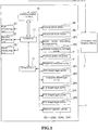
- FIG. 1 is a block diagram showing the structure of a first embodiment of the sample analyzer of the present invention.
- the sample analyzer of the first embodiment of the present invention is configured by connecting an analyzer body 1 and an operation and display device 2 so as to be capable of data communication.
- the operation and display device 2 has sample analysis software installed for various types of setting related to analysis, displaying analysis results and the like; instructions are transmitted to the analyzer body 1 and measurement data are received from the analyzer body 1 via data communication between the analyzer body 1 and the operation and display device 2.
- FIG. 2 is a perspective view showing the internal structure of the analyzer body 1 of the first embodiment of the present invention
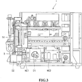
- FIG. 3 is a frontal view showing the internal structure of the analyzer body 1 of the first embodiment of the present invention.
- the analyzer body 1 is a blood analyzer for analyzing (measuring analyzing and the like) blood (sample) contained in a sealed container (initial container of a measurement sample) collection tube 3, and is provided with a sample placement section for placing the collection tube 3 at a predetermined position within the analyzer body 1, a sample preparing section for preparing a measurement sample by measuring and diluting the blood within the collection tube 3, and measuring units D1, D2, D3 for measuring the diluted blood.
- the sample preparing section is provided with an aspirating tube (aspirator) 14 for piercing a cap 3a sealing the interior of the collection tube 3 and aspirating the sample within the collection tube 3, which is disposed at a position for preparing a sample for various analyses by aspirating a predetermined amount of blood from within the collection tube 3 and mixing reagent within a first mixing chamber (first container: HGB/RBC chamber) MC1, second mixing chamber (second container: WBC chamber) MC2, third mixing chamber (third container: RET chamber) MC3, or fourth mixing chamber (fourth container: PLT chamber) MC4, a horizontal drive section for horizontally moving the aspirating tube 14, and a vertical drive section for vertically moving the aspirating tube 14.
- first mixing chamber first container: HGB/RBC chamber
- second mixing chamber second container: WBC chamber
- third mixing chamber third container: RET chamber
- fourth mixing chamber fourth mixing chamber
- the horizontal drive section is provided with a stepping motor (horizontal drive motor) 69 as a drive source
- the vertical drive section is provided with a stepping motor (vertical drive motor) 68 as a drive source.
- the aspirating tube 14 has a flow channel extending through its interior in the longitudinal direction, and has an aspiration orifice formed near the tip for aspirating a sample or air, the present invention is not particularly limited to this arrangement.
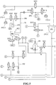
- FIGS. 4 and 5 are fluid channel diagrams of the analyzer body 1 of the first embodiment. As shown in FIGS. 4 and 5 , reagent containers accommodating a reagent are provided in the analyzer body 1 and the reagent container is connected to the fluid channel.
- the reagent containers used in the first embodiment are a dilution liquid container EPK-V for accommodating dilution liquid (cleaning liquid) EPK, hemoglobin hemolytic agent container SLS-V for accommodating hemoglobin hemolytic agent SLS, white blood cell classifying hemolytic agent container (common reagent container) FFD-V for accommodating white blood cell classifying hemolytic agent FFD for dissolving red blood cells, and white blood cell classifying stain container (special reagent container) FFS-V for accommodating white blood cell classifying stain FFS.
- EPK-V for accommodating dilution liquid (cleaning liquid) EPK
- hemoglobin hemolytic agent container SLS-V for accommodating hemoglobin hemolytic agent SLS
- white blood cell classifying hemolytic agent container common reagent container
- FFD-V for accommodating white blood cell classifying hemolytic agent FFD for dissolving red blood cells
- white blood cell classifying stain container special reagent container
- FFS-V for accommodating white blood cell classifying stain FFS.
- FIG. 6 is a fluid channel diagram provided with the RET measurement chamber MC3 of the analyzer body 1 of the first embodiment. Similar to FIGS. 4 and 5 , reagent containers accommodating a reagent can be provided in the analyzer body 1 and the reagent containers may be connected to the fluid channel.
- the fluid channel provided with the RET measurement chamber MC3 is provided with a reticulocyte stain container RES-V for containing stain RES used to stain reticulocytes, and reticulocyte diluting liquid container RED-V for containing diluting liquid RED used for reticulocyte measurement.
- FIG. 7 is a fluid channel diagram provided with the PLT measurement chamber MC4 of the analyzer body 1 of the first embodiment. Similar to FIGS. 4 and 5 , reagent containers accommodating a reagent can be provided in the analyzer body 1 and the reagent containers may be connected to the fluid channel.
- the fluid channel provided with the PLT measurement chamber MC4 is provided with a platelet stain container PLS-V for containing stain PLS used to stain platelets, and platelet diluting liquid container PLD-V for containing diluting liquid PLD used for platelet measurement.
- the platelet stain container PLS-V contains, for example Nile Blue as a stain.
- the aspirating tube 14, whole blood aspirating syringe pump SP1, and sample supplying syringe pump SP2 are provided as a sample supplier for supplying a sample from the collection tube 3 to the first mixing chamber MC1 and/or second mixing chamber MC2.
- the aspirating tube 14 moves to the first mixing chamber MC1 and second mixing chamber MC2 when a predetermined amount of whole blood has been aspirated from the collection tube 3 by the whole blood aspirating syringe pump SP1 and sample supplying syringe pump SP2. Then, the predetermined amount of whole blood sample is distributed to the first mixing chamber MC1 and second mixing chamber MC2, respectively, by the whole blood aspirating syringe pump SP1 and sample supplying syringe pump SP2. Note that during RET measurement, the whole blood sample is also supplied to the third mixing chamber MC3.
- Part of the whole blood sample is supplied to the fourth mixing chamber MC4 and temporarily stored.
- instructions are first issued to again prepare a sample and the diluting liquid PLD and stain PLS are supplied to the fourth mixing chamber MC4.
- the dilution liquid container EPK-V and the hemoglobin hemolytic agent container SLS-V are connected so as to be capable of supplying reagent to the first mixing chamber MC1. That is, an EPK diaphragm pump DP1 configures the diluting liquid reagent supplying section whereby the diluting liquid can be supplied from the diluting liquid container EPK-V to the first mixing chamber MC1 by the diluting liquid supplying (EPK) diaphragm pump DP1.
- An SLS diaphragm pump DP3 configures the hemolytic reagent supplying section whereby the hemoglobin hemolytic agent can be supplied from the hemoglobin hemolytic agent container SLS-V to the first mixing chamber MC1 by the hemolytic agent supplying (SLS) diaphragm pump DP3.
- SLS hemolytic agent supplying
- the hemolytic agent container FFD-V and stain container FFS-V are connected so as to supply reagent to the second mixing chamber MC2. That is, the hemolytic agent can be supplied from the hemolytic agent container FFD-V to the second mixing chamber MC2 via a hemolytic agent supplying (FFD) diaphragm pump DP4; the hemolytic agent supplying (FFD) diaphragm pump DP4 configures a hemolytic agent reagent supplying section.
- FFD hemolytic agent supplying
- the stain can be supplied from the stain container FFS-V to the second mixing chamber MC2 via the stain (FFS) diaphragm pump DP5; the FFS stain diaphragm pump DP5 configures a stain reagent supplying section (special reagent supplying section).
- FFS stain diaphragm pump DP5
- the reagent supplying channel from the dilution liquid container EPK-V to the first mixing chamber MC1 and the reagent supplying channel from the hemolytic agent container SLS-V to the first mixing chamber MC1 are joined at a midway confluence point CR1, forming a common reagent supplying channel T1 for both reagents which is connected to the first mixing chamber MC1.
- two types of reagent are supplied to the first mixing chamber MC1, there may be only a single reagent supplying orifice to the first mixing chamber MC1, thus simplifying the structure.
- the reagent supplying channel from the hemolytic agent container FFD-V to the second mixing chamber MC2 and the reagent supplying channel from the stain container FFS-V to the second mixing chamber MC2 are joined at a midway confluence point CR2, forming a common reagent supplying channel T2 for both reagents which is connected to the second mixing chamber MC2.
- two types of reagent are supplied to the second mixing chamber MC2, there may be only a single reagent supplying orifice to the second mixing chamber MC2, thus simplifying the structure.
- the reagent supplying channels T1 and T2 may also be provided for each reagent. That is, two reagent supplying orifices may also be provided for each chamber MC1 and MC2.
- the first measuring unit (detector, first detector) D1 performs measurements relating to red blood cells and platelets
- the second measuring unit D2 performs measurements relating to hemoglobin.
- the third measuring unit (other detector, second detector) D3 performs measurements relating to white blood cells.
- the first mixing chamber MC1 is a part for preparing a sample for analyses relating to red blood cells, platelets, and hemoglobin; the measurement sample prepared by the first mixing chamber MC1 is used in measurements performed by the first measuring unit D1 and second measuring unit D2.
- the second mixing chamber MC2 is a part for preparing a sample for analyses relating to white blood cells; the measurement sample prepared by the second mixing chamber MC2 is used in measurements performed by the third measuring unit D3.
- the first measuring unit D1 is configured as an RBC/PLT detector for performing RBC measurements (measuring red blood cell count), and PLT measurements (measuring platelet count).
- the first measuring unit D1 can perform RBC and PLT measurements via a sheath flow DC detection method, and is a so-called electrical resistance measuring device.
- the second measuring unit D2 is configured as an HGB detector for performing HGB measurements (measuring the amount of pigment in the blood).
- the second measuring unit D2 can perform HGB measurements via an SLShemoglobin method.
- the third measuring unit D3 is configured as an optical detector capable of performing WBC measurements (white blood cell count), RET measurements (reticulocyte count), and PLT measurements (platelet count).
- the third measuring unit D3 performs WBC measurements, RET measurements, and PLT measurements by flow cytometry using a semiconductor laser, and is a so-called optical type measuring device.
- the analyzer body 1 is provided with a controller 11 for controlling the operations of the sample preparing section, first measuring unit D1, second measuring unit D2, and third measuring unit D3.
- the analyzer body 1 is also provided with a drive circuit 12 for driving the electromagnetic valves SV1 through SV33, SV40, and SV41 disposed in the fluid channels configuring the sample preparing section, various types of pump motors 68, 69, SP1, SP2, P, V, DP1 through DP5 and the like; the controller 11 drives the electromagnetic valves and the like via the drive circuit 12.
- the controller (detector controller) 11 is capable of data communication with the operation and display device 2, so as to send and receive various types of signals and data to/from the operation and display device 2 through a communication interface 13.
- FIG. 8 is a block diagram showing the structure of a first embodiment of the operation and display device of the present invention.
- the operation and display device 2 is configured by a CPU (central processing unit) 21, RAM 22, memory device 23, input device 24, display device 25, output device 26, communication interface 27, portable disk drive 28, and an internal bus 29 connecting all the above-mentioned hardware.
- the CPU 21 is connected to the various hardware of the operation and display device 2 mentioned above via the internal bus 29, and controls these various hardware components and performs various software functions according to a computer program 90 stored on the memory device 23.
- the RAM 22 is configured by a volatile memory such as an SRAM, SDRAM or the like, and is used for developing modules during the execution of the computer program 90, and for temporarily storing data generated during the execution of the computer program 90.
- the memory device 23 may be configured by a built-in fixed type memory device (hard disk), volatile memory such as an SRAM, or nonvolatile memory such as a ROM.
- the computer program 90 stored on the memory device 23 may be downloaded from a portable memory medium 80 such as a DVD, CD-ROM or the like which stores information such as programs and data via the portable disk drive 28, and developed from the memory device 23 to the RAM 22 during execution.
- the computer program 90 may also be downloaded from an external computer connected via the communication interface 27.
- the memory device 23 is provided with a measurement result storage part 231 for storing the measurement results of the first measuring unit D1, second measuring unit D2, and third measuring unit D3; the CPU 21 determines the reliability of the detection results based on the stored measurement results.
- the communication interface is connected to the internal bus 29, and is capable of sending and receiving data via a communication line connected to the analyzer body 1. That is, instruction information to start a measurement can be sent to the analyzer body 1 and measurement data such as measurement results and the like can be received.
- the input device 24 is a data input medium such as a keyboard and mouse or the like.
- the display device 25 is a CRT monitor, LCD or similar display device for graphically displaying analysis results.
- the output device 26 is a printing device such as a laser printer, inkjet printer or the like.
- the analyzer body 1 has two measurement modes relating to the measurement of platelets in the blood of a measurement sample.
- the first measurement mode is the CBC measurement mode in which RBC measurements and PLT measurements are performed by the first measuring unit D1, and WBC measurements art performed by the third measuring unit D3.
- the second measurement mode is the CBC+RET measurement mode in which RBC measurements and PLT measurements are performed by the first measuring unit D1, and the WBC measurements, RET measurements, and PLT measurements are performed by the third measuring unit D3. That is, the PLT measurements are performed by both the electrical resistance type measuring device and the optical type measuring device.
- the operation of the sample analyzer is described below when the CBC measurement mode (first measurement mode) has been selected in the first embodiment.
- the RBC measurement and PLT measurement is performed by the first measuring device (detector, first detector) D1 which is an electrical resistance type measuring device
- the WBC measurements are performed by the third measuring unit (other detector, second detector) D3 which is an optical type measuring device.
- FIG. 9 is a modal view showing the main structure of a first measuring unit D1, which is an electrical resistance type measuring device.
- the first measuring unit D1 has a reactor 111; the blood sample aspirated by the aspirating tube 14, and introduced together with diluting liquid into the reactor 111.
- a flow channel 112 extends from the reactor 111, and a sheath flow cell 113 is provided at the end of the flow channel 112.
- the measurement sample diluted in the reactor 111 is delivered to the sheath flow cell 113 through the flow channel 112.
- the first measuring unit D1 is provided with a sheath liquid chamber that is not shown in the drawing, so that the sheath fluid stored in the sheath fluid chamber can be supplied to the sheath flow cell 113.
- the sheath flow cell 113 a flow is formed in which the measurement sample is encapsulated by the sheath fluid.
- the sheath flow cell 113 is provided with an orifice 114, the flow of the measurement sample is constricted by the orifice 114 so that the particles (tangible material) contained in the measurement sample pass one by one through the orifice 114.
- the sheath flow cell 113 is provided with a pair of electrodes 115 which are disposed so as to have the orifice 114 interposed therebetween.
- a direct current (DC) power source 116 is connected to the pair of electrodes 115 to supply a DC current between the pair of electrodes 115. Then, the impedance is detected between the pair of electrodes 115 while the DC current is supplied from the DC power source 116.
- DC direct current
- the electrical resistance signals representing the change in impedance are amplified by an amp 117 and transmitted to the controller 11.
- the magnitude of the electrical resistance signal corresponds to the volume (size) of the particle; thus the volume of the particle can be obtained when the controller 11 performs signal processing of the electrical resistance signal.
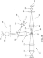
- FIG. 10 is a modal view showing the structure of the third measuring unit D3, which is an optical type measuring device.
- the third measuring unit D3 receives the measurement sample at a flow cell 301, a flow is formed in the flow cell 301, the blood cells contained in the flow passing within the flow cell 301 are irradiated by a semiconductor laser light, and the blood cells are measured.
- the third measuring unit D3 has a sheath flow system 300, beam spot system 310, forward scattered light receiving system 320, side scattered light receiving system 330, and side fluorescent light receiving system 340.
- the sheath flow system 300 forms a flow in which the blood cells contained in the measurement sample are aligned in a single row within the flow cell 301, thus improving the accuracy and reproducibility of the blood cell count.
- the beam spot system 310 is configured so that light emitted from the semiconductor laser 311 passes through a collimator lens 312 and condenser lens 313, and irradiates the flow cell 301.
- the beam spot system 310 is also provided with a beam stopper 314.
- the forward scattered light receiving system 320 is configured so that the forward scattered light is collected by a forward collector lens 321, and the light passing through a pinhole 322 is received by a forward scattered light receiver (photodiode) 323, and the signal output from the forward scattered light receiver 323 according to the amount of received light is amplified by an amplifier 324.
- the amplification factor of the amplifier 324 is set by the CPU 21.
- the side scattered light receiving system 330 is configured so that the side scattered light is collected by a side scattered light collector lens 331, and part of the light is reflected by a dichroic mirror 332, received by a side scattered light receiver (photodiode) 333, and the signal output from the side scattered light receiver 333 according to the amount of received light is amplified by an amplifier 334.
- the amplification factor of the amplifier 334 is set by the CPU 21.
- the scattered light is a phenomenon which occurs due to the change in the direction of travel of the light caused by the presence of an obstacle in the direction in which the light is traveling, that is, a particle, such as a blood cell.
- Information relating to the size and material quality of the particle can be obtained by detecting the scattered light.
- Particularly information relating to the size of the particle (blood cell) can be obtained from the forward scattered light.
- Information relating to the interior of the particle such as information concerning the material quality of the particle, can be obtained from the side scattered light.
- the side fluorescent light receiving system 340 is configured so that the light passing through the dichroic mirror 332 then passes through a spectral filter 341 and is received by a fluorescent light receiver (photomultiplier) 342, and the signal output from the fluorescent light receiver 342 according to the amount of received light is amplified by an amplifier 344.
- the amplification factor of the amplifier 344 is set by the CPU 21.
- the fluorescent material When a fluorescent material such as a stained blood cell is irradiated with light, the fluorescent material generates light that has a longer wavelength than the irradiating light.
- the fluorescent intensity becomes stronger under heavy staining, so that information relating to the degree of staining of the blood cell can be obtained by measuring the intensity of the fluorescent light. Other measurements such as the classification of the blood cell can be performed via the differences in the side fluorescent light intensity.
- the light receivers 323, 333, and 342 When light is received by the light receivers 323, 333, and 342, the light receivers 323, 333, and 342 output electrical pulse signals, and measurement data are generated based on the output electrical pulse signals.
- the measurement data are transmitted from the analyzer body 1 to the operation and display device 2, and undergo processing and analysis in the operation and display device 2.
- the operation and display device 2 counts the platelets by particle size analysis of the platelets based on the measurement data of the first measuring unit D1. More specifically, the platelet count is analyzed by a histogram in which the platelet volume (units: fL) is plotted on the horizontal axis, and the number of platelets is plotted on the vertical axis.
- the PLT measurement is performed by the first measuring unit D1 in the sample analyzer having the above configuration.
- the first measuring unit D1 When, for example, collapsed red blood cells contaminate the sample and the size of the particles is measured by the first measuring unit D1, the value of the red blood cells which approach the size of platelets cannot be ignored and it becomes difficult to accurately count the platelets.
- the PLT measurement is then performed by the third measuring unit D3.
- FIG. 11 is a flow chart showing the sequence of the processing by the CPU 21 of the operation and display device 2 of the first embodiment of the sample analyzer of the present invention.
- the CPU 21 of the operation and display device 2 obtains measurement data as a PLT measurement result from the controller 11 of the analyzer body 1 (step S1101).
- the CPU 21 generates a histogram based on the obtained measurement data (step S1102), and displays the histogram on the display device 25.
- the generated histogram plots the platelet volume on the horizontal axis and the PLT count on the vertical axis.
- the CPU 21 determines whether the measurement data are reliable (step S1103).
- the process of determining whether the PLT measurement data are reliable is not particularly limited.
- the measurement data are determined unreliable when the PLT count, that is, the number of platelets, is less than a predetermined value, or a platelet distribution anomaly occurs.
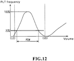
- FIG. 12 shows an illustration of the reliability determination based on a histogram.
- the histogram of FIG. 12 shots the PLT count (count values) plotted on the vertical axis and the platelet size plotted on the horizontal axis.
- LD is the platelet size when a predetermined small size is as a frequency standard
- UD is the platelet size when a predetermined large number is set as the frequency standard. That is, when the PLT count exceeds the LD frequency standard, the measurement data re determined to be unreliable due to the high possibility of impurities affecting the count.
- the PLT count exceeds the UD frequency standard the measurement data are determined to be unreliable due inadequate convergence when the count value is down, that is, the high possibility of impurities.
- the distribution width PDW is calculated for the 20% level when the height of the peak of the PLT count is 100%, And a distribution anomaly is determined to exist when PDW is greater than a predetermined standard width.
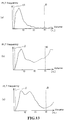
- FIG. 13 shows an illustration of a histogram based on PLT measurement data.
- FIG. 13(a) shows a pattern example of a measurement data histogram.
- the PLT count in LD and UD are adequately smaller than the frequency standard, And the distribution width PDW is also smaller than the standard width.
- FIG. 13(b) shows an example of a histogram when the UD platelet count value exceeds the frequency standard.
- the UD PLT frequency does not exceed the frequency standard, but the distribution width PDW does exceed the standard width, so a platelet distribution anomaly is determined.
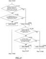
- FIG. 14 is a flow chart showing the sequence of the reliability determination process of the CPU 21 of the operation and display device 2 of the first embodiment of the sample analyzer of the present invention.
- the CPU 21 of the operation and display device 2 generates a histogram based on the obtained measurement data (step S1102), and determines whether a platelet distribution anomaly exists (step S1401).
- FIG. 15 shows an illustration of a scattergram representing the PLT re-measurement results of the first embodiment of the sample analyzer of the present invention.
- the forward scattered light intensity is plotted on the vertical axis
- the side fluorescent light intensity is plotted on the horizontal axis; measurements are performed by changing the stain (for example, Nile Blue) to increase the degree of staining of the platelets.
- the stain for example, Nile Blue
- the platelet count value is concentrated in region 1501, and there is no region in which the red blood cells and impurities intersect. Therefore, the blood can be analyzed with excellent precision by changing the detection method of the first embodiment, that is, the second detection condition according to the reliability of the first measurement data.
- the operation and display device 2 the platelets are respectively counted by analyzing the particle size of the platelets based on the measurement data of the first measuring unit D1 and the measurement data of the third measuring unit D3. More specifically, in the case of the measurement data of the first measuring unit D1, the platelet count is analyzed by creating a histogram and plotting the platelet volume on the horizontal axis and plotting the PLT frequency on the vertical axis. In the case of the measurement data of the third measuring unit D3, the platelet count is analyzed by creating a histogram and plotting the forward scattered light intensity on the horizontal axis and plotting the PLT frequency (platelet count) on the vertical axis.
Landscapes
- Health & Medical Sciences (AREA)
- Chemical & Material Sciences (AREA)
- Life Sciences & Earth Sciences (AREA)
- Immunology (AREA)
- Physics & Mathematics (AREA)
- Pathology (AREA)
- Analytical Chemistry (AREA)
- Biochemistry (AREA)
- General Health & Medical Sciences (AREA)
- General Physics & Mathematics (AREA)
- Engineering & Computer Science (AREA)
- Dispersion Chemistry (AREA)
- Biomedical Technology (AREA)
- Hematology (AREA)
- Molecular Biology (AREA)
- Urology & Nephrology (AREA)
- Quality & Reliability (AREA)
- Medicinal Chemistry (AREA)
- Ecology (AREA)
- Food Science & Technology (AREA)
- Cell Biology (AREA)
- Biophysics (AREA)
- Microbiology (AREA)
- Tropical Medicine & Parasitology (AREA)
- Biotechnology (AREA)
- Chemical Kinetics & Catalysis (AREA)
- Electrochemistry (AREA)
- Investigating Or Analysing Biological Materials (AREA)
- Automatic Analysis And Handling Materials Therefor (AREA)
Claims (18)
- Analyseur d'échantillon (1) comprenant :une section de préparation d'échantillon pour la préparation d'un premier et d'un deuxième échantillon de mesure comprenant un réactif et un échantillon ;un premier détecteur (D1) pour la détection d'un composant prédéterminé dans le premier échantillon de mesure préparé par la section de préparation d'échantillon ;un second détecteur (D2) pour la détection du composant prédéterminé dans le deuxième échantillon de mesure préparé par la section de préparation d'échantillon ; etun dispositif de commande (11) configuré pour réaliser des opérations, comprenant :(a) la commande du premier détecteur pour détecter le composant prédéterminé dans le premier échantillon de mesure préparé par la section de préparation d'échantillon ;(b) la détermination de la fiabilité du résultat détecté par le premier détecteur ;(c) la commande de la section de préparation d'échantillon pour préparer le deuxième échantillon de mesure à partir du même échantillon lorsque le résultat a été déterminé comme non fiable ; et(d) la commande du second détecteur pour détecter le composant prédéterminé dans le deuxième échantillon de mesure.
- Analyseur d'échantillon selon la revendication 1, dans lequel
le premier détecteur et le second détecteur sont configurés pour détecter le composant prédéterminé par des principes de détection mutuellement différents. - Analyseur d'échantillon selon la revendication 1 ou 2, dans lequel le premier détecteur comprend :une première cellule d'écoulement (113) à travers laquelle s'écoule le premier échantillon de mesure ; etun dispositif d'obtention d'informations électriques (115, 116, 117) pour l'obtention d'informations électriques lorsque le premier échantillon de mesure s'écoule à travers la première cellule d'écoulement ; etle second détecteur comprend :une seconde cellule d'écoulement (301) à travers laquelle s'écoule le deuxième échantillon de mesure ;une unité d'émission de lumière (311) pour l'irradiation d'une lumière sur le deuxième échantillon de mesure s'écoulant à travers la seconde cellule d'écoulement ; etune unité de réception de lumière (323, 333, 342) pour la réception d'une lumière provenant du deuxième échantillon de mesure irradié par la lumière de l'unité d'émission de lumière.
- Analyseur d'échantillon selon l'une quelconque des revendications 1 à 3, dans lequel
le second détecteur est configuré pour détecter en outre des globules blancs dans le sang. - Analyseur d'échantillon selon l'une quelconque des revendications 1 à 4, dans lequel
dans l'étape (c), le dispositif de commande commande la section de préparation d'échantillon pour préparer le deuxième échantillon de mesure à partir du même échantillon et un réactif différent du réactif utilisé dans le premier échantillon de mesure. - Analyseur d'échantillon selon l'une quelconque des revendications 1 à 5, dans lequel
l'échantillon est du sang ; et
le composant prédéterminé est une plaquette dans le sang. - Analyseur d'échantillon selon la revendication 6, dans lequel
dans l'étape (b), le dispositif de commande détermine que le résultat n'est pas fiable lorsque la numération plaquettaire est inférieure à une valeur prédéterminée ou lorsqu'une anomalie de distribution plaquettaire a lieu. - Analyseur d'échantillon (1) comprenant :une section de préparation d'échantillon pour la préparation d'un premier et d'un deuxième échantillon de mesure comprenant un réactif et un échantillon ;un premier détecteur (D1) pour la détection d'un composant prédéterminé dans le premier et le deuxième échantillon de mesure préparés par la section de préparation d'échantillon ; etun dispositif de commande (11) configuré pour réaliser des opérations, comprenant :(a) la commande du premier détecteur pour détecter le composant prédéterminé dans le premier échantillon de mesure préparé par la section de préparation d'échantillon en utilisant une première condition de détection ;(b) la détermination de la fiabilité du résultat détecté par le premier détecteur ;(c) la commande de la section de préparation d'échantillon pour préparer le deuxième échantillon de mesure à partir du même échantillon lorsque le résultat a été déterminé comme non fiable ; et(d) la commande du premier détecteur pour détecter le composant prédéterminé dans le deuxième échantillon de mesure en utilisant une seconde condition de détection qui est différente de la première condition de détection.
- Analyseur d'échantillon selon la revendication 8, dans lequel
la première condition de détection est une condition de détection d'une pluralité de types de composants, et la seconde condition de détection est une condition de détection de moins de types de composants que la première condition de détection. - Analyseur d'échantillon selon la revendication 8 ou 9, dans lequel
la première condition de détection est une condition de détection d'au moins deux types de composants, et la deuxième condition de détection est une condition de détection de seulement un type de composant. - Analyseur d'échantillon selon l'une quelconque des revendications 8 à 10, comprenant en outre :un second détecteur (D2) pour la détection du composant prédéterminé dans un troisième échantillon de mesure comprenant un échantillon et un réactif préparé par la section de préparation d'échantillon ; dans lequelle dispositif de commande est configuré pour réaliser d'autres opérations, comprenant:la détermination de la fiabilité du résultat du second détecteur, dans lequel le dispositif de commande détermine que le résultat n'est pas fiable lorsque le résultat détecté par le premier détecteur et le résultat détecté par le second détecteur sont tous deux non fiables.
- Analyseur d'échantillon selon la revendication 11, dans lequel
le dispositif de commande accepte un résultat déterminé comme fiable lorsque l'un ou l'autre résultat détecté par le premier détecteur et le résultat détecté par le second détecteur ont été déterminés comme fiables. - Analyseur d'échantillon selon la revendication 11 ou 12, dans lequel le second détecteur comprend :une première cellule d'écoulement (113) à travers laquelle s'écoule le troisième échantillon de mesure ; etun dispositif d'obtention d'informations électriques (115, 116, 117) pour l'obtention d'informations électriques lorsque le troisième échantillon de mesure s'écoule à travers la première cellule d'écoulement ; etle premier détecteur (D1) comprend :une seconde cellule d'écoulement (301) à travers laquelle s'écoule le premier et le deuxième échantillon de mesure ;une unité d'émission de lumière (311) pour l'irradiation d'une lumière sur le premier et le deuxième échantillon de mesure s'écoulant à travers la seconde cellule d'écoulement ; etune unité de réception de lumière (323, 333, 342) pour la réception d'une lumière provenant du premier et du deuxième échantillon de mesure irradiés par la lumière de l'unité d'émission de lumière ; etle dispositif de commande utilise le résultat détecté par le premier détecteur lorsque le résultat détecté par le premier détecteur a été déterminé comme fiable, quelle que soit la fiabilité du résultat détecté par le second détecteur.
- Analyseur d'échantillon selon l'une quelconque des revendications 8 à 13, dans lequel
le premier détecteur (D1) comprend :une seconde cellule d'écoulement (301) à travers laquelle s'écoule l'échantillon de mesure;une unité d'émission de lumière (311) pour l'irradiation d'une lumière sur le premier et le deuxième échantillon de mesure s'écoulant à travers la seconde cellule d'écoulement ; etune unité de réception de lumière (323, 333, 342) pour la réception d'une lumière provenant du premier et du deuxième échantillon de mesure irradiés par la lumière de l'unité d'émission de lumière ;les première et seconde conditions de détection concernent la sensibilité de détection de lumière de l'unité de réception de lumière, et la sensibilité de détection dans la seconde condition de détection est supérieure à la sensibilité de détection dans la première condition de détection. - Analyseur d'échantillon selon la revendication 14, dans lequel
l'unité de réception de lumière (323, 333, 342) comprend une partie de détection pour la détection d'une lumière et pour l'émission d'un signal correspondant à la quantité de lumière détectée, et un amplificateur (324, 334, 344) pour l'amplification du signal émis par la partie de détection ; et les première et seconde conditions de détection concernent le degré d'amplification par l'amplificateur. - Analyseur d'échantillon selon l'une quelconque des revendications 8 à 15, dans lequel
l'échantillon est du sang ; et
le composant prédéterminé est une plaquette dans le sang. - Analyseur d'échantillon selon la revendication 16, dans lequel
dans l'étape (b), le dispositif de commande détermine que le résultat n'est pas fiable lorsqu'une anomalie de distribution plaquettaire a lieu. - Analyseur d'échantillon selon la revendication 17, dans lequel
le dispositif de commande détermine qu'il y a une anomalie de distribution plaquettaire lorsque la région de distribution plaquettaire chevauche au moins partiellement la région de distribution d'un autre composant dans un nuage de points représentant les distributions de composants dans le sang.
Applications Claiming Priority (1)
| Application Number | Priority Date | Filing Date | Title |
|---|---|---|---|
| JP2008276637A JP5203889B2 (ja) | 2008-10-28 | 2008-10-28 | 検体分析装置及び検体分析方法 |
Publications (3)
| Publication Number | Publication Date |
|---|---|
| EP2182365A2 EP2182365A2 (fr) | 2010-05-05 |
| EP2182365A3 EP2182365A3 (fr) | 2017-06-28 |
| EP2182365B1 true EP2182365B1 (fr) | 2018-03-21 |
Family
ID=42040320
Family Applications (1)
| Application Number | Title | Priority Date | Filing Date |
|---|---|---|---|
| EP09013530.2A Active EP2182365B1 (fr) | 2008-10-28 | 2009-10-27 | Analyseur d'échantillon |
Country Status (4)
| Country | Link |
|---|---|
| US (3) | US20100106427A1 (fr) |
| EP (1) | EP2182365B1 (fr) |
| JP (1) | JP5203889B2 (fr) |
| CN (2) | CN101726609B (fr) |
Families Citing this family (30)
| Publication number | Priority date | Publication date | Assignee | Title |
|---|---|---|---|---|
| EP2646792B1 (fr) * | 2010-12-01 | 2019-07-10 | President and Fellows of Harvard College | Appareil et procédés permettant d'aliquoter des échantillons congelés |
| JP5865009B2 (ja) * | 2011-10-25 | 2016-02-17 | シスメックス株式会社 | 活性化好中球の検出方法 |
| CN103175766A (zh) * | 2011-12-23 | 2013-06-26 | 陶靖 | 一种用于微粒分析的自动化装置及方法 |
| CN103823073A (zh) * | 2013-06-03 | 2014-05-28 | 陶靖 | 用于样品处理和微粒分析的自动化装置及方法 |
| CN103439523A (zh) * | 2013-09-09 | 2013-12-11 | 陶靖 | 用于样品处理和微粒分析的装置和方法 |
| EP2857843A1 (fr) * | 2013-10-07 | 2015-04-08 | Eppendorf Ag | Système présentant au moins deux appareils de laboratoire pour le traitement commandé par un appareil d'une tâche relative à une pièce dans un processus de traitement contenant des traitements d'au moins un échantillon de laboratoire, appareil de laboratoire et procédé |
| DK2857841T3 (da) | 2013-10-07 | 2021-07-26 | Eppendorf Ag | Laboratorieapparat til apparatstyret behandling af mindst én laboratorieprøve, og en fremgangsmåde til konfigurering af laboratorieapparatet ved hjælp af konfigurationsstyringen |
| ES2904524T3 (es) | 2013-10-07 | 2022-04-05 | Eppendorf Ag | Instrumento de laboratorio, sistema y método para el procesamiento controlado por el instrumento de al menos una muestra de laboratorio mediante el uso de al menos un consumible |
| EP2857842B1 (fr) | 2013-10-07 | 2022-09-21 | Eppendorf SE | Commande d'accès pour un appareil de laboratoire, appareil de laboratoire avec commande d'accès et procédé de traitement d'échantillons de laboratoire commandé par un appareil |
| US9880085B2 (en) | 2014-03-21 | 2018-01-30 | Intellicyt Corporation | Flow cytometer system including flow cytometer, autosampler and system integration structure |
| US9835640B2 (en) | 2015-02-13 | 2017-12-05 | Abbott Laboratories | Automated storage modules for diagnostic analyzer liquids and related systems and methods |
| KR20170000281A (ko) | 2015-06-23 | 2017-01-02 | 허재영 | 스마트폰 |
| US10024780B2 (en) | 2015-12-18 | 2018-07-17 | Abbott Laboratories (Diagnostics Division) | Methods for detecting events in a flow cytometer |
| EP3258274B1 (fr) | 2016-06-17 | 2019-11-06 | Sysmex Corporation | Procédé de commande d'un analyseur de sang pour la mesure de plaquettes |
| CN110678734B (zh) * | 2017-06-29 | 2023-09-12 | 深圳迈瑞生物医疗电子股份有限公司 | 血液检测方法和设备 |
| US11303415B2 (en) | 2017-08-04 | 2022-04-12 | Sony Corporation | Wireless communication device, wireless communication method, and wireless communication system |
| CN107449718A (zh) * | 2017-08-14 | 2017-12-08 | 中生(苏州)医疗科技有限公司 | 一种带有卸料对接功能的全自动样本前处理系统 |
| WO2019047042A1 (fr) * | 2017-09-05 | 2019-03-14 | 深圳迈瑞生物医疗电子股份有限公司 | Procédé d'alarme d'échantillon à agrégation de plaquettes, analyseur de cellules sanguines et support d'informations |
| EP3546922B1 (fr) * | 2018-03-29 | 2021-06-30 | The Automation Partnership (Cambridge) Limited | Procédé et système informatisés pour l'analyse spectroscopique d'un matériau biologique |
| WO2019206312A1 (fr) | 2018-04-28 | 2019-10-31 | 深圳迈瑞生物医疗电子股份有限公司 | Procédé destiné à lancer une alarme relative à une anomalie dans un analyseur d'échantillon, système et support de stockage associés |
| JP7269692B2 (ja) * | 2018-09-26 | 2023-05-09 | シスメックス株式会社 | 検体測定システム及び検体測定方法 |
| CN111381059A (zh) * | 2018-12-29 | 2020-07-07 | 深圳市帝迈生物技术有限公司 | 样本分析仪 |
| JP7660123B2 (ja) | 2019-12-27 | 2025-04-10 | ベックマン コールター, インコーポレイテッド | サンプル調製器具 |
| EP3905260A1 (fr) * | 2020-04-28 | 2021-11-03 | Sysmex Corporation | Procédé, appareil et système de test sanguin |
| CN111707601A (zh) * | 2020-06-23 | 2020-09-25 | 合肥安为康医学检验有限公司 | 一种全血生化检测方法及装置 |
| CN114062696A (zh) * | 2020-08-04 | 2022-02-18 | 深圳迈瑞生物医疗电子股份有限公司 | 血样测量方法、血液测量装置、电子设备及计算机可读存储介质 |
| CN115219403A (zh) * | 2021-04-14 | 2022-10-21 | 深圳迈瑞生物医疗电子股份有限公司 | 一种血细胞的检测方法和检测装置 |
| CN116298335A (zh) * | 2021-12-21 | 2023-06-23 | 深圳市理邦精密仪器股份有限公司 | 样本分析仪及血细胞分析方法 |
| JP2025041387A (ja) | 2023-09-13 | 2025-03-26 | シスメックス株式会社 | 検体分析方法及び検体分析装置 |
| US12584902B2 (en) | 2023-12-10 | 2026-03-24 | Instrumentation Laboratory Company | Acoustic separation of a test sample |
Family Cites Families (13)
| Publication number | Priority date | Publication date | Assignee | Title |
|---|---|---|---|---|
| HU174711B (hu) * | 1976-04-20 | 1980-03-28 | Egyt Gyogyszervegyeszeti Gyar | Sposob i ustrojstvo analiza prob zhidkostej |
| JP2815435B2 (ja) * | 1989-12-22 | 1998-10-27 | 株式会社日立製作所 | 粒子解析装置及び血球カウンタ |
| US6667177B1 (en) * | 1997-11-11 | 2003-12-23 | Kowa Company, Ltd. | Method for counting leukocytes and apparatus for counting leukocytes |
| JP4101994B2 (ja) * | 1999-01-21 | 2008-06-18 | シスメックス株式会社 | 粒子分析装置および自動粒子分析方法 |
| WO2000058727A1 (fr) * | 1999-03-31 | 2000-10-05 | Bayer Corporation | Canal unique, procédé de détection par dilution unique |
| JP2001091519A (ja) * | 1999-09-24 | 2001-04-06 | Olympus Optical Co Ltd | 自動分析装置 |
| JP3823162B2 (ja) * | 2001-07-31 | 2006-09-20 | 株式会社エイアンドティー | 臨床検査分析装置、臨床検査分析方法および臨床検査分析プログラム |
| ATE443252T1 (de) * | 2001-11-30 | 2009-10-15 | Sysmex Corp | Teilchenanalysator |
| JP4744218B2 (ja) * | 2005-07-25 | 2011-08-10 | シスメックス株式会社 | 分析システム、検査情報処理装置、コンピュータプログラム、および分析装置 |
| JP4608405B2 (ja) * | 2005-10-03 | 2011-01-12 | シスメックス株式会社 | 生体試料分析方法及び生体試料分析装置 |
| JP4525624B2 (ja) * | 2006-03-23 | 2010-08-18 | 日立化成工業株式会社 | 自動分析装置 |
| JP4829677B2 (ja) * | 2006-05-18 | 2011-12-07 | シスメックス株式会社 | 試料分析装置 |
| JP4969293B2 (ja) * | 2007-03-30 | 2012-07-04 | シスメックス株式会社 | 検体分析装置 |
-
2008
- 2008-10-28 JP JP2008276637A patent/JP5203889B2/ja active Active
-
2009
- 2009-10-26 CN CN200910180077.0A patent/CN101726609B/zh active Active
- 2009-10-26 US US12/605,850 patent/US20100106427A1/en not_active Abandoned
- 2009-10-26 CN CN201410207700.8A patent/CN103941026B/zh active Active
- 2009-10-27 EP EP09013530.2A patent/EP2182365B1/fr active Active
-
2012
- 2012-11-08 US US13/672,172 patent/US8968653B2/en active Active
-
2015
- 2015-01-23 US US14/603,923 patent/US9816983B2/en active Active
Non-Patent Citations (1)
| Title |
|---|
| None * |
Also Published As
| Publication number | Publication date |
|---|---|
| CN101726609B (zh) | 2014-06-25 |
| US20130065317A1 (en) | 2013-03-14 |
| EP2182365A3 (fr) | 2017-06-28 |
| CN101726609A (zh) | 2010-06-09 |
| CN103941026B (zh) | 2016-01-20 |
| EP2182365A2 (fr) | 2010-05-05 |
| JP5203889B2 (ja) | 2013-06-05 |
| JP2010107216A (ja) | 2010-05-13 |
| US8968653B2 (en) | 2015-03-03 |
| CN103941026A (zh) | 2014-07-23 |
| US20150192573A1 (en) | 2015-07-09 |
| US9816983B2 (en) | 2017-11-14 |
| US20100106427A1 (en) | 2010-04-29 |
Similar Documents
| Publication | Publication Date | Title |
|---|---|---|
| EP2182365B1 (fr) | Analyseur d'échantillon | |
| EP3258274B1 (fr) | Procédé de commande d'un analyseur de sang pour la mesure de plaquettes | |
| US20190339258A1 (en) | Sample analyzer and computer program product | |
| EP2889620B1 (fr) | Analyseur de sang, procédé d'analyse de sang, agent hémolytique et agent colorant | |
| US8808624B2 (en) | Blood analyzer, blood analysis method and hemolytic agent | |
| US9453790B2 (en) | Blood analyzer, blood analyzing method, and computer program product | |
| EP2902769B1 (fr) | Analyseur de cellules sanguines | |
| US6525807B1 (en) | Particle analyzing apparatus | |
| US9746461B2 (en) | Urine sample analyzer and sample analyzing method | |
| US20080180653A1 (en) | Particle analyzer and particle analyzing method | |
| JP5478990B2 (ja) | 検体分析装置及びコンピュータプログラム | |
| JP2026502063A (ja) | マルチチャネル血液学フローシステム | |
| JP5432391B2 (ja) | 検体分析装置及び検体分析方法 | |
| JP5432390B2 (ja) | 検体分析装置及び検体分析方法 | |
| US20260110618A1 (en) | Sample measurement apparatus |
Legal Events
| Date | Code | Title | Description |
|---|---|---|---|
| PUAI | Public reference made under article 153(3) epc to a published international application that has entered the european phase |
Free format text: ORIGINAL CODE: 0009012 |
|
| AK | Designated contracting states |
Kind code of ref document: A2 Designated state(s): AT BE BG CH CY CZ DE DK EE ES FI FR GB GR HR HU IE IS IT LI LT LU LV MC MK MT NL NO PL PT RO SE SI SK SM TR |
|
| AX | Request for extension of the european patent |
Extension state: AL BA RS |
|
| PUAL | Search report despatched |
Free format text: ORIGINAL CODE: 0009013 |
|
| AK | Designated contracting states |
Kind code of ref document: A3 Designated state(s): AT BE BG CH CY CZ DE DK EE ES FI FR GB GR HR HU IE IS IT LI LT LU LV MC MK MT NL NO PL PT RO SE SI SK SM TR |
|
| AX | Request for extension of the european patent |
Extension state: AL BA RS |
|
| RIC1 | Information provided on ipc code assigned before grant |
Ipc: G01N 1/28 20060101ALI20170523BHEP Ipc: G01N 33/49 20060101ALI20170523BHEP Ipc: G01N 35/00 20060101AFI20170523BHEP Ipc: G01N 15/14 20060101ALI20170523BHEP Ipc: G01N 15/10 20060101ALI20170523BHEP Ipc: G01N 33/50 20060101ALI20170523BHEP |
|
| 17P | Request for examination filed |
Effective date: 20170623 |
|
| RBV | Designated contracting states (corrected) |
Designated state(s): AT BE BG CH CY CZ DE DK EE ES FI FR GB GR HR HU IE IS IT LI LT LU LV MC MK MT NL NO PL PT RO SE SI SK SM TR |
|
| REG | Reference to a national code |
Ref country code: DE Ref legal event code: R079 Ref document number: 602009051314 Country of ref document: DE Free format text: PREVIOUS MAIN CLASS: G01N0035000000 Ipc: G01N0015120000 |
|
| GRAP | Despatch of communication of intention to grant a patent |
Free format text: ORIGINAL CODE: EPIDOSNIGR1 |
|
| GRAJ | Information related to disapproval of communication of intention to grant by the applicant or resumption of examination proceedings by the epo deleted |
Free format text: ORIGINAL CODE: EPIDOSDIGR1 |
|
| RIC1 | Information provided on ipc code assigned before grant |
Ipc: G01N 35/00 20060101ALI20171018BHEP Ipc: G01N 15/14 20060101ALI20171018BHEP Ipc: G01N 33/49 20060101ALI20171018BHEP Ipc: G01N 15/12 20060101AFI20171018BHEP Ipc: G01N 15/06 20060101ALI20171018BHEP |
|
| GRAP | Despatch of communication of intention to grant a patent |
Free format text: ORIGINAL CODE: EPIDOSNIGR1 |
|
| INTG | Intention to grant announced |
Effective date: 20171110 |
|
| INTG | Intention to grant announced |
Effective date: 20171123 |
|
| GRAS | Grant fee paid |
Free format text: ORIGINAL CODE: EPIDOSNIGR3 |
|
| GRAA | (expected) grant |
Free format text: ORIGINAL CODE: 0009210 |
|
| AK | Designated contracting states |
Kind code of ref document: B1 Designated state(s): AT BE BG CH CY CZ DE DK EE ES FI FR GB GR HR HU IE IS IT LI LT LU LV MC MK MT NL NO PL PT RO SE SI SK SM TR |
|
| REG | Reference to a national code |
Ref country code: GB Ref legal event code: FG4D |
|
| REG | Reference to a national code |
Ref country code: CH Ref legal event code: EP |
|
| REG | Reference to a national code |
Ref country code: AT Ref legal event code: REF Ref document number: 981634 Country of ref document: AT Kind code of ref document: T Effective date: 20180415 |
|
| REG | Reference to a national code |
Ref country code: IE Ref legal event code: FG4D |
|
| REG | Reference to a national code |
Ref country code: DE Ref legal event code: R096 Ref document number: 602009051314 Country of ref document: DE |
|
| REG | Reference to a national code |
Ref country code: NL Ref legal event code: MP Effective date: 20180321 |
|
| PG25 | Lapsed in a contracting state [announced via postgrant information from national office to epo] |
Ref country code: HR Free format text: LAPSE BECAUSE OF FAILURE TO SUBMIT A TRANSLATION OF THE DESCRIPTION OR TO PAY THE FEE WITHIN THE PRESCRIBED TIME-LIMIT Effective date: 20180321 Ref country code: LT Free format text: LAPSE BECAUSE OF FAILURE TO SUBMIT A TRANSLATION OF THE DESCRIPTION OR TO PAY THE FEE WITHIN THE PRESCRIBED TIME-LIMIT Effective date: 20180321 Ref country code: FI Free format text: LAPSE BECAUSE OF FAILURE TO SUBMIT A TRANSLATION OF THE DESCRIPTION OR TO PAY THE FEE WITHIN THE PRESCRIBED TIME-LIMIT Effective date: 20180321 Ref country code: NO Free format text: LAPSE BECAUSE OF FAILURE TO SUBMIT A TRANSLATION OF THE DESCRIPTION OR TO PAY THE FEE WITHIN THE PRESCRIBED TIME-LIMIT Effective date: 20180621 Ref country code: CY Free format text: LAPSE BECAUSE OF FAILURE TO SUBMIT A TRANSLATION OF THE DESCRIPTION OR TO PAY THE FEE WITHIN THE PRESCRIBED TIME-LIMIT Effective date: 20180321 |
|
| REG | Reference to a national code |
Ref country code: LT Ref legal event code: MG4D |
|
| REG | Reference to a national code |
Ref country code: AT Ref legal event code: MK05 Ref document number: 981634 Country of ref document: AT Kind code of ref document: T Effective date: 20180321 |
|
| PG25 | Lapsed in a contracting state [announced via postgrant information from national office to epo] |
Ref country code: LV Free format text: LAPSE BECAUSE OF FAILURE TO SUBMIT A TRANSLATION OF THE DESCRIPTION OR TO PAY THE FEE WITHIN THE PRESCRIBED TIME-LIMIT Effective date: 20180321 Ref country code: GR Free format text: LAPSE BECAUSE OF FAILURE TO SUBMIT A TRANSLATION OF THE DESCRIPTION OR TO PAY THE FEE WITHIN THE PRESCRIBED TIME-LIMIT Effective date: 20180622 Ref country code: SE Free format text: LAPSE BECAUSE OF FAILURE TO SUBMIT A TRANSLATION OF THE DESCRIPTION OR TO PAY THE FEE WITHIN THE PRESCRIBED TIME-LIMIT Effective date: 20180321 Ref country code: BG Free format text: LAPSE BECAUSE OF FAILURE TO SUBMIT A TRANSLATION OF THE DESCRIPTION OR TO PAY THE FEE WITHIN THE PRESCRIBED TIME-LIMIT Effective date: 20180621 |
|
| REG | Reference to a national code |
Ref country code: FR Ref legal event code: PLFP Year of fee payment: 10 |
|
| PG25 | Lapsed in a contracting state [announced via postgrant information from national office to epo] |
Ref country code: RO Free format text: LAPSE BECAUSE OF FAILURE TO SUBMIT A TRANSLATION OF THE DESCRIPTION OR TO PAY THE FEE WITHIN THE PRESCRIBED TIME-LIMIT Effective date: 20180321 Ref country code: IT Free format text: LAPSE BECAUSE OF FAILURE TO SUBMIT A TRANSLATION OF THE DESCRIPTION OR TO PAY THE FEE WITHIN THE PRESCRIBED TIME-LIMIT Effective date: 20180321 Ref country code: NL Free format text: LAPSE BECAUSE OF FAILURE TO SUBMIT A TRANSLATION OF THE DESCRIPTION OR TO PAY THE FEE WITHIN THE PRESCRIBED TIME-LIMIT Effective date: 20180321 Ref country code: PL Free format text: LAPSE BECAUSE OF FAILURE TO SUBMIT A TRANSLATION OF THE DESCRIPTION OR TO PAY THE FEE WITHIN THE PRESCRIBED TIME-LIMIT Effective date: 20180321 Ref country code: ES Free format text: LAPSE BECAUSE OF FAILURE TO SUBMIT A TRANSLATION OF THE DESCRIPTION OR TO PAY THE FEE WITHIN THE PRESCRIBED TIME-LIMIT Effective date: 20180321 Ref country code: EE Free format text: LAPSE BECAUSE OF FAILURE TO SUBMIT A TRANSLATION OF THE DESCRIPTION OR TO PAY THE FEE WITHIN THE PRESCRIBED TIME-LIMIT Effective date: 20180321 |
|
| PG25 | Lapsed in a contracting state [announced via postgrant information from national office to epo] |
Ref country code: AT Free format text: LAPSE BECAUSE OF FAILURE TO SUBMIT A TRANSLATION OF THE DESCRIPTION OR TO PAY THE FEE WITHIN THE PRESCRIBED TIME-LIMIT Effective date: 20180321 Ref country code: SM Free format text: LAPSE BECAUSE OF FAILURE TO SUBMIT A TRANSLATION OF THE DESCRIPTION OR TO PAY THE FEE WITHIN THE PRESCRIBED TIME-LIMIT Effective date: 20180321 Ref country code: CZ Free format text: LAPSE BECAUSE OF FAILURE TO SUBMIT A TRANSLATION OF THE DESCRIPTION OR TO PAY THE FEE WITHIN THE PRESCRIBED TIME-LIMIT Effective date: 20180321 Ref country code: SK Free format text: LAPSE BECAUSE OF FAILURE TO SUBMIT A TRANSLATION OF THE DESCRIPTION OR TO PAY THE FEE WITHIN THE PRESCRIBED TIME-LIMIT Effective date: 20180321 |
|
| PG25 | Lapsed in a contracting state [announced via postgrant information from national office to epo] |
Ref country code: PT Free format text: LAPSE BECAUSE OF FAILURE TO SUBMIT A TRANSLATION OF THE DESCRIPTION OR TO PAY THE FEE WITHIN THE PRESCRIBED TIME-LIMIT Effective date: 20180723 |
|
| REG | Reference to a national code |
Ref country code: DE Ref legal event code: R097 Ref document number: 602009051314 Country of ref document: DE |
|
| PLBE | No opposition filed within time limit |
Free format text: ORIGINAL CODE: 0009261 |
|
| STAA | Information on the status of an ep patent application or granted ep patent |
Free format text: STATUS: NO OPPOSITION FILED WITHIN TIME LIMIT |
|
| PG25 | Lapsed in a contracting state [announced via postgrant information from national office to epo] |
Ref country code: DK Free format text: LAPSE BECAUSE OF FAILURE TO SUBMIT A TRANSLATION OF THE DESCRIPTION OR TO PAY THE FEE WITHIN THE PRESCRIBED TIME-LIMIT Effective date: 20180321 |
|
| 26N | No opposition filed |
Effective date: 20190102 |
|
| PG25 | Lapsed in a contracting state [announced via postgrant information from national office to epo] |
Ref country code: SI Free format text: LAPSE BECAUSE OF FAILURE TO SUBMIT A TRANSLATION OF THE DESCRIPTION OR TO PAY THE FEE WITHIN THE PRESCRIBED TIME-LIMIT Effective date: 20180321 |
|
| REG | Reference to a national code |
Ref country code: CH Ref legal event code: PL |
|
| REG | Reference to a national code |
Ref country code: BE Ref legal event code: MM Effective date: 20181031 |
|
| PG25 | Lapsed in a contracting state [announced via postgrant information from national office to epo] |
Ref country code: MC Free format text: LAPSE BECAUSE OF FAILURE TO SUBMIT A TRANSLATION OF THE DESCRIPTION OR TO PAY THE FEE WITHIN THE PRESCRIBED TIME-LIMIT Effective date: 20180321 Ref country code: LU Free format text: LAPSE BECAUSE OF NON-PAYMENT OF DUE FEES Effective date: 20181027 |
|
| REG | Reference to a national code |
Ref country code: IE Ref legal event code: MM4A |
|
| PG25 | Lapsed in a contracting state [announced via postgrant information from national office to epo] |
Ref country code: BE Free format text: LAPSE BECAUSE OF NON-PAYMENT OF DUE FEES Effective date: 20181031 Ref country code: CH Free format text: LAPSE BECAUSE OF NON-PAYMENT OF DUE FEES Effective date: 20181031 Ref country code: LI Free format text: LAPSE BECAUSE OF NON-PAYMENT OF DUE FEES Effective date: 20181031 |
|
| PG25 | Lapsed in a contracting state [announced via postgrant information from national office to epo] |
Ref country code: IE Free format text: LAPSE BECAUSE OF NON-PAYMENT OF DUE FEES Effective date: 20181027 |
|
| PG25 | Lapsed in a contracting state [announced via postgrant information from national office to epo] |
Ref country code: MT Free format text: LAPSE BECAUSE OF NON-PAYMENT OF DUE FEES Effective date: 20181027 |
|
| PG25 | Lapsed in a contracting state [announced via postgrant information from national office to epo] |
Ref country code: TR Free format text: LAPSE BECAUSE OF FAILURE TO SUBMIT A TRANSLATION OF THE DESCRIPTION OR TO PAY THE FEE WITHIN THE PRESCRIBED TIME-LIMIT Effective date: 20180321 |
|
| PG25 | Lapsed in a contracting state [announced via postgrant information from national office to epo] |
Ref country code: MK Free format text: LAPSE BECAUSE OF NON-PAYMENT OF DUE FEES Effective date: 20180321 Ref country code: HU Free format text: LAPSE BECAUSE OF FAILURE TO SUBMIT A TRANSLATION OF THE DESCRIPTION OR TO PAY THE FEE WITHIN THE PRESCRIBED TIME-LIMIT; INVALID AB INITIO Effective date: 20091027 |
|
| PG25 | Lapsed in a contracting state [announced via postgrant information from national office to epo] |
Ref country code: IS Free format text: LAPSE BECAUSE OF FAILURE TO SUBMIT A TRANSLATION OF THE DESCRIPTION OR TO PAY THE FEE WITHIN THE PRESCRIBED TIME-LIMIT Effective date: 20180721 |
|
| PGFP | Annual fee paid to national office [announced via postgrant information from national office to epo] |
Ref country code: GB Payment date: 20250904 Year of fee payment: 17 |
|
| PGFP | Annual fee paid to national office [announced via postgrant information from national office to epo] |
Ref country code: FR Payment date: 20250908 Year of fee payment: 17 |
|
| PGFP | Annual fee paid to national office [announced via postgrant information from national office to epo] |
Ref country code: DE Payment date: 20250902 Year of fee payment: 17 |